EP0303438A2 - Production of synthesis gas from hydrocarbonaceous feedstock - Google Patents
Production of synthesis gas from hydrocarbonaceous feedstock Download PDFInfo
- Publication number
- EP0303438A2 EP0303438A2 EP88307342A EP88307342A EP0303438A2 EP 0303438 A2 EP0303438 A2 EP 0303438A2 EP 88307342 A EP88307342 A EP 88307342A EP 88307342 A EP88307342 A EP 88307342A EP 0303438 A2 EP0303438 A2 EP 0303438A2
- Authority
- EP
- European Patent Office
- Prior art keywords
- steam
- partial oxidation
- oxygen
- temperature
- catalyst
- Prior art date
- Legal status (The legal status is an assumption and is not a legal conclusion. Google has not performed a legal analysis and makes no representation as to the accuracy of the status listed.)
- Withdrawn
Links
- 230000015572 biosynthetic process Effects 0.000 title claims abstract description 25
- 238000003786 synthesis reaction Methods 0.000 title claims abstract description 25
- 238000004519 manufacturing process Methods 0.000 title description 12
- 239000007789 gas Substances 0.000 claims abstract description 68
- 238000007254 oxidation reaction Methods 0.000 claims abstract description 64
- 239000003054 catalyst Substances 0.000 claims abstract description 63
- 238000000034 method Methods 0.000 claims abstract description 60
- 230000003197 catalytic effect Effects 0.000 claims abstract description 56
- 230000003647 oxidation Effects 0.000 claims abstract description 55
- 229910052799 carbon Inorganic materials 0.000 claims abstract description 35
- QVGXLLKOCUKJST-UHFFFAOYSA-N atomic oxygen Chemical compound [O] QVGXLLKOCUKJST-UHFFFAOYSA-N 0.000 claims abstract description 30
- 239000001301 oxygen Substances 0.000 claims abstract description 30
- 229910052760 oxygen Inorganic materials 0.000 claims abstract description 30
- 239000000203 mixture Substances 0.000 claims abstract description 25
- VNWKTOKETHGBQD-UHFFFAOYSA-N methane Chemical compound C VNWKTOKETHGBQD-UHFFFAOYSA-N 0.000 claims description 42
- 238000006243 chemical reaction Methods 0.000 claims description 32
- 239000000463 material Substances 0.000 claims description 21
- 229910052739 hydrogen Inorganic materials 0.000 claims description 14
- 239000001257 hydrogen Substances 0.000 claims description 14
- UGFAIRIUMAVXCW-UHFFFAOYSA-N Carbon monoxide Chemical class [O+]#[C-] UGFAIRIUMAVXCW-UHFFFAOYSA-N 0.000 claims description 12
- PXHVJJICTQNCMI-UHFFFAOYSA-N Nickel Chemical compound [Ni] PXHVJJICTQNCMI-UHFFFAOYSA-N 0.000 claims description 12
- BASFCYQUMIYNBI-UHFFFAOYSA-N platinum Chemical compound [Pt] BASFCYQUMIYNBI-UHFFFAOYSA-N 0.000 claims description 12
- UFHFLCQGNIYNRP-UHFFFAOYSA-N Hydrogen Chemical compound [H][H] UFHFLCQGNIYNRP-UHFFFAOYSA-N 0.000 claims description 11
- 229930195733 hydrocarbon Natural products 0.000 claims description 11
- 150000002430 hydrocarbons Chemical class 0.000 claims description 11
- KDLHZDBZIXYQEI-UHFFFAOYSA-N Palladium Chemical compound [Pd] KDLHZDBZIXYQEI-UHFFFAOYSA-N 0.000 claims description 10
- 239000003345 natural gas Substances 0.000 claims description 10
- PNEYBMLMFCGWSK-UHFFFAOYSA-N aluminium oxide Inorganic materials [O-2].[O-2].[O-2].[Al+3].[Al+3] PNEYBMLMFCGWSK-UHFFFAOYSA-N 0.000 claims description 9
- 239000008246 gaseous mixture Substances 0.000 claims description 9
- 230000001590 oxidative effect Effects 0.000 claims description 8
- MCMNRKCIXSYSNV-UHFFFAOYSA-N Zirconium dioxide Chemical compound O=[Zr]=O MCMNRKCIXSYSNV-UHFFFAOYSA-N 0.000 claims description 6
- 229910052878 cordierite Inorganic materials 0.000 claims description 6
- JSKIRARMQDRGJZ-UHFFFAOYSA-N dimagnesium dioxido-bis[(1-oxido-3-oxo-2,4,6,8,9-pentaoxa-1,3-disila-5,7-dialuminabicyclo[3.3.1]nonan-7-yl)oxy]silane Chemical compound [Mg++].[Mg++].[O-][Si]([O-])(O[Al]1O[Al]2O[Si](=O)O[Si]([O-])(O1)O2)O[Al]1O[Al]2O[Si](=O)O[Si]([O-])(O1)O2 JSKIRARMQDRGJZ-UHFFFAOYSA-N 0.000 claims description 6
- -1 irridium Chemical compound 0.000 claims description 6
- 229910052759 nickel Inorganic materials 0.000 claims description 6
- 229910052697 platinum Inorganic materials 0.000 claims description 6
- 229910052763 palladium Inorganic materials 0.000 claims description 5
- 229910052703 rhodium Inorganic materials 0.000 claims description 5
- 239000010948 rhodium Substances 0.000 claims description 5
- MHOVAHRLVXNVSD-UHFFFAOYSA-N rhodium atom Chemical compound [Rh] MHOVAHRLVXNVSD-UHFFFAOYSA-N 0.000 claims description 5
- 239000004215 Carbon black (E152) Substances 0.000 claims description 4
- VYZAMTAEIAYCRO-UHFFFAOYSA-N Chromium Chemical compound [Cr] VYZAMTAEIAYCRO-UHFFFAOYSA-N 0.000 claims description 4
- KJTLSVCANCCWHF-UHFFFAOYSA-N Ruthenium Chemical compound [Ru] KJTLSVCANCCWHF-UHFFFAOYSA-N 0.000 claims description 4
- 229910052804 chromium Inorganic materials 0.000 claims description 4
- 239000011651 chromium Substances 0.000 claims description 4
- KZHJGOXRZJKJNY-UHFFFAOYSA-N dioxosilane;oxo(oxoalumanyloxy)alumane Chemical compound O=[Si]=O.O=[Si]=O.O=[Al]O[Al]=O.O=[Al]O[Al]=O.O=[Al]O[Al]=O KZHJGOXRZJKJNY-UHFFFAOYSA-N 0.000 claims description 4
- 229910052746 lanthanum Inorganic materials 0.000 claims description 4
- FZLIPJUXYLNCLC-UHFFFAOYSA-N lanthanum atom Chemical compound [La] FZLIPJUXYLNCLC-UHFFFAOYSA-N 0.000 claims description 4
- 229910052863 mullite Inorganic materials 0.000 claims description 4
- 229910052762 osmium Inorganic materials 0.000 claims description 4
- SYQBFIAQOQZEGI-UHFFFAOYSA-N osmium atom Chemical compound [Os] SYQBFIAQOQZEGI-UHFFFAOYSA-N 0.000 claims description 4
- 229910052707 ruthenium Inorganic materials 0.000 claims description 4
- 229910052596 spinel Inorganic materials 0.000 claims description 4
- 239000011029 spinel Substances 0.000 claims description 4
- 238000000629 steam reforming Methods 0.000 claims description 4
- 239000000758 substrate Substances 0.000 claims description 4
- 229910052684 Cerium Inorganic materials 0.000 claims description 3
- 229910002090 carbon oxide Inorganic materials 0.000 claims description 3
- GWXLDORMOJMVQZ-UHFFFAOYSA-N cerium Chemical compound [Ce] GWXLDORMOJMVQZ-UHFFFAOYSA-N 0.000 claims description 3
- 229910017052 cobalt Inorganic materials 0.000 claims description 3
- 239000010941 cobalt Substances 0.000 claims description 3
- GUTLYIVDDKVIGB-UHFFFAOYSA-N cobalt atom Chemical compound [Co] GUTLYIVDDKVIGB-UHFFFAOYSA-N 0.000 claims description 3
- 150000002431 hydrogen Chemical class 0.000 claims description 3
- 229910000505 Al2TiO5 Inorganic materials 0.000 claims description 2
- 238000012886 linear function Methods 0.000 claims description 2
- AABBHSMFGKYLKE-SNAWJCMRSA-N propan-2-yl (e)-but-2-enoate Chemical compound C\C=C\C(=O)OC(C)C AABBHSMFGKYLKE-SNAWJCMRSA-N 0.000 claims description 2
- 239000011541 reaction mixture Substances 0.000 claims 1
- 239000000376 reactant Substances 0.000 description 16
- 229910052751 metal Inorganic materials 0.000 description 14
- 239000002184 metal Substances 0.000 description 14
- 239000000047 product Substances 0.000 description 14
- CURLTUGMZLYLDI-UHFFFAOYSA-N Carbon dioxide Chemical compound O=C=O CURLTUGMZLYLDI-UHFFFAOYSA-N 0.000 description 10
- 229910002091 carbon monoxide Inorganic materials 0.000 description 9
- 238000002156 mixing Methods 0.000 description 7
- OKKJLVBELUTLKV-UHFFFAOYSA-N Methanol Chemical compound OC OKKJLVBELUTLKV-UHFFFAOYSA-N 0.000 description 6
- VYPSYNLAJGMNEJ-UHFFFAOYSA-N Silicium dioxide Chemical compound O=[Si]=O VYPSYNLAJGMNEJ-UHFFFAOYSA-N 0.000 description 6
- 150000002739 metals Chemical class 0.000 description 6
- OKTJSMMVPCPJKN-UHFFFAOYSA-N Carbon Chemical compound [C] OKTJSMMVPCPJKN-UHFFFAOYSA-N 0.000 description 5
- 229910002092 carbon dioxide Inorganic materials 0.000 description 5
- 239000001569 carbon dioxide Substances 0.000 description 5
- 239000000446 fuel Substances 0.000 description 5
- 238000009413 insulation Methods 0.000 description 5
- QGZKDVFQNNGYKY-UHFFFAOYSA-N Ammonia Chemical compound N QGZKDVFQNNGYKY-UHFFFAOYSA-N 0.000 description 4
- ATUOYWHBWRKTHZ-UHFFFAOYSA-N Propane Chemical compound CCC ATUOYWHBWRKTHZ-UHFFFAOYSA-N 0.000 description 4
- 229910044991 metal oxide Inorganic materials 0.000 description 4
- 150000004706 metal oxides Chemical class 0.000 description 4
- 239000007800 oxidant agent Substances 0.000 description 4
- 238000012856 packing Methods 0.000 description 4
- 229910045601 alloy Inorganic materials 0.000 description 3
- 239000000956 alloy Substances 0.000 description 3
- UQMRAFJOBWOFNS-UHFFFAOYSA-N butyl 2-(2,4-dichlorophenoxy)acetate Chemical compound CCCCOC(=O)COC1=CC=C(Cl)C=C1Cl UQMRAFJOBWOFNS-UHFFFAOYSA-N 0.000 description 3
- 239000000919 ceramic Substances 0.000 description 3
- 229910052681 coesite Inorganic materials 0.000 description 3
- 229910052906 cristobalite Inorganic materials 0.000 description 3
- 239000007788 liquid Substances 0.000 description 3
- 238000006057 reforming reaction Methods 0.000 description 3
- 239000000377 silicon dioxide Substances 0.000 description 3
- 235000012239 silicon dioxide Nutrition 0.000 description 3
- 229910052682 stishovite Inorganic materials 0.000 description 3
- 238000012546 transfer Methods 0.000 description 3
- 229910052905 tridymite Inorganic materials 0.000 description 3
- OTMSDBZUPAUEDD-UHFFFAOYSA-N Ethane Chemical compound CC OTMSDBZUPAUEDD-UHFFFAOYSA-N 0.000 description 2
- GWEVSGVZZGPLCZ-UHFFFAOYSA-N Titan oxide Chemical compound O=[Ti]=O GWEVSGVZZGPLCZ-UHFFFAOYSA-N 0.000 description 2
- 229910021529 ammonia Inorganic materials 0.000 description 2
- 238000009835 boiling Methods 0.000 description 2
- 239000001273 butane Substances 0.000 description 2
- 239000007795 chemical reaction product Substances 0.000 description 2
- 238000010276 construction Methods 0.000 description 2
- 230000000694 effects Effects 0.000 description 2
- IJDNQMDRQITEOD-UHFFFAOYSA-N n-butane Chemical compound CCCC IJDNQMDRQITEOD-UHFFFAOYSA-N 0.000 description 2
- OFBQJSOFQDEBGM-UHFFFAOYSA-N n-pentane Natural products CCCCC OFBQJSOFQDEBGM-UHFFFAOYSA-N 0.000 description 2
- 230000036284 oxygen consumption Effects 0.000 description 2
- 238000012545 processing Methods 0.000 description 2
- 239000001294 propane Substances 0.000 description 2
- 229910001220 stainless steel Inorganic materials 0.000 description 2
- XLYOFNOQVPJJNP-UHFFFAOYSA-N water Substances O XLYOFNOQVPJJNP-UHFFFAOYSA-N 0.000 description 2
- 229910001868 water Inorganic materials 0.000 description 2
- 229910000975 Carbon steel Inorganic materials 0.000 description 1
- ZOKXTWBITQBERF-UHFFFAOYSA-N Molybdenum Chemical compound [Mo] ZOKXTWBITQBERF-UHFFFAOYSA-N 0.000 description 1
- 229910000990 Ni alloy Inorganic materials 0.000 description 1
- 238000010521 absorption reaction Methods 0.000 description 1
- 239000011449 brick Substances 0.000 description 1
- 229910052792 caesium Inorganic materials 0.000 description 1
- TVFDJXOCXUVLDH-UHFFFAOYSA-N caesium atom Chemical compound [Cs] TVFDJXOCXUVLDH-UHFFFAOYSA-N 0.000 description 1
- 239000011203 carbon fibre reinforced carbon Substances 0.000 description 1
- RVYIIQVVKDJVBA-UHFFFAOYSA-N carbon monoxide;methane Chemical class C.O=[C] RVYIIQVVKDJVBA-UHFFFAOYSA-N 0.000 description 1
- 239000010962 carbon steel Substances 0.000 description 1
- 238000007084 catalytic combustion reaction Methods 0.000 description 1
- 238000006555 catalytic reaction Methods 0.000 description 1
- 238000001833 catalytic reforming Methods 0.000 description 1
- 238000001193 catalytic steam reforming Methods 0.000 description 1
- IUWCPXJTIPQGTE-UHFFFAOYSA-N chromium cobalt Chemical compound [Cr].[Co].[Co].[Co] IUWCPXJTIPQGTE-UHFFFAOYSA-N 0.000 description 1
- 239000011248 coating agent Substances 0.000 description 1
- 238000000576 coating method Methods 0.000 description 1
- 239000000470 constituent Substances 0.000 description 1
- 238000005260 corrosion Methods 0.000 description 1
- 230000007797 corrosion Effects 0.000 description 1
- 230000001419 dependent effect Effects 0.000 description 1
- 238000009826 distribution Methods 0.000 description 1
- 239000000835 fiber Substances 0.000 description 1
- 238000010304 firing Methods 0.000 description 1
- 239000012535 impurity Substances 0.000 description 1
- 229910052742 iron Inorganic materials 0.000 description 1
- 229910052750 molybdenum Inorganic materials 0.000 description 1
- 239000011733 molybdenum Substances 0.000 description 1
- 229910000510 noble metal Inorganic materials 0.000 description 1
- 238000013021 overheating Methods 0.000 description 1
- 239000002245 particle Substances 0.000 description 1
- 230000000737 periodic effect Effects 0.000 description 1
- 239000003208 petroleum Substances 0.000 description 1
- 238000002360 preparation method Methods 0.000 description 1
- 238000011084 recovery Methods 0.000 description 1
- 239000011819 refractory material Substances 0.000 description 1
- 238000000926 separation method Methods 0.000 description 1
- 238000005245 sintering Methods 0.000 description 1
- 239000002002 slurry Substances 0.000 description 1
- 239000010935 stainless steel Substances 0.000 description 1
- 239000000126 substance Substances 0.000 description 1
- 239000002699 waste material Substances 0.000 description 1
Images


Classifications
-
- C—CHEMISTRY; METALLURGY
- C01—INORGANIC CHEMISTRY
- C01B—NON-METALLIC ELEMENTS; COMPOUNDS THEREOF; METALLOIDS OR COMPOUNDS THEREOF NOT COVERED BY SUBCLASS C01C
- C01B3/00—Hydrogen; Gaseous mixtures containing hydrogen; Separation of hydrogen from mixtures containing it; Purification of hydrogen
- C01B3/02—Production of hydrogen or of gaseous mixtures containing a substantial proportion of hydrogen
- C01B3/22—Production of hydrogen or of gaseous mixtures containing a substantial proportion of hydrogen by decomposition of gaseous or liquid organic compounds
- C01B3/24—Production of hydrogen or of gaseous mixtures containing a substantial proportion of hydrogen by decomposition of gaseous or liquid organic compounds of hydrocarbons
-
- B—PERFORMING OPERATIONS; TRANSPORTING
- B01—PHYSICAL OR CHEMICAL PROCESSES OR APPARATUS IN GENERAL
- B01J—CHEMICAL OR PHYSICAL PROCESSES, e.g. CATALYSIS OR COLLOID CHEMISTRY; THEIR RELEVANT APPARATUS
- B01J8/00—Chemical or physical processes in general, conducted in the presence of fluids and solid particles; Apparatus for such processes
- B01J8/02—Chemical or physical processes in general, conducted in the presence of fluids and solid particles; Apparatus for such processes with stationary particles, e.g. in fixed beds
- B01J8/0278—Feeding reactive fluids
-
- B—PERFORMING OPERATIONS; TRANSPORTING
- B01—PHYSICAL OR CHEMICAL PROCESSES OR APPARATUS IN GENERAL
- B01F—MIXING, e.g. DISSOLVING, EMULSIFYING OR DISPERSING
- B01F25/00—Flow mixers; Mixers for falling materials, e.g. solid particles
- B01F25/30—Injector mixers
- B01F25/31—Injector mixers in conduits or tubes through which the main component flows
- B01F25/314—Injector mixers in conduits or tubes through which the main component flows wherein additional components are introduced at the circumference of the conduit
- B01F25/3142—Injector mixers in conduits or tubes through which the main component flows wherein additional components are introduced at the circumference of the conduit the conduit having a plurality of openings in the axial direction or in the circumferential direction
- B01F25/31422—Injector mixers in conduits or tubes through which the main component flows wherein additional components are introduced at the circumference of the conduit the conduit having a plurality of openings in the axial direction or in the circumferential direction with a plurality of perforations in the axial direction only
-
- B—PERFORMING OPERATIONS; TRANSPORTING
- B01—PHYSICAL OR CHEMICAL PROCESSES OR APPARATUS IN GENERAL
- B01F—MIXING, e.g. DISSOLVING, EMULSIFYING OR DISPERSING
- B01F25/00—Flow mixers; Mixers for falling materials, e.g. solid particles
- B01F25/30—Injector mixers
- B01F25/31—Injector mixers in conduits or tubes through which the main component flows
- B01F25/314—Injector mixers in conduits or tubes through which the main component flows wherein additional components are introduced at the circumference of the conduit
- B01F25/3143—Injector mixers in conduits or tubes through which the main component flows wherein additional components are introduced at the circumference of the conduit characterised by the specific design of the injector
- B01F25/31434—Injector mixers in conduits or tubes through which the main component flows wherein additional components are introduced at the circumference of the conduit characterised by the specific design of the injector being a bundle of similar tubes, each of them having feedings on the circumferential wall, e.g. as mixer for a reactor
-
- B01J35/56—
-
- C—CHEMISTRY; METALLURGY
- C01—INORGANIC CHEMISTRY
- C01B—NON-METALLIC ELEMENTS; COMPOUNDS THEREOF; METALLOIDS OR COMPOUNDS THEREOF NOT COVERED BY SUBCLASS C01C
- C01B3/00—Hydrogen; Gaseous mixtures containing hydrogen; Separation of hydrogen from mixtures containing it; Purification of hydrogen
- C01B3/02—Production of hydrogen or of gaseous mixtures containing a substantial proportion of hydrogen
- C01B3/32—Production of hydrogen or of gaseous mixtures containing a substantial proportion of hydrogen by reaction of gaseous or liquid organic compounds with gasifying agents, e.g. water, carbon dioxide, air
- C01B3/34—Production of hydrogen or of gaseous mixtures containing a substantial proportion of hydrogen by reaction of gaseous or liquid organic compounds with gasifying agents, e.g. water, carbon dioxide, air by reaction of hydrocarbons with gasifying agents
- C01B3/38—Production of hydrogen or of gaseous mixtures containing a substantial proportion of hydrogen by reaction of gaseous or liquid organic compounds with gasifying agents, e.g. water, carbon dioxide, air by reaction of hydrocarbons with gasifying agents using catalysts
- C01B3/386—Catalytic partial combustion
-
- C—CHEMISTRY; METALLURGY
- C01—INORGANIC CHEMISTRY
- C01B—NON-METALLIC ELEMENTS; COMPOUNDS THEREOF; METALLOIDS OR COMPOUNDS THEREOF NOT COVERED BY SUBCLASS C01C
- C01B3/00—Hydrogen; Gaseous mixtures containing hydrogen; Separation of hydrogen from mixtures containing it; Purification of hydrogen
- C01B3/02—Production of hydrogen or of gaseous mixtures containing a substantial proportion of hydrogen
- C01B3/32—Production of hydrogen or of gaseous mixtures containing a substantial proportion of hydrogen by reaction of gaseous or liquid organic compounds with gasifying agents, e.g. water, carbon dioxide, air
- C01B3/34—Production of hydrogen or of gaseous mixtures containing a substantial proportion of hydrogen by reaction of gaseous or liquid organic compounds with gasifying agents, e.g. water, carbon dioxide, air by reaction of hydrocarbons with gasifying agents
- C01B3/38—Production of hydrogen or of gaseous mixtures containing a substantial proportion of hydrogen by reaction of gaseous or liquid organic compounds with gasifying agents, e.g. water, carbon dioxide, air by reaction of hydrocarbons with gasifying agents using catalysts
- C01B3/40—Production of hydrogen or of gaseous mixtures containing a substantial proportion of hydrogen by reaction of gaseous or liquid organic compounds with gasifying agents, e.g. water, carbon dioxide, air by reaction of hydrocarbons with gasifying agents using catalysts characterised by the catalyst
-
- C—CHEMISTRY; METALLURGY
- C01—INORGANIC CHEMISTRY
- C01B—NON-METALLIC ELEMENTS; COMPOUNDS THEREOF; METALLOIDS OR COMPOUNDS THEREOF NOT COVERED BY SUBCLASS C01C
- C01B2203/00—Integrated processes for the production of hydrogen or synthesis gas
- C01B2203/02—Processes for making hydrogen or synthesis gas
- C01B2203/025—Processes for making hydrogen or synthesis gas containing a partial oxidation step
- C01B2203/0261—Processes for making hydrogen or synthesis gas containing a partial oxidation step containing a catalytic partial oxidation step [CPO]
-
- C—CHEMISTRY; METALLURGY
- C01—INORGANIC CHEMISTRY
- C01B—NON-METALLIC ELEMENTS; COMPOUNDS THEREOF; METALLOIDS OR COMPOUNDS THEREOF NOT COVERED BY SUBCLASS C01C
- C01B2203/00—Integrated processes for the production of hydrogen or synthesis gas
- C01B2203/10—Catalysts for performing the hydrogen forming reactions
- C01B2203/1005—Arrangement or shape of catalyst
- C01B2203/1011—Packed bed of catalytic structures, e.g. particles, packing elements
-
- C—CHEMISTRY; METALLURGY
- C01—INORGANIC CHEMISTRY
- C01B—NON-METALLIC ELEMENTS; COMPOUNDS THEREOF; METALLOIDS OR COMPOUNDS THEREOF NOT COVERED BY SUBCLASS C01C
- C01B2203/00—Integrated processes for the production of hydrogen or synthesis gas
- C01B2203/10—Catalysts for performing the hydrogen forming reactions
- C01B2203/1005—Arrangement or shape of catalyst
- C01B2203/1023—Catalysts in the form of a monolith or honeycomb
-
- C—CHEMISTRY; METALLURGY
- C01—INORGANIC CHEMISTRY
- C01B—NON-METALLIC ELEMENTS; COMPOUNDS THEREOF; METALLOIDS OR COMPOUNDS THEREOF NOT COVERED BY SUBCLASS C01C
- C01B2203/00—Integrated processes for the production of hydrogen or synthesis gas
- C01B2203/10—Catalysts for performing the hydrogen forming reactions
- C01B2203/1041—Composition of the catalyst
- C01B2203/1047—Group VIII metal catalysts
- C01B2203/1052—Nickel or cobalt catalysts
-
- C—CHEMISTRY; METALLURGY
- C01—INORGANIC CHEMISTRY
- C01B—NON-METALLIC ELEMENTS; COMPOUNDS THEREOF; METALLOIDS OR COMPOUNDS THEREOF NOT COVERED BY SUBCLASS C01C
- C01B2203/00—Integrated processes for the production of hydrogen or synthesis gas
- C01B2203/10—Catalysts for performing the hydrogen forming reactions
- C01B2203/1041—Composition of the catalyst
- C01B2203/1047—Group VIII metal catalysts
- C01B2203/1064—Platinum group metal catalysts
- C01B2203/107—Platinum catalysts
-
- C—CHEMISTRY; METALLURGY
- C01—INORGANIC CHEMISTRY
- C01B—NON-METALLIC ELEMENTS; COMPOUNDS THEREOF; METALLOIDS OR COMPOUNDS THEREOF NOT COVERED BY SUBCLASS C01C
- C01B2203/00—Integrated processes for the production of hydrogen or synthesis gas
- C01B2203/10—Catalysts for performing the hydrogen forming reactions
- C01B2203/1041—Composition of the catalyst
- C01B2203/1082—Composition of support materials
-
- C—CHEMISTRY; METALLURGY
- C01—INORGANIC CHEMISTRY
- C01B—NON-METALLIC ELEMENTS; COMPOUNDS THEREOF; METALLOIDS OR COMPOUNDS THEREOF NOT COVERED BY SUBCLASS C01C
- C01B2203/00—Integrated processes for the production of hydrogen or synthesis gas
- C01B2203/12—Feeding the process for making hydrogen or synthesis gas
- C01B2203/1205—Composition of the feed
- C01B2203/1211—Organic compounds or organic mixtures used in the process for making hydrogen or synthesis gas
- C01B2203/1235—Hydrocarbons
- C01B2203/1241—Natural gas or methane
-
- C—CHEMISTRY; METALLURGY
- C01—INORGANIC CHEMISTRY
- C01B—NON-METALLIC ELEMENTS; COMPOUNDS THEREOF; METALLOIDS OR COMPOUNDS THEREOF NOT COVERED BY SUBCLASS C01C
- C01B2203/00—Integrated processes for the production of hydrogen or synthesis gas
- C01B2203/12—Feeding the process for making hydrogen or synthesis gas
- C01B2203/1276—Mixing of different feed components
-
- Y—GENERAL TAGGING OF NEW TECHNOLOGICAL DEVELOPMENTS; GENERAL TAGGING OF CROSS-SECTIONAL TECHNOLOGIES SPANNING OVER SEVERAL SECTIONS OF THE IPC; TECHNICAL SUBJECTS COVERED BY FORMER USPC CROSS-REFERENCE ART COLLECTIONS [XRACs] AND DIGESTS
- Y02—TECHNOLOGIES OR APPLICATIONS FOR MITIGATION OR ADAPTATION AGAINST CLIMATE CHANGE
- Y02P—CLIMATE CHANGE MITIGATION TECHNOLOGIES IN THE PRODUCTION OR PROCESSING OF GOODS
- Y02P20/00—Technologies relating to chemical industry
- Y02P20/50—Improvements relating to the production of bulk chemicals
- Y02P20/52—Improvements relating to the production of bulk chemicals using catalysts, e.g. selective catalysts
Definitions
- the present invention relates to the production of synthesis gas from gaseous or vaporizable hydrocarbonaceous feedstocks.
- the invention relates to the preparation of synthesis gas by the catalytic partial oxidation of hydrocarbonaceous feedstocks under conditions which allow efficient conversion at relatively low temperatures and low oxygen demand.
- the process of the invention uses equipment which is less expensive than equipment previously employed in the oxidation of hydrocarbonaceous feedstocks.
- hydrocarbonaceous feedstocks such as natural gases recovered from sites near petroleum deposits
- gases contain, as their major components, methane, ethane, propane and butane.
- methane, ethane, propane and butane also included in the conversion, in some instances, may be low-boiling liquid hydrocarbons.
- the feedstock is first converted into so-called synthesis gas, the principal constituents of which are carbon monoxide, hydrogen, methane and carbon dioxide.
- the synthesis gas is then subjected to a number of separation and/or conversion processes to obtain the desired end products.
- the most commonly employed method for converting hydrocarbonaceous feedstocks to synthesis gas has been catalytic reforming.
- the hydrocarbonaceous feedstock is reacted with steam in the presence of a catalyst, usually a nickel-containing catalyst, at temperatures between about 650°C and 1040°C.
- the hydrocarbons react with steam under these conditions to produce carbon monoxide and hydrogen.
- Catalytic steam reforming is an expensive process to carry out. Not only is the nickel containing catalyst very expensive, but also, the reactions are highly endothermic. Consequently, a great deal of energy must be provided to drive the reaction to the desired products. Frequently, air is provided to the reforming reaction in order to provide energy through partial oxidation of hydrocarbons.
- Partial oxidation of hydrocarbonaceous feedstocks represents one alternative to steam reforming in the production of synthesis gas.
- Most of the partial oxidation processes that have been employed commercially are non-catalytic processes.
- Non-catalytic partial oxidation reactions are relatively inefficient. They operate at high temperatures, i.e., in the range of 1,200°C to 1,540C° and require large amounts of oxygen.
- the oxygen-to-carbon ratio required in non-catalytic partial oxidation is greater than 0.8:1 and often greater than 1:1.
- U.S. Patent 4,390,347 issued to Dille et al. describes a process for the production of synthesis gas by the non-catalytic partial oxidation of a liquid hydrocarbonaceous fuel.
- the hydrocarbonaceous feedstock is reacted with a free oxygen-containing gas in the presence of steam at an autogenously maintained temperature within the range of 925°C to 1650°C at a pressure in the range of about 100 to 2300 KPa absolute.
- the oxygen-to-carbon molar ratio is said to be from 0.7:1 to 1.5:1.
- U.S. Patent 3,890,113 issued to Child et al. describes the production of a methane-rich stream in which non-catalytic partial oxidation of a hydrocarbonaceous feedstock is carried out in the presence of steam and oxygen.
- the ratio of free oxygen in the oxidant to carbon in the feedstock is in the range of 0.8:1 to 1.5:1.
- the product synthesis gas is subjected to a water gas shift reaction to increase the amount of hydrogen in the gas.
- U.S. Patent 3,927,998 issued to Child et al. relates to the production of a methane rich stream by the partial oxidation of the hydrocarbonaceous fuel employing a steam to fuel weight ratio of 2.2:1 to 2.9:1 and an oxygen-to-carbon molar ratio of 0.8:1 to 0.84:1.
- the partial oxidation is carried out in the absence of catalysts.
- the synthesis gas is cooled and water, carbon dioxide, carbon and other impurities are removed.
- the hydrogen and carbon monoxide in the gas are reacted in a catalytic methanation zone to produce a methane-rich stream.
- Space velocity may be defined as the volumetric hourly rate of throughput per volume of catalyst. All figures guoted herein refer to the volumetric hourly rate at standard conditions of temperature and pressure.
- space velocities below about 12,000 hr. ⁇ 1
- U.S. Patent No. 4,522,894 issued to Hwang et al., describes the production of a hydrogen-rich gas to be used as fuel for the fuel cell. The process reacts a hydrocarbon feed with steam and an oxidant in an autothermal reformer using 2 catalyst zones.
- the total hourly space velocity is between 1,960 hr ⁇ 1 and 18,000 hr. ⁇ 1. Because the prior art processes must be carried out at low space velocity, catalytic partial oxidation reactors of the prior art have had to have large catalyst beds in order to achieve the throughputs desired in commercial operation. This increases the size and cost of the partial oxidation reactor.
- the present invention provides a catalytic partial oxidation process for converting gaseous or vaporizable hydrocarbonaceous feedstock to synthesis gas.
- the process of the invention operates efficiently at low oxygen demand.
- the processing conditions and type of catalyst employed allow the process to be carried out at high space velocity.
- the process of the invention comprises:
- the process of the invention can be carried out using, as a catalyst, inexpensive materials not previously considered to have useful catalytic activity.
- the process can be carried out at high space velocities, on the order of 20,000 hr. ⁇ 1 to 500,000 hr. ⁇ 1 thus allowing for high throughputs using a relatively small catalytic partial oxidation reactor.
- the process of the present invention can be used to produce synthesis gas from any gaseous or low-boiling hydrocarbonaceous feedstock.
- a gaseous hydrocarbonaceous feedstock used to produce synthesis gas is natural gas having the following approximate composition: methane, 93%; ethane, 5%; propane 1.5%; butane and higher hydrocarbons, 0.5%.
- the process of the invention can be employed to convert hydrocarbonaceous feedstock to synthesis gas, in the absence of reforming reactions, with very low levels of hydrocarbon slippage (unreacted feedstock), i.e. as low as 2% or lower, if desired.
- hydrocarbon slippage unreacted feedstock
- the rate of conversion in the partial oxidation reaction can be mass transfer controlled independently of the chemical nature of the catalyst employed, the process of the invention can be carried out efficiently using relatively inexpensive catalyst materials, provided that the surface area-to volume requirements of the invention are met.
- the reactant gases are introduced to the reaction zone, i.e. the catalyst bed, at an inlet temperature not lower than 93°C less than the autoignition temperature of the feed mixture.
- the reactant gases are introduced at a temperature at or above the autoignition temperature of the mixture.
- the reactants shall be completely mixed prior to the reaction. Introducing the thoroughly mixed reactant gases at the proper temperature ensures that the partial oxidation reactions will be mass transfer controlled. Consequently, the reaction rate is relatively independent of catalyst activity, but dependent on the surface-area-to-volume ratio of the catalyst. It is possible to use any of a wide variety of materials as a catalyst, provided that the catalyst has the desired surface-area-to-volume ratio.
- catalyst it is not necessary that the catalyst have specific catalytic activity for the steam reforming reaction. Even materials normally considered to be non-catalytic can promote the production of synthesis gas under the reaction conditions specified herein when used as a catalyst in the proper configuration.
- catalyst is intended to encompass such materials.
- the process of the invention can be understood with reference to the figures.
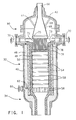
- the catalytic partial oxidation zone is typically the catalyst bed of a reactor such as that illustrated in Fig. 1.
- a reactor for partially oxidizing a gaseous feedstock includes an input mixing and distributor section indicated generally at 30.
- the mixer and distributor mixes the feedstock with an oxidant and distributes the mixture to the entrance of a catalytic reactor section indicated generally at 32 wherein the feedstock is partially oxidized to produce a product which is then passed through the exit section indicated generally at 34.
- the reactor includes an outer shell 40 of structural metal such as carbon steel with a top 42 secured thereon by bolts (not shown) or the like.
- a layer 43 of insulation such as 2300°F (1260°C) BPCF ceramic fiber insulation, is secured to the inside of the upper portion of the shell 40 including the top 42.
- the layer 46 is a castable or equivalent insulation such as 2000°F (1090°C) ceramic insulation.
- the layer 48 is also a castable or equivalent layer of insulation but containing 60% alumina for withstanding 3000°F (1650°C).
- the internal layer 50 is a refractory or equivalent layer such as 97% alumina with ceramic anchors or 97% alumina brick for withstanding the interior environment of the reactor section.
- the catalytic reactor section 32 contains one or more catalyst discs 54. As shown, the reactor contains a sequence of discs 54 separated by high alumina rings 58 between each adjacent pair of discs. The stack is supported by a grill with high alumina bars 56. A sample port 60 is formed in the lower end of the reaction section and has a tube, such as type 309 stainless steel tube 62 extending below the bottom refractory disc 54 for withdrawing samples of the product.
- the outlet section 34 is suitably formed for being connected to a downstream heat recovery boiler (not shown) and/or other processing equipment.
- the catalyst comprises a high surface area material capable of catalyzing the partial oxidation of the hydrocarbonaceous feedstock.
- the catalyst is in a configuration that provides a surface area to volume ratio of at least 5 cm2/cm3.
- the catalyst has a geometric surface area to volume ratio of at least 20 cm2/cm3. While there is no strict upper limit of 20 surface area to volume ratio, it normally does not exceed about 40 cm2/cm3.
- materials can be used in the construction of the catalyst including materials not normally considered to have catalytic activity, provided that the catalyst configuration has the desired surface area to volume ratio.
- the catalyst disc 54 can be, for example, a monolithic structure having a honeycomb type cross-sectional configuration. Suitable monolithic structures of this type are produced commercially, in sizes smaller than those used in the process of the invention, as structural substrates for use in the catalytic conversion of automobile exhausts and as catalytic combustion chambers of gas turbines or for catalytic oxidation of waste streams.
- the monolithic structure is an extruded material containing a plurality of closely packed channels running through the length of the structure to form a honeycomb structure. The channels are typically square and may be packed in a density as high as 186 per square centimeter of cross section.
- the monolithic structure can be constructed of any of a variety of materials, including cordierite (MgO/Al2O3/SiO2), Mn/MgO cordierite (Mn-MgO/Al2O3/SiO2), mullite (Al2O3/SiO2), mullite aluminum titanate (Al2O3/SiO2-(Al,Fe)2O3/TiO2), zirconia spinel (ZrO2/MgO/Al2O3), spinel (MgO/Al2O3), alumina (Al2O3) and igh nickel alloys.
- the monolithic catalyst may consist solely of any of these structural materials, even though these materials are not normally considered to have catalytic activity by themselves.
- the monolithic substrate can be coated with any of the metals or metal oxides known to have activity as oxidation catalysts. These include, for example, palladium, platinum, rhodium, irridium, osmium, ruthenium, nickel, chromium, cobalt, cerium, lanthanum and mixtures thereof.
- Other metals which can be used to coat the catalyst disc 54 include noble metals and metals of groups IA, IIA, III, IV, VB, VIB, or VIIB or the 25 periodic table of elements.
- the catalyst discs 54 may also consist of structural packing materials, such as that used in packing absorption columns. These packing materials generally comprise thin sheets of corrugated metal tightly packed together to form elongate channels running therethrough.
- the structural packing materials may consist of corrugated sheets of metals such as high temperature alloys, stainless steels, chromium, magnanese, molybdenum and refractory materials. These materials can, if desired, be coated with metals or metal oxides known to have catalytic activity for the oxidation reaction, such as palladium, platinum, rhodium, irridium, osmium, ruthenium, nickel, chromium, cobalt, cerium, lanthanum and mixtures thereof.
- the catalyst discs 54 can also consist of dense wire mesh, such as high temperature alloys or platinum mesh. If desired, the wire mesh can also be coated with a metal or metal oxide having catalytic activity for the oxidation reaction, including palladium, platinum, rhodium, irridium, osmium, ruthenium, nickel, chromium cobalt, cesium, lanthanum and mixtures thereof.
- a metal or metal oxide having catalytic activity for the oxidation reaction including palladium, platinum, rhodium, irridium, osmium, ruthenium, nickel, chromium cobalt, cesium, lanthanum and mixtures thereof.
- the surface area to volume ratio of any of the aforementioned catalyst configurations can be increased by coating the surfaces thereof with an aqueous slurry containing about 1% or less by weight or particulate metal or metal oxide such as alumina, or metals of groups IA, IIA, III, IV, VB, VIB and VIIB and firing the coated surface at high temperature to adhere the particulate metal to the surface, but not so high as to cause sintering of the surface.
- the particles employed should have a BET (Brunnauer-Emmett-Teller) surface area greater than about 10 m2/gram, preferably greater than about 200 m2/gram.
- a gaseous mixture of hydrocarbonaceous feedstock, oxygen or an oxygen-containing gas such as air, and, optionally, steam is introduced into the catalytic partial oxidation zone at a temperature not lower than 93°C below its autoignition temperature.
- the gaseous mixture enters the catalytic partial oxidation zone at a temperatue equal to or greater than its autoignition temperature. It is possible to operate the reactor in a mass transfer controlled mode with the reactants entering the reaction zone at a temperature somewhat below the autoignition temperature since the heat of reaction will provide the necessary energy to raise the reactant temperature within the reaction zone.
- the reactant mixture When the reactant mixture enters the catalytic partial oxidation zone at a temperature exceeding its autoignition temperature, it is necessary to introduce the mixture to the catalyst bed immediately after mixing; that is, the mixture of hydrocarbonaceous feedstock and oxidant should preferably be introduced to the catalyst bed before the autoignition delay time elapses. It is also essential that the gaseous reactants be thoroughly mixed. Failure to mix the reactants throughly reduces the quality of the product and can lead to overheating.
- a suitable apparatus for mixing and distributing the hydrocarbonaceous feedstock and oxygen or oxygen-containing gas so as to provide thorough mixing and to introduce the heated reactants into the reaction zone in a sufficiently short time is illustrated in Figs. 1-5.
- one of the feed gases i.e. hydrocarbonaceous gas or oxygen-containing gas
- the input section 30 is introduced into the input section 30 through a first inlet port 66 through the top 42 which communicates to an upper feed cone 68 which forms a first chamber.
- the cone 68 is fastened by supports 69 in the top 42.
- the other feed gas is introduced into the input section 30 through second inlets 70 extending through side ports of the shell 40 and communicating to a second chamber 72 which is interposed between the upper chamber 68 and the inlet of the catalyst reaction section 32.
- the chamber 72 has an upper outer annular portion 74, see also Figs. 2 and 3, which is supported on the top surface of the refractory layer 50.
- a lower portion of the chamber 72 has a tubular wall 76 which extends downward in the refractory sleeve 50.
- the bottom of the chamber 76 is formed by a cast member 78.
- steam can be introduced into either or both of the hydrocarbonaceous feedstock and oxygen or oxygen-containing gas, as indicated by the dotted arrows in Fig. 1.
- the gases are fed to the reactor in relative proportions such that the steam-to-carbon molar ratio is from 0:1 to 3.0:1, preferably from 0.3:1 to 2.0:1.
- the oxygen-to-carbon ratio is from 0.3:1 to 0.8:1, preferably from 0.45:1 to 0.65:1. If it is desired to use the resulting synthesis gas in the production of town gas, then the preferred oxygen-to-carbon molar ratio is from 0.3:1 to 0.65:1.
- the preferred oxygen-to-carbon molar ratio is from 0.4:1 to 0.8:1.
- the reactant mixture preferably enters the catalytic reactor section 32 at a temperature at or above its autoignition temperature. Depending on the particular proportions of reactant gases, the reactor operating pressure and the catalyst used, this will generally be between about 290°C and 590°C.
- hydrocarbonaceous feedstock and steam are admixed and heated to a temperature from 340°C to 650°C prior to passage through inlet port(s) 70 or 66.
- Oxygen or oxygen-containing gas, such as air is heated to a temperature from 65°C to 650°C and passes through the other inlet port(s) 66 or 70.
- the mixing and distributing means comprises a plurality of elongated tubes 80 having upper ends mounted in the upper wall 75 of the chamber 72.
- the lumens of the tubes at the upper end communicate with the upper chamber 68.
- the bottom ends of the tubes 80 are secured to the member 78 with the lumens of the tubes communicating with the upper ends of passageways 84 formed vertically through the member 78.
- Orifices 86 are formed in the walls of the tubes 80 for directing streams of gas from the chamber 72 into 15 the lumens of the tubes 80.
- the inlets 66 and 70, the cone 68, the supports 69 are formed from a conventional corrosion and heat resistant metal while the chamber 72, tubes 80 and member 78 are formed from a conventional high temperature alloy or refractory type material.
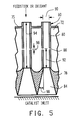
- the number of tubes 80, the internal diameter 90 (see Fig. 5) of the tubes 80, the size and number of the orifices 86 in each tube are selected relative to the gas input velocities and pressures through inlets 66 and 70 so as to produce turbulent flow within the tubes 80 at a velocity exceeding the flashback velocity of the mixture.
- the minimum distance 92 of the orifices 86 from the bottom end of the tube 80 at the opening into the diverging passageways 84 is selected to be equal to or greater than that required for providing substantially complete mixing of the gas streams from chamber 68 and 72 under the conditions of turbulence therein.
- the size of the internal diameter 90 of the tubes 80 as well as the length 94 of the tubes is designed to produce a sufficient pressure drop in the gas passing from the chamber 68 to the reaction chamber so as to provide for substantially uniform gas flow through the tubes 80 from the chamber 68.
- the size of the orifices 86 is selected to provide sufficient pressure drop between the chamber 72 and the interior of the tubes 80 relative to the velocity and pressures of the gas entering through inlets 70 so as to provide substantially uniform volumes of gas flows through the orifices 86 into the tubes 80.
- the diverging passageways in the member 78 are formed in a manner to provide for reduction of the velocity of the gas to produce uniform gas distribution over the inlet of the catalyst.
- the rate of increase of the cross-section of the passageway 84 as it proceeds downward, i.e., the angle 98 that the wall of the passageway 84 makes with the straight wall of the tubes 80, must generally be equal to or less than about 15° and preferably equal to or less than 7° in order to minimize or avoid creating vortices within the passageways 84. This assures that the essentially completely mixed gases, at a temperature near to or exceeding the autoignition temperature, will pass into the catalyst bed in a time preferably less that autoignition delay time.
- the configuration of the bottom end of the passageways, as shown in Fig. 4, is circular.
- the product gas exiting the outlet section 34 consists essentially of methane, carbon oxides, i.e. carbon monoxide and carbon dioxide, hydrogen and steam. Trace amounts of C2- and higher hydrocarbons may be present in the product gas. As used herein "trace amounts" means less than about 0.1% by weight.
- the catalytic partial oxidation reaction is preferably carried out in the catalytic reaction section 32 at a pressure greater than 690 KPa, more preferably at a pressure greater than 1724 KPa.
- the catalytic partial oxidation reaction is carried out at a temperature between about 760°C and 1090°C.
- Natural gas is converted to synthesis gas in a catalytic partial oxidation reactor of the construction shownin Fig. 1.
- the discs are included nine catalyst discs 54, each having a diameter of 30 inches (0.76m) and a thickness of 10 inches (0.25m).
- the discs are formed from a honeycomb monolith of cordierite material with a geometric surface area of approximately 25 cm2/cm3.
- a high surface area alumina layer is deposited on the cordierite to serve as a support upon which finely dispersed catalytic metal components are distended.
- the catalytic metal components are approximately 50% by weight platinum and 50% by weight palladium. Space velocity of the catalyst is 97,000 hr. ⁇ 1
- Natural gas (>95% methane) is mixed with steam at various steam-to-carbon molar ratios, heated and supplied through 25.4-centimeter diameter inlet 66 at a pressure of 2760 KPa. Air is heated and supplied through two 20.3-centimeter inlets 70 at a pressure of 2830 KPa.
- the diameter of the lower portion 76 of the chamber 72 is 27 inches (0.68m) with the diameter of the upper portion 74 being 36 inches (0.91m).
- each tube Six orifices 86 of 0.123-inch (3.2mm) diameter are formed in each tube with four of the orifices evenly spaced around each tube at a distance of 4 inches (0.102m) above the lower end of the tube and with the remaining two orifices formed opposite each other at a distance 6 inches (0.152m) above the lower end of the tube.
- the bottom member 78 has a thickness of 5 inches (0.127m) and the passageway sections 84 are conical with upper diameters of 0.5 inches (12.7 mm) and lower diameters of 1.75 inches (44.5mm). Pressures within the chambers 68 and 72 are maintained at essentially the inlet pressures.
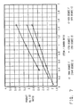
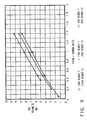
- the temperature of the mixed reactant gases is 590°C Fig. 6 shows oxygen consumption for the above process, as function of steam-to-carbon molar ratio, for reaction temperatures of 870°C, 950°C and 1040°C and an operating pressue of 2760 KPa. It can be seen from the graph that oxygen consumption, expressed as oxygen-to-carbon molar ratio, is relatively low for the process of the invention as compared with present commercial partial oxidation processes.
- FIG. 6 represents the conditions under which carbon deposits are formed, and particularly, shows a generally linear function of temperature with respect to the steam-to-carbon molar ratio, including the range of 1040°C for a steam-to-carbon molar ratio of 0:1 to 870°C for a steam-to-carbon molar ratio of 0.4:1.
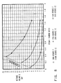
- Fig. 7 shows the molar ratio of hydrogen, as H2, to carbon monoxide in the product as a function of steam-to-carbon ratio for reaction temperatures of 870°C, 950°C and 1040°C.
- Figs. 8 and 9 respectively, show the amounts of methane and carbon dioxide, as volume %, in the product as a function of steam-to-carbon ratio for reaction temperatures of 870°C, 950°C and 1040°C.
- Fig. 10 shows the effective H2 production of the process, expressed as total moles of H2 and carbon monoxide in the product divided by total moles of H2 and carbon in the feedstock.
- Figs. 6-10 show that the process of the invention is capable of producing synthesis gas of a high level of efficiency and at low oxygen demand, using relatively low oxidation temperatures and relatively inexpensive catalyst materials.
Abstract
Description
- The present invention relates to the production of synthesis gas from gaseous or vaporizable hydrocarbonaceous feedstocks. In particular, the invention relates to the preparation of synthesis gas by the catalytic partial oxidation of hydrocarbonaceous feedstocks under conditions which allow efficient conversion at relatively low temperatures and low oxygen demand. Furthermore, the process of the invention uses equipment which is less expensive than equipment previously employed in the oxidation of hydrocarbonaceous feedstocks.
- The conversion of hydrocarbonaceous feedstocks, such as natural gases recovered from sites near petroleum deposits, into industrially useful gases has been practiced for many years. Typically, such gases contain, as their major components, methane, ethane, propane and butane. Also included in the conversion, in some instances, may be low-boiling liquid hydrocarbons.
- In order to convert hydrocarbonaceous feedstocks into industrially useful products such as ammonia, carbon monoxide, methanol, hydrogen and town gas, the feedstock is first converted into so-called synthesis gas, the principal constituents of which are carbon monoxide, hydrogen, methane and carbon dioxide. The synthesis gas is then subjected to a number of separation and/or conversion processes to obtain the desired end products.
- The most commonly employed method for converting hydrocarbonaceous feedstocks to synthesis gas has been catalytic reforming. In this process, the hydrocarbonaceous feedstock is reacted with steam in the presence of a catalyst, usually a nickel-containing catalyst, at temperatures between about 650°C and 1040°C. The hydrocarbons react with steam under these conditions to produce carbon monoxide and hydrogen. Catalytic steam reforming is an expensive process to carry out. Not only is the nickel containing catalyst very expensive, but also, the reactions are highly endothermic. Consequently, a great deal of energy must be provided to drive the reaction to the desired products. Frequently, air is provided to the reforming reaction in order to provide energy through partial oxidation of hydrocarbons.
- Partial oxidation of hydrocarbonaceous feedstocks represents one alternative to steam reforming in the production of synthesis gas. Most of the partial oxidation processes that have been employed commercially are non-catalytic processes. Non-catalytic partial oxidation reactions however, are relatively inefficient. They operate at high temperatures, i.e., in the range of 1,200°C to 1,540C° and require large amounts of oxygen. Typically, the oxygen-to-carbon ratio required in non-catalytic partial oxidation is greater than 0.8:1 and often greater than 1:1.
- U.S. Patent 4,390,347 issued to Dille et al. describes a process for the production of synthesis gas by the non-catalytic partial oxidation of a liquid hydrocarbonaceous fuel. The hydrocarbonaceous feedstock is reacted with a free oxygen-containing gas in the presence of steam at an autogenously maintained temperature within the range of 925°C to 1650°C at a pressure in the range of about 100 to 2300 KPa absolute. The oxygen-to-carbon molar ratio is said to be from 0.7:1 to 1.5:1.
- U.S. Patent 3,890,113 issued to Child et al., describes the production of a methane-rich stream in which non-catalytic partial oxidation of a hydrocarbonaceous feedstock is carried out in the presence of steam and oxygen. The ratio of free oxygen in the oxidant to carbon in the feedstock is in the range of 0.8:1 to 1.5:1. The product synthesis gas is subjected to a water gas shift reaction to increase the amount of hydrogen in the gas.
- U.S. Patent 3,927,998 issued to Child et al., relates to the production of a methane rich stream by the partial oxidation of the hydrocarbonaceous fuel employing a steam to fuel weight ratio of 2.2:1 to 2.9:1 and an oxygen-to-carbon molar ratio of 0.8:1 to 0.84:1. The partial oxidation is carried out in the absence of catalysts. The synthesis gas is cooled and water, carbon dioxide, carbon and other impurities are removed. The hydrogen and carbon monoxide in the gas are reacted in a catalytic methanation zone to produce a methane-rich stream.
- Conversion efficiency of partial oxidation processes can be improved by the use of catalysts. However, catalytic partial oxidation processes of the prior art generally employ very expensive catalyst materials. For example, U.S. Patent 4,087,259, issued to Fujitani et al., describes a process wherein a liquid hydrocarbonaceous feedstock is vaporized and then partially oxidized in contact with a catalyst consisting of rhodium supported on a carrier.
- The use of catalysts in partial oxidation processes requires that the reaction be carried out within a specific range of "space velocity". Space velocity may be defined as the volumetric hourly rate of throughput per volume of catalyst. All figures guoted herein refer to the volumetric hourly rate at standard conditions of temperature and pressure. In order to obtain acceptable levels of conversion using catalytic partial oxidation processes of the prior art it has been necessary to use space velocities below about 12,000 hr.⁻¹ For example, U.S. Patent No. 4,522,894, issued to Hwang et al., describes the production of a hydrogen-rich gas to be used as fuel for the fuel cell. The process reacts a hydrocarbon feed with steam and an oxidant in an autothermal reformer using 2 catalyst zones. The total hourly space velocity is between 1,960 hr⁻¹ and 18,000 hr.⁻¹. Because the prior art processes must be carried out at low space velocity, catalytic partial oxidation reactors of the prior art have had to have large catalyst beds in order to achieve the throughputs desired in commercial operation. This increases the size and cost of the partial oxidation reactor.
- It is an object of the present invention to provide a catalytic partial oxidation process which allows for the efficient conversion of hydrocarbonaceous feedstocks to synthesis gas at relatively high space velocities, on the order of about 20,000 hr.⁻¹ or higher, so that the size of the catalyst bed and the partial oxidation reactor can be kept to a minimum while still obtaining commercially acceptable throughputs.
- It is a further object of the present invention to provide a catalytic partial oxidation process which converts hydrocarbonaceous feedstocks to synthesis gas with a relatively low oxygen demand, thereby increasing throughput of hydrocarbonaceous feedstocks.
- It is yet a further object of the invention to provide a catalytic partial oxidation process which allows for the use of relatively inexpensive catalysts.
- The present invention provides a catalytic partial oxidation process for converting gaseous or vaporizable hydrocarbonaceous feedstock to synthesis gas. The process of the invention operates efficiently at low oxygen demand. The processing conditions and type of catalyst employed allow the process to be carried out at high space velocity.
- The process of the invention comprises:
- (a) introducing to a catalytic partial oxidation zone a gaseous mixture of a hydrocarbonaceous feedstock, oxygen or an oxygen-containing gas and, optionally, steam in which the steam-to-carbon molar ratio is from 0:1 to 3.0:1 and the oxygen-to-carbon molar ratio is from 0.3:1 to 0.8:1, said mixture being introduced to the catalytic partial oxidation zone at a temperature not lower than 93°C below its autoignition temperature and preferably at or above its autoignition temperature; and
- (b) partially oxidizing the hydrocarbonaceous feedstock in the catalytic partial oxidation zone to produce a gas consisting essentially of methane carbon oxides, hydrogen and steam by passing the mixture through a catalyst capable of catalyzing the oxidation of the hydrocarbons, said catalyst having a ratio of surface area to volume of at least 5 cm²/cm³.
- The process of the invention can be carried out using, as a catalyst, inexpensive materials not previously considered to have useful catalytic activity.
- The process can be carried out at high space velocities, on the order of 20,000 hr.⁻¹ to 500,000 hr.⁻¹ thus allowing for high throughputs using a relatively small catalytic partial oxidation reactor.
-
- Fig. 1 is an elevated cross-section view of a reactor having at its input a mixer and distributor suitable for introducing the reactants to the catalyst bed.
- Fig. 2 is an enlarged elevational cross-section view of a broken-away portion of the mixer and distributor of Fig. 1.
- Fig. 3 is a top view of a broken-away quarter section of the mixer and distributor of Fig. 1.
- Fig. 4 is a bottom view of a broken-away quarter section of the mixer and distributor of Fig. 1.
- Fig. 5 is a diagrammatic elevational cross-sectional illustration of a broken-away portion of the mixer and feeder of Figs. 1 and 2 showing critical dimensions.
- Fig. 6 is a graph plotting oxygen-to-carbon molar ratios vs. steam-to-carbon molar ratio for three different operating temperatures at an operating pressure of 2760 KPa.
- Fig. 7 is a graph plotting the hydrogen-to-carbon monoxide molar ratio in the catalytic partial oxidation reaction product vs. The steam-to-carbon molar ratio for three different operating temperatures at an operating pressure of 2760 KPa.
- Fig. 8 is a graph plotting the volume % methane in the catalytic partial oxidation product vs. the steam-to-carbon molar ratio for three different operating temperatures at an operating pressure of 2760 KPa.
- Fig. 9 is a graph plotting the volume % carbon dioxide in the catalytic partial oxidation product for three different operating temperatures at an operating pressure of 2760 KPa.
- Fig. 10 is a graph plotting the molar ratio of total hydrogen and carbon monoxide in the product to total hydrogen and carbon in the feedstock for three different operating temperatures at an operating pressure of 2760 KPa.
- The process of the present invention can be used to produce synthesis gas from any gaseous or low-boiling hydrocarbonaceous feedstock. Typically, a gaseous hydrocarbonaceous feedstock used to produce synthesis gas is natural gas having the following approximate composition: methane, 93%; ethane, 5%; propane 1.5%; butane and higher hydrocarbons, 0.5%.
- Little reforming reactions take place in the process of the invention; that is, the process of the invention relies essentially on partial oxidation to convert hydrocarbonaceous feedstock to synthesis gas. The process of the invention can be employed to convert hydrocarbonaceous feedstock to synthesis gas, in the absence of reforming reactions, with very low levels of hydrocarbon slippage (unreacted feedstock), i.e. as low as 2% or lower, if desired. For some end uses, e.g. the production of town gas, it may be desired to allow significantly higher levels of hydrocarbon slippage and this can also be accomplished in accordance with the process of the invention. Because the rate of conversion in the partial oxidation reaction can be mass transfer controlled independently of the chemical nature of the catalyst employed, the process of the invention can be carried out efficiently using relatively inexpensive catalyst materials, provided that the surface area-to volume requirements of the invention are met.
- In accordance with the process of the invention the reactant gases are introduced to the reaction zone, i.e. the catalyst bed, at an inlet temperature not lower than 93°C less than the autoignition temperature of the feed mixture. Preferably the reactant gases are introduced at a temperature at or above the autoignition temperature of the mixture. A further essential feature of the invention is that the reactants shall be completely mixed prior to the reaction. Introducing the thoroughly mixed reactant gases at the proper temperature ensures that the partial oxidation reactions will be mass transfer controlled. Consequently, the reaction rate is relatively independent of catalyst activity, but dependent on the surface-area-to-volume ratio of the catalyst. It is possible to use any of a wide variety of materials as a catalyst, provided that the catalyst has the desired surface-area-to-volume ratio. It is not necessary that the catalyst have specific catalytic activity for the steam reforming reaction. Even materials normally considered to be non-catalytic can promote the production of synthesis gas under the reaction conditions specified herein when used as a catalyst in the proper configuration. The term "catalyst", as used herein, is intended to encompass such materials.
- The process of the invention can be understood with reference to the figures. The catalytic partial oxidation zone is typically the catalyst bed of a reactor such as that illustrated in Fig. 1. As shown in Fig. 1, a reactor for partially oxidizing a gaseous feedstock includes an input mixing and distributor section indicated generally at 30. The mixer and distributor mixes the feedstock with an oxidant and distributes the mixture to the entrance of a catalytic reactor section indicated generally at 32 wherein the feedstock is partially oxidized to produce a product which is then passed through the exit section indicated generally at 34.
- The reactor includes an
outer shell 40 of structural metal such as carbon steel with a top 42 secured thereon by bolts (not shown) or the like. A layer 43 of insulation, such as 2300°F (1260°C) BPCF ceramic fiber insulation, is secured to the inside of the upper portion of theshell 40 including the top 42. In the lower portion of the mixingsection 30 in thereactor section 32 andoutlet section 34, there aresecured layers layer 46 is a castable or equivalent insulation such as 2000°F (1090°C) ceramic insulation. Thelayer 48 is also a castable or equivalent layer of insulation but containing 60% alumina for withstanding 3000°F (1650°C). Theinternal layer 50 is a refractory or equivalent layer such as 97% alumina with ceramic anchors or 97% alumina brick for withstanding the interior environment of the reactor section. - The
catalytic reactor section 32 contains one ormore catalyst discs 54. As shown, the reactor contains a sequence ofdiscs 54 separated by high alumina rings 58 between each adjacent pair of discs. The stack is supported by a grill with high alumina bars 56. Asample port 60 is formed in the lower end of the reaction section and has a tube, such as type 309stainless steel tube 62 extending below the bottomrefractory disc 54 for withdrawing samples of the product. - The
outlet section 34 is suitably formed for being connected to a downstream heat recovery boiler (not shown) and/or other processing equipment. - The catalyst comprises a high surface area material capable of catalyzing the partial oxidation of the hydrocarbonaceous feedstock. The catalyst is in a configuration that provides a surface area to volume ratio of at least 5 cm²/cm³. Preferably, the catalyst has a geometric surface area to volume ratio of at least 20 cm²/cm³. While there is no strict upper limit of 20 surface area to volume ratio, it normally does not exceed about 40 cm²/cm³. A wide variety of materials can be used in the construction of the catalyst including materials not normally considered to have catalytic activity, provided that the catalyst configuration has the desired surface area to volume ratio.
- The
catalyst disc 54 can be, for example, a monolithic structure having a honeycomb type cross-sectional configuration. Suitable monolithic structures of this type are produced commercially, in sizes smaller than those used in the process of the invention, as structural substrates for use in the catalytic conversion of automobile exhausts and as catalytic combustion chambers of gas turbines or for catalytic oxidation of waste streams. Typically, the monolithic structure is an extruded material containing a plurality of closely packed channels running through the length of the structure to form a honeycomb structure. The channels are typically square and may be packed in a density as high as 186 per square centimeter of cross section. The monolithic structure can be constructed of any ofa variety of materials, including cordierite (MgO/Al₂O₃/SiO₂), Mn/MgO cordierite (Mn-MgO/Al₂O₃/SiO₂), mullite (Al₂O₃/SiO₂), mullite aluminum titanate (Al₂O₃/SiO₂-(Al,Fe)₂O₃/TiO₂), zirconia spinel (ZrO₂/MgO/Al₂O₃), spinel (MgO/Al₂O₃), alumina (Al₂O₃) and igh nickel alloys. The monolithic catalyst may consist solely of any of these structural materials, even though these materials are not normally considered to have catalytic activity by themselves. Using honeycombed substrates, surface area to volume ratios up to 40 cm²/cm³ or higher can be obtained. Alternatively, the monolithic substrate can be coated with any of the metals or metal oxides known to have activity as oxidation catalysts. These include, for example, palladium, platinum, rhodium, irridium, osmium, ruthenium, nickel, chromium, cobalt, cerium, lanthanum and mixtures thereof. Other metals which can be used to coat thecatalyst disc 54 include noble metals and metals of groups IA, IIA, III, IV, VB, VIB, or VIIB or the 25 periodic table of elements. - The
catalyst discs 54 may also consist of structural packing materials, such as that used in packing absorption columns. These packing materials generally comprise thin sheets of corrugated metal tightly packed together to form elongate channels running therethrough. The structural packing materials may consist of corrugated sheets of metals such as high temperature alloys, stainless steels, chromium, magnanese, molybdenum and refractory materials. These materials can, if desired, be coated with metals or metal oxides known to have catalytic activity for the oxidation reaction, such as palladium, platinum, rhodium, irridium, osmium, ruthenium, nickel, chromium, cobalt, cerium, lanthanum and mixtures thereof. - The
catalyst discs 54 can also consist of dense wire mesh, such as high temperature alloys or platinum mesh. If desired, the wire mesh can also be coated with a metal or metal oxide having catalytic activity for the oxidation reaction, including palladium, platinum, rhodium, irridium, osmium, ruthenium, nickel, chromium cobalt, cesium, lanthanum and mixtures thereof. - The surface area to volume ratio of any of the aforementioned catalyst configurations can be increased by coating the surfaces thereof with an aqueous slurry containing about 1% or less by weight or particulate metal or metal oxide such as alumina, or metals of groups IA, IIA, III, IV, VB, VIB and VIIB and firing the coated surface at high temperature to adhere the particulate metal to the surface, but not so high as to cause sintering of the surface. The particles employed should have a BET (Brunnauer-Emmett-Teller) surface area greater than about 10 m²/gram, preferably greater than about 200 m²/gram.
- In the practice of the invention, a gaseous mixture of hydrocarbonaceous feedstock, oxygen or an oxygen-containing gas such as air, and, optionally, steam is introduced into the catalytic partial oxidation zone at a temperature not lower than 93°C below its autoignition temperature. Preferably, the gaseous mixture enters the catalytic partial oxidation zone at a temperatue equal to or greater than its autoignition temperature. It is possible to operate the reactor in a mass transfer controlled mode with the reactants entering the reaction zone at a temperature somewhat below the autoignition temperature since the heat of reaction will provide the necessary energy to raise the reactant temperature within the reaction zone. In such a case, however, it will generally be necessary to provide heat input at the entrance to the reaction zone, for example by a sparking device, or by preheating the contents of the reactor, including the catalyst, to a temperature in excess of the autoignition temperature prior to the introducing of the reactants to initiate the reaction. If the reactant temperature at the input to the reaction zone is lower than the autoignition temperature by more than about 93°C, the reaction becomes unstable.
- When the reactant mixture enters the catalytic partial oxidation zone at a temperature exceeding its autoignition temperature, it is necessary to introduce the mixture to the catalyst bed immediately after mixing; that is, the mixture of hydrocarbonaceous feedstock and oxidant should preferably be introduced to the catalyst bed before the autoignition delay time elapses. It is also essential that the gaseous reactants be thoroughly mixed. Failure to mix the reactants throughly reduces the quality of the product and can lead to overheating. A suitable apparatus for mixing and distributing the hydrocarbonaceous feedstock and oxygen or oxygen-containing gas so as to provide thorough mixing and to introduce the heated reactants into the reaction zone in a sufficiently short time is illustrated in Figs. 1-5.
- Referring to Fig. 1, one of the feed gases, i.e. hydrocarbonaceous gas or oxygen-containing gas, is introduced into the
input section 30 through afirst inlet port 66 through the top 42 which communicates to anupper feed cone 68 which forms a first chamber. Thecone 68 is fastened bysupports 69 in the top 42. The other feed gas is introduced into theinput section 30 throughsecond inlets 70 extending through side ports of theshell 40 and communicating to asecond chamber 72 which is interposed between theupper chamber 68 and the inlet of thecatalyst reaction section 32. Aring 73 mounted 5 on the central portion of anupper wall 75 of thechamber 72 sealingly engages the lower edge of thecone 68 so that the wall 82 forms a common wall between theupper chamber 68 andlower chamber 72. Thechamber 72 has an upper outerannular portion 74, see also Figs. 2 and 3, which is supported on the top surface of therefractory layer 50. A lower portion of thechamber 72 has atubular wall 76 which extends downward in therefractory sleeve 50. The bottom of thechamber 76 is formed by acast member 78. - Optionally, steam can be introduced into either or both of the hydrocarbonaceous feedstock and oxygen or oxygen-containing gas, as indicated by the dotted arrows in Fig. 1. The gases are fed to the reactor in relative proportions such that the steam-to-carbon molar ratio is from 0:1 to 3.0:1, preferably from 0.3:1 to 2.0:1. The oxygen-to-carbon ratio is from 0.3:1 to 0.8:1, preferably from 0.45:1 to 0.65:1. If it is desired to use the resulting synthesis gas in the production of town gas, then the preferred oxygen-to-carbon molar ratio is from 0.3:1 to 0.65:1. For most other uses, such as the production of ammonia, methanol, hydrogen and carbon monoxide, the preferred oxygen-to-carbon molar ratio is from 0.4:1 to 0.8:1.
- The reactant mixture preferably enters the
catalytic reactor section 32 at a temperature at or above its autoignition temperature. Depending on the particular proportions of reactant gases, the reactor operating pressure and the catalyst used, this will generally be between about 290°C and 590°C. Preferably, hydrocarbonaceous feedstock and steam are admixed and heated to a temperature from 340°C to 650°C prior to passage through inlet port(s) 70 or 66. Oxygen or oxygen-containing gas, such as air, is heated to a temperature from 65°C to 650°C and passes through the other inlet port(s) 66 or 70. - Referring to Fig. 2, the mixing and distributing means comprises a plurality of
elongated tubes 80 having upper ends mounted in theupper wall 75 of thechamber 72. The lumens of the tubes at the upper end communicate with theupper chamber 68. The bottom ends of thetubes 80 are secured to themember 78 with the lumens of the tubes communicating with the upper ends ofpassageways 84 formed vertically through themember 78.Orifices 86 are formed in the walls of thetubes 80 for directing streams of gas from thechamber 72 into 15 the lumens of thetubes 80. Theinlets cone 68, thesupports 69 are formed from a conventional corrosion and heat resistant metal while thechamber 72,tubes 80 andmember 78 are formed from a conventional high temperature alloy or refractory type material. - The number of
tubes 80, the internal diameter 90 (see Fig. 5) of thetubes 80, the size and number of theorifices 86 in each tube are selected relative to the gas input velocities and pressures throughinlets tubes 80 at a velocity exceeding the flashback velocity of the mixture. Theminimum distance 92 of theorifices 86 from the bottom end of thetube 80 at the opening into the divergingpassageways 84 is selected to be equal to or greater than that required for providing substantially complete mixing of the gas streams fromchamber internal diameter 90 of thetubes 80 as well as thelength 94 of the tubes is designed to produce a sufficient pressure drop in the gas passing from thechamber 68 to the reaction chamber so as to provide for substantially uniform gas flow through thetubes 80 from thechamber 68. Likewise the size of theorifices 86 is selected to provide sufficient pressure drop between thechamber 72 and the interior of thetubes 80 relative to the velocity and pressures of the gas entering throughinlets 70 so as to provide substantially uniform volumes of gas flows through theorifices 86 into thetubes 80. - The diverging passageways in the
member 78 are formed in a manner to provide for reduction of the velocity of the gas to produce uniform gas distribution over the inlet of the catalyst. The rate of increase of the cross-section of thepassageway 84 as it proceeds downward, i.e., theangle 98 that the wall of thepassageway 84 makes with the straight wall of thetubes 80, must generally be equal to or less than about 15° and preferably equal to or less than 7° in order to minimize or avoid creating vortices within thepassageways 84. This assures that the essentially completely mixed gases, at a temperature near to or exceeding the autoignition temperature, will pass into the catalyst bed in a time preferably less that autoignition delay time. The configuration of the bottom end of the passageways, as shown in Fig. 4, is circular. - The product gas exiting the
outlet section 34 consists essentially of methane, carbon oxides, i.e. carbon monoxide and carbon dioxide, hydrogen and steam. Trace amounts of C₂- and higher hydrocarbons may be present in the product gas. As used herein "trace amounts" means less than about 0.1% by weight. - The catalytic partial oxidation reaction is preferably carried out in the
catalytic reaction section 32 at a pressure greater than 690 KPa, more preferably at a pressure greater than 1724 KPa. The catalytic partial oxidation reaction is carried out at a temperature between about 760°C and 1090°C. - Natural gas is converted to synthesis gas in a catalytic partial oxidation reactor of the construction shownin Fig. 1. There are included nine
catalyst discs 54, each having a diameter of 30 inches (0.76m) and a thickness of 10 inches (0.25m). The discs are formed from a honeycomb monolith of cordierite material with a geometric surface area of approximately 25 cm²/cm³. A high surface area alumina layer is deposited on the cordierite to serve as a support upon which finely dispersed catalytic metal components are distended. The catalytic metal components are approximately 50% by weight platinum and 50% by weight palladium. Space velocity of the catalyst is 97,000 hr.⁻¹ - Natural gas (>95% methane) is mixed with steam at various steam-to-carbon molar ratios, heated and supplied through 25.4-
centimeter diameter inlet 66 at a pressure of 2760 KPa. Air is heated and supplied through two 20.3-centimeter inlets 70 at a pressure of 2830 KPa. The diameter of thelower portion 76 of thechamber 72 is 27 inches (0.68m) with the diameter of theupper portion 74 being 36 inches (0.91m). There are 261tubes 80 having 0.5 inch (12.7mm) internal diameters and having lengths of 20 inches (0.51m). Sixorifices 86 of 0.123-inch (3.2mm) diameter are formed in each tube with four of the orifices evenly spaced around each tube at a distance of 4 inches (0.102m) above the lower end of the tube and with the remaining two orifices formed opposite each other at adistance 6 inches (0.152m) above the lower end of the tube. Thebottom member 78 has a thickness of 5 inches (0.127m) and thepassageway sections 84 are conical with upper diameters of 0.5 inches (12.7 mm) and lower diameters of 1.75 inches (44.5mm). Pressures within thechambers - The temperature of the mixed reactant gases is 590°C Fig. 6 shows oxygen consumption for the above process, as function of steam-to-carbon molar ratio, for reaction temperatures of 870°C, 950°C and 1040°C and an operating pressue of 2760 KPa. It can be seen from the graph that oxygen consumption, expressed as oxygen-to-carbon molar ratio, is relatively low for the process of the invention as compared with present commercial partial oxidation processes. The dashed
line 25 in Fig. 6 represents the conditions under which carbon deposits are formed, and particularly, shows a generally linear function of temperature with respect to the steam-to-carbon molar ratio, including the range of 1040°C for a steam-to-carbon molar ratio of 0:1 to 870°C for a steam-to-carbon molar ratio of 0.4:1. - Fig. 7 shows the molar ratio of hydrogen, as H₂, to carbon monoxide in the product as a function of steam-to-carbon ratio for reaction temperatures of 870°C, 950°C and 1040°C.
- Figs. 8 and 9, respectively, show the amounts of methane and carbon dioxide, as volume %, in the product as a function of steam-to-carbon ratio for reaction temperatures of 870°C, 950°C and 1040°C.
- Fig. 10 shows the effective H₂ production of the process, expressed as total moles of H₂ and carbon monoxide in the product divided by total moles of H₂ and carbon in the feedstock.
- Figs. 6-10 show that the process of the invention is capable of producing synthesis gas of a high level of efficiency and at low oxygen demand, using relatively low oxidation temperatures and relatively inexpensive catalyst materials. As those skilled in the art will be aware, numerous variations of the foregoing example will be possible within the scope of the invention. This example is intended only to illustrate the process of the invention and is not intended to limit its scope in any way.
Claims (20)
Applications Claiming Priority (2)
| Application Number | Priority Date | Filing Date | Title |
|---|---|---|---|
| US8516087A | 1987-08-14 | 1987-08-14 | |
| US85160 | 1987-08-14 |
Publications (2)
| Publication Number | Publication Date |
|---|---|
| EP0303438A2 true EP0303438A2 (en) | 1989-02-15 |
| EP0303438A3 EP0303438A3 (en) | 1989-12-27 |
Family
ID=22189839
Family Applications (1)
| Application Number | Title | Priority Date | Filing Date |
|---|---|---|---|
| EP88307342A Withdrawn EP0303438A3 (en) | 1987-08-14 | 1988-08-09 | Production of synthesis gas from hydrocarbonaceous feedstock |
Country Status (13)
| Country | Link |
|---|---|
| EP (1) | EP0303438A3 (en) |
| JP (1) | JPH01145301A (en) |
| KR (1) | KR890003621A (en) |
| CN (1) | CN1013430B (en) |
| AR (1) | AR244176A1 (en) |
| AU (1) | AU610219B2 (en) |
| BR (1) | BR8804093A (en) |
| DK (1) | DK453388A (en) |
| IN (1) | IN171834B (en) |
| NO (1) | NO172886C (en) |
| NZ (1) | NZ225819A (en) |
| RU (1) | RU1831468C (en) |
| ZA (1) | ZA885994B (en) |
Cited By (107)
| Publication number | Priority date | Publication date | Assignee | Title |
|---|---|---|---|---|
| WO1990006282A1 (en) * | 1988-11-30 | 1990-06-14 | Davy Mckee Corporation | Production of methanol from hydrocarbonaceous feedstock |
| WO1990006281A1 (en) * | 1988-11-30 | 1990-06-14 | Davy Mckee Corporation | Production of ammonia from hydrocarbonaceous feedstock |
| WO1991004222A1 (en) * | 1989-09-20 | 1991-04-04 | Gosudarstvenny Nauchno-Issledovatelsky I Proektny Institut Azotnoi Promyshlennosti I Produktov Organicheskogo Sinteza | Method for obtaining hydrogen-containing gas |
| US5149464A (en) * | 1989-06-30 | 1992-09-22 | Gas Research Institute | Catalytic gas conversion method |
| FR2684313A1 (en) * | 1991-12-03 | 1993-06-04 | Inst Francais Du Petrole | METHOD AND DEVICE FOR THE MANUFACTURE OF SYNTHESIS GAS AND. |
| EP0576096A2 (en) * | 1992-06-24 | 1993-12-29 | Shell Internationale Researchmaatschappij B.V. | Process for the catalytic partial oxidation of hydrocarbons |
| GB2274284A (en) * | 1992-12-23 | 1994-07-20 | Snam Progetti | Catalytic process for producing synthesis gas |
| EP0640559A1 (en) * | 1993-08-27 | 1995-03-01 | SNAMPROGETTI S.p.A. | Process of catalytic partial oxidation of natural gas in order to obtain synthesis gas and formaldehyde |
| EP0656317A1 (en) * | 1993-11-29 | 1995-06-07 | Shell Internationale Researchmaatschappij B.V. | Process for the catalytic partial oxidation of hydrocarbons |
| WO1995018062A1 (en) * | 1993-12-27 | 1995-07-06 | Shell Internationale Research Maatschappij B.V. | Process for the catalytic partial oxidation of hydrocarbons |
| WO1995018063A1 (en) * | 1993-12-27 | 1995-07-06 | Shell Internationale Research Maatschappij B.V. | A process for the preparation of carbon monoxide and/or hydrogen |
| US5654491A (en) * | 1996-02-09 | 1997-08-05 | Regents Of The University Of Minnesota | Process for the partial oxidation of alkanes |
| WO1997037929A1 (en) * | 1996-04-11 | 1997-10-16 | Snamprogetti S.P.A. | Equipment for partial oxidation reactions |
| WO1998049095A1 (en) * | 1997-04-25 | 1998-11-05 | Exxon Research And Engineering Company | Distributed injection catalytic partial oxidation process and apparatus for producing synthesis gas |
| WO1998049094A1 (en) * | 1997-04-25 | 1998-11-05 | Exxon Research And Engineering Company | Rapid injection catalytic partial oxidation process and apparatus for producing synthesis gas |
| DE19727841A1 (en) * | 1997-06-24 | 1999-01-07 | Fraunhofer Ges Forschung | Method and device for the autothermal reforming of hydrocarbons |
| US5886056A (en) * | 1997-04-25 | 1999-03-23 | Exxon Research And Engineering Company | Rapid injection process and apparatus for producing synthesis gas (law 560) |
| EP0906890A1 (en) * | 1997-10-02 | 1999-04-07 | dbb fuel cell engines GmbH | Apparatus for the generation of hydrogen, apparatus for reduction of carbon monoxide content, apparatus for oxidation of carbon monoxide, apparatus for catalytic burning and method for the production of a catalyst |
| US5935489A (en) * | 1997-04-25 | 1999-08-10 | Exxon Research And Engineering Co. | Distributed injection process and apparatus for producing synthesis gas |
| US5980596A (en) * | 1997-04-25 | 1999-11-09 | Exxon Research And Engineering Co. | Multi-injector autothermal reforming process and apparatus for producing synthesis gas (law 565). |
| US5980782A (en) * | 1997-04-25 | 1999-11-09 | Exxon Research And Engineering Co. | Face-mixing fluid bed process and apparatus for producing synthesis gas |
| WO2001032556A1 (en) * | 1999-10-29 | 2001-05-10 | Exxon Research And Engineering Company | Process for catalytic partial oxidation using particulate catalysts |
| US6293979B1 (en) | 1994-12-19 | 2001-09-25 | Council Of Scientific & Industrial Research | Process for the catalytic conversion of methane or natural gas to syngas or a mixture of carbon monoxide and hydrogen |
| DE10025032A1 (en) * | 2000-05-20 | 2001-11-29 | Dmc2 Degussa Metals Catalysts | Process for the autothermal, catalytic steam reforming of hydrocarbons |
| US6333294B1 (en) | 1998-05-22 | 2001-12-25 | Conoco Inc. | Fischer-tropsch processes and catalysts with promoters |
| WO2002008119A1 (en) * | 2000-07-25 | 2002-01-31 | Conoco, Inc. | Spox-enhanced process for production of synthesis gas |
| WO2002030811A1 (en) * | 2000-10-09 | 2002-04-18 | Semen Evseevich Piskunov | Method for producing a synthesis gas |
| US6402989B1 (en) | 1999-07-30 | 2002-06-11 | Conoco Inc. | Catalytic partial oxidation process and promoted nickel based catalysts supported on magnesium oxide |
| US6458334B1 (en) | 2000-03-02 | 2002-10-01 | The Boc Group, Inc. | Catalytic partial oxidation of hydrocarbons |
| US6488907B1 (en) | 1999-07-30 | 2002-12-03 | Conoco Inc. | Catalytic partial oxidation processes and catalysts with diffusion barrier coating |
| WO2002096839A1 (en) | 2001-05-25 | 2002-12-05 | Bp Exploration Operaing Company Limited | Fischer-tropsch process |
| DE10157155A1 (en) * | 2001-11-22 | 2003-06-12 | Omg Ag & Co Kg | Process for the catalytic autothermal steam reforming of higher alcohols, especially ethanol |
| US6630078B2 (en) * | 2000-02-18 | 2003-10-07 | Conocophillips Company | Reticulated ceramic foam catalysts for synthesis gas production |
| US6635191B2 (en) | 2000-06-13 | 2003-10-21 | Conocophillips Company | Supported nickel-magnesium oxide catalysts and processes for the production of syngas |
| US6673270B1 (en) | 1997-10-14 | 2004-01-06 | Shell Oil Company | Process for the preparation of hydrogen and carbon monoxide |
| US6692707B1 (en) | 1999-03-03 | 2004-02-17 | Toyota Jidosha Kabushiki Kaisha | Hydrocarbon fuel reformer |
| US6733692B2 (en) | 2000-04-20 | 2004-05-11 | Conocophillips Company | Rhodium foam catalyst for the partial oxidation of hydrocarbons |
| US6746658B2 (en) | 2000-04-20 | 2004-06-08 | Conocophillips Company | Rhodium cloth catalyst for partial oxidation of hydrocarbons |
| US6783749B2 (en) | 2002-05-13 | 2004-08-31 | The Boc Group, Inc. | Gas recovery process |
| EP1496040A1 (en) | 1999-11-26 | 2005-01-12 | Bp Exploration Operating Company Limited | Process for converting synthesis gas into higher hydrocarbons |
| US6911161B2 (en) | 2002-07-02 | 2005-06-28 | Conocophillips Company | Stabilized nickel-containing catalysts and process for production of syngas |
| US6946114B2 (en) | 2000-09-05 | 2005-09-20 | Conocophillips Company | Lanthanide-promoted rhodium catalysts and process for producing synthesis gas |
| US7008597B1 (en) | 1998-12-29 | 2006-03-07 | Shell Oil Company | Catalytic reactor |
| US7056488B2 (en) | 2002-03-13 | 2006-06-06 | Conocophillips Company | Controlled-pore catalyst structures and process for producing synthesis gas |
| US7066984B2 (en) | 2003-09-25 | 2006-06-27 | The Boc Group, Inc. | High recovery carbon monoxide production process |
| US7090826B2 (en) | 2002-12-23 | 2006-08-15 | The Boc Group, Inc. | Monolith based catalytic partial oxidation process for syngas production |
| US7097786B2 (en) | 2001-02-16 | 2006-08-29 | Conocophillips Company | Supported rhodium-spinel catalysts and process for producing synthesis gas |
| US7108838B2 (en) | 2003-10-30 | 2006-09-19 | Conocophillips Company | Feed mixer for a partial oxidation reactor |
| US7122170B2 (en) | 2000-07-25 | 2006-10-17 | Conocophillips Company | Catalysts for SPOC™ enhanced synthesis gas production |
| WO2006123158A2 (en) | 2005-05-20 | 2006-11-23 | Bp Chemicals Limited | Process for the conversion of synthesis gas to oxygenates |
| WO2006123146A2 (en) | 2005-05-20 | 2006-11-23 | Bp Chemicals Limited | Process for the conversion of synthesis gas to oxygenate |
| WO2006134887A1 (en) | 2005-06-13 | 2006-12-21 | Osaka Gas Co., Ltd. | Process and apparatus for producing hydrogen-containing gas |
| EP1741692A1 (en) | 2005-07-06 | 2007-01-10 | BP Chemicals Limited | Process for the conversion of hydrocarbons to C2-oxygenates |
| US7214331B2 (en) | 2004-02-26 | 2007-05-08 | The Boc Group, Inc. | Catalyst configuration and methods for syngas production |
| US7223354B2 (en) | 2002-02-22 | 2007-05-29 | Conocophillips Company | Promoted nickel-magnesium oxide catalysts and process for producing synthesis gas |
| US7230035B2 (en) | 2002-12-30 | 2007-06-12 | Conocophillips Company | Catalysts for the conversion of methane to synthesis gas |
| US7232532B2 (en) | 2000-12-15 | 2007-06-19 | Shell Oil Company | Catalytic partial oxidation process using a catalyst system having an upstream and a downstream part |
| US7235172B2 (en) | 2004-02-25 | 2007-06-26 | Conocophillips Company | Olefin production from steam cracking using process water as steam |
| EP1861601A2 (en) * | 2005-02-18 | 2007-12-05 | PRAXAIR TECHNOLOGY, Inc. | Gas turbine fuel preparation and introduction method |
| US7326397B2 (en) | 2000-12-18 | 2008-02-05 | Conocophillips Company | Catalytic partial oxidation process for recovering sulfur from an H2S-containing gas stream |
| US7351275B2 (en) | 2004-12-21 | 2008-04-01 | The Boc Group, Inc. | Carbon monoxide production process |
| US7357908B2 (en) | 2000-12-18 | 2008-04-15 | Conocophillips Company | Apparatus and catalytic partial oxidation process for recovering sulfur from an H2S-containing gas stream |
| US7416571B2 (en) | 2005-03-09 | 2008-08-26 | Conocophillips Company | Compact mixer for the mixing of gaseous hydrocarbon and gaseous oxidants |
| US7491380B2 (en) | 2001-06-21 | 2009-02-17 | Shell Oil Company | Catalytic reactor |
| WO2009035334A1 (en) * | 2007-09-12 | 2009-03-19 | Statoilhydro Asa | Device and method for mixing at least two fluid flows for combustion |
| EP2060555A1 (en) | 2007-11-14 | 2009-05-20 | BP p.l.c. | Process for the production of alcohol from a carbonaceous feedstock |
| EP2060553A1 (en) | 2007-11-14 | 2009-05-20 | BP p.l.c. | Process for the conversion of hydrocarbons into alcohol |
| WO2009064591A2 (en) * | 2007-11-14 | 2009-05-22 | Uop Llc | Selective oxidation agent of hydrocarbons to synthesis gas based on separate particles of o-carrier and hydrocarbon activator |
| EP2070896A1 (en) | 2007-12-12 | 2009-06-17 | BP p.l.c. | A process for the conversion of n-butanol to di-isobutene and propene |
| EP2070894A1 (en) | 2007-12-12 | 2009-06-17 | BP p.l.c. | A process for the conversion of n-butanol of n-butanol to di-isobutene and pentene |
| EP2072491A1 (en) | 2007-12-17 | 2009-06-24 | BP p.l.c. | Process for the conversion of alcohol(s) into alcohol(s) with increased carbon-chain |
| EP2072488A1 (en) | 2007-12-17 | 2009-06-24 | BP p.l.c. | Process for the conversion of hydrocarbon to ethanol |
| EP2072459A1 (en) * | 2007-11-21 | 2009-06-24 | ENI S.p.A. | Enhanced process for the production of synthesis gas starting from oxygenated compounds deriving from biomasses |
| EP2072490A1 (en) | 2007-12-17 | 2009-06-24 | BP p.l.c. | Process for the conversion of hydrocarbons to alcohols |
| EP2072489A1 (en) | 2007-12-17 | 2009-06-24 | BP p.l.c. | Process for the conversion of hydrocarbons into ethanol |
| EP2072492A1 (en) | 2007-12-17 | 2009-06-24 | BP p.l.c. | Process for the conversion of hydrocarbons to ethanol |
| EP2072487A1 (en) | 2007-12-17 | 2009-06-24 | BP p.l.c. | Process for the conversion of hydrocarbons to ethanol |
| EP2072486A1 (en) | 2007-12-17 | 2009-06-24 | BP p.l.c. | Process for the conversion of hydrocarbons to ethanol |
| US7553475B2 (en) * | 2003-04-16 | 2009-06-30 | Energy & Environmental Research Center Foundation | Process for producing high-pressure hydrogen |
| US7569512B2 (en) | 2004-11-10 | 2009-08-04 | Umicore Ag & Co. Kg | Zirconia support and zirconia supported catalyst |
| EP2105428A1 (en) | 2007-12-12 | 2009-09-30 | BP p.l.c. | A process for the conversion of n-butanol to di-isobutene |
| EP2186787A1 (en) | 2008-11-13 | 2010-05-19 | BP p.l.c. | Hydrogenation of ethanoic acid to produce ethanol |
| EP2196447A1 (en) | 2008-12-12 | 2010-06-16 | BP p.l.c. | An improved process for hydrogenating alkyl ester(s) in the presence of carbon monoxide |
| WO2010067077A1 (en) | 2008-12-11 | 2010-06-17 | Bp P.L.C. | Integrated gas refinery |
| EP2287145A1 (en) | 2009-08-12 | 2011-02-23 | BP p.l.c. | Process for purifying ethylene |
| US8182787B2 (en) * | 2003-04-16 | 2012-05-22 | Energy & Environmental Research Center Foundation | System and process for producing high-pressure hydrogen |
| WO2015081122A3 (en) * | 2013-11-27 | 2015-12-30 | Siluria Technologies, Inc. | Reactors and systems for oxidative coupling of methane |
| US9334204B1 (en) | 2015-03-17 | 2016-05-10 | Siluria Technologies, Inc. | Efficient oxidative coupling of methane processes and systems |
| US9352295B2 (en) | 2014-01-09 | 2016-05-31 | Siluria Technologies, Inc. | Oxidative coupling of methane implementations for olefin production |
| US9469577B2 (en) | 2012-05-24 | 2016-10-18 | Siluria Technologies, Inc. | Oxidative coupling of methane systems and methods |
| US9527784B2 (en) | 2012-01-13 | 2016-12-27 | Siluria Technologies, Inc. | Process for separating hydrocarbon compounds |
| US9670113B2 (en) | 2012-07-09 | 2017-06-06 | Siluria Technologies, Inc. | Natural gas processing and systems |
| US9944573B2 (en) | 2016-04-13 | 2018-04-17 | Siluria Technologies, Inc. | Oxidative coupling of methane for olefin production |
| US10377682B2 (en) | 2014-01-09 | 2019-08-13 | Siluria Technologies, Inc. | Reactors and systems for oxidative coupling of methane |
| WO2020142595A1 (en) * | 2019-01-02 | 2020-07-09 | Sabic Global Technologies, B.V. | Catalyst activity management in catalytic partial oxidation |
| US10787398B2 (en) | 2012-12-07 | 2020-09-29 | Lummus Technology Llc | Integrated processes and systems for conversion of methane to multiple higher hydrocarbon products |
| US10793490B2 (en) | 2015-03-17 | 2020-10-06 | Lummus Technology Llc | Oxidative coupling of methane methods and systems |
| US10836689B2 (en) | 2017-07-07 | 2020-11-17 | Lummus Technology Llc | Systems and methods for the oxidative coupling of methane |
| US10865165B2 (en) | 2015-06-16 | 2020-12-15 | Lummus Technology Llc | Ethylene-to-liquids systems and methods |
| US10894751B2 (en) | 2014-01-08 | 2021-01-19 | Lummus Technology Llc | Ethylene-to-liquids systems and methods |
| US10960343B2 (en) | 2016-12-19 | 2021-03-30 | Lummus Technology Llc | Methods and systems for performing chemical separations |
| US11001542B2 (en) | 2017-05-23 | 2021-05-11 | Lummus Technology Llc | Integration of oxidative coupling of methane processes |
| US11001543B2 (en) | 2015-10-16 | 2021-05-11 | Lummus Technology Llc | Separation methods and systems for oxidative coupling of methane |
| US11186529B2 (en) | 2015-04-01 | 2021-11-30 | Lummus Technology Llc | Advanced oxidative coupling of methane |
| EP4321597A1 (en) | 2022-08-12 | 2024-02-14 | Bp P.L.C. | Fischer-tropsch production of hydrocarbons from methanol |
| EP4321598A1 (en) | 2022-08-12 | 2024-02-14 | Bp P.L.C. | Fischer-tropsch production of hydrocarbons from carbon dioxide through methanol |
| EP4321596A1 (en) | 2022-08-12 | 2024-02-14 | Bp P.L.C. | Fischer-tropsch production of hydrocarbons from carbon dioxide through methanol |
Families Citing this family (15)
| Publication number | Priority date | Publication date | Assignee | Title |
|---|---|---|---|---|
| CN1307539A (en) * | 1998-06-30 | 2001-08-08 | 国际壳牌研究有限公司 | Catalytic partial oxidation with two catalytically-active metals |
| JP4491939B2 (en) * | 2000-09-01 | 2010-06-30 | イビデン株式会社 | Fuel cell reformer |
| KR100394076B1 (en) * | 2000-09-16 | 2003-08-09 | 주식회사 경동도시가스 | Nickel reforming catalyst and preparing method of synthesis gas or hydrogen from natural gas by steam reforming |
| JP4500628B2 (en) * | 2004-08-30 | 2010-07-14 | 千代田化工建設株式会社 | Reactor for producing synthesis gas and method for producing synthesis gas |
| JP4781704B2 (en) * | 2005-03-31 | 2011-09-28 | 大阪瓦斯株式会社 | Method and apparatus for producing hydrogen-containing gas |
| JP4838526B2 (en) * | 2005-03-31 | 2011-12-14 | 大阪瓦斯株式会社 | Syngas production method and apparatus |
| JP4782492B2 (en) * | 2005-07-05 | 2011-09-28 | 株式会社豊田中央研究所 | Hydrogen supply device |
| JP4833597B2 (en) * | 2005-07-05 | 2011-12-07 | 株式会社豊田中央研究所 | Hydrogen supply device |
| CN1955268B (en) * | 2005-10-25 | 2011-05-18 | 庞玉学 | Method for preparing synthetic gas or safety fuel gas using gas of coal mine |
| JP4837384B2 (en) * | 2006-01-20 | 2011-12-14 | 千代田化工建設株式会社 | Syngas production reactor integrated with waste heat recovery unit |
| EP2432730A1 (en) * | 2009-05-22 | 2012-03-28 | Sasol Technology (Proprietary) Limited | Process for co-producing synthesis gas and power |
| FR2969012A1 (en) * | 2010-12-16 | 2012-06-22 | Air Liquide | CATALYST COMPRISING ACTIVE PARTICLES BLOCKED PHYSICALLY ON THE SUPPORT |
| RU2493912C1 (en) * | 2012-10-16 | 2013-09-27 | ФЕДЕРАЛЬНОЕ ГОСУДАРСТВЕННОЕ БЮДЖЕТНОЕ УЧРЕЖДЕНИЕ НАУКИ ИНСТИТУТ ОРГАНИЧЕСКОЙ ХИМИИ им. Н.Д. ЗЕЛИНСКОГО РОССИЙСКОЙ АКАДЕМИИ НАУК (ИОХ РАН) | Method of preparing catalyst for producing synthesis gas |
| CN111569893A (en) * | 2020-06-03 | 2020-08-25 | 西南化工研究设计院有限公司 | Low-cost natural gas conversion catalyst and preparation method thereof |
| CN114906809A (en) * | 2022-03-14 | 2022-08-16 | 大连海事大学 | Method for preparing synthesis gas by partial oxidation with propane as raw material |
Citations (4)
| Publication number | Priority date | Publication date | Assignee | Title |
|---|---|---|---|---|
| GB812807A (en) * | 1956-04-13 | 1959-04-29 | Max Gerhold | A method of converting gaseous hydrocarbons |
| DE974909C (en) * | 1954-06-22 | 1961-06-15 | Basf Ag | Process for the flameless conversion of gaseous hydrocarbons |
| GB2015027A (en) * | 1978-02-03 | 1979-09-05 | Haldor Topsoe As | Reforming process |
| EP0254395A2 (en) * | 1986-05-27 | 1988-01-27 | Imperial Chemical Industries Plc | Method of starting a process for the production of a gas stream containing hydrogen and carbon oxides |
Family Cites Families (1)
| Publication number | Priority date | Publication date | Assignee | Title |
|---|---|---|---|---|
| AU572797B2 (en) * | 1982-09-30 | 1988-05-19 | Engelhard Corporation | Autothermal reforming and processes utilizing the same |
-
1988
- 1988-08-09 EP EP88307342A patent/EP0303438A3/en not_active Withdrawn
- 1988-08-10 IN IN573/MAS/88A patent/IN171834B/en unknown
- 1988-08-11 NO NO883567A patent/NO172886C/en unknown
- 1988-08-12 AU AU20989/88A patent/AU610219B2/en not_active Ceased
- 1988-08-12 DK DK453388A patent/DK453388A/en not_active Application Discontinuation
- 1988-08-12 JP JP63200253A patent/JPH01145301A/en active Pending
- 1988-08-12 AR AR88311667A patent/AR244176A1/en active
- 1988-08-12 RU SU884356354A patent/RU1831468C/en active
- 1988-08-12 ZA ZA885994A patent/ZA885994B/en unknown
- 1988-08-12 NZ NZ225819A patent/NZ225819A/en unknown
- 1988-08-12 BR BR8804093A patent/BR8804093A/en not_active Application Discontinuation
- 1988-08-13 KR KR1019880010351A patent/KR890003621A/en not_active Application Discontinuation
- 1988-08-13 CN CN88106072A patent/CN1013430B/en not_active Expired
Patent Citations (4)
| Publication number | Priority date | Publication date | Assignee | Title |
|---|---|---|---|---|
| DE974909C (en) * | 1954-06-22 | 1961-06-15 | Basf Ag | Process for the flameless conversion of gaseous hydrocarbons |
| GB812807A (en) * | 1956-04-13 | 1959-04-29 | Max Gerhold | A method of converting gaseous hydrocarbons |
| GB2015027A (en) * | 1978-02-03 | 1979-09-05 | Haldor Topsoe As | Reforming process |
| EP0254395A2 (en) * | 1986-05-27 | 1988-01-27 | Imperial Chemical Industries Plc | Method of starting a process for the production of a gas stream containing hydrogen and carbon oxides |
Cited By (169)
| Publication number | Priority date | Publication date | Assignee | Title |
|---|---|---|---|---|
| WO1990006281A1 (en) * | 1988-11-30 | 1990-06-14 | Davy Mckee Corporation | Production of ammonia from hydrocarbonaceous feedstock |
| WO1990006282A1 (en) * | 1988-11-30 | 1990-06-14 | Davy Mckee Corporation | Production of methanol from hydrocarbonaceous feedstock |
| US5149464A (en) * | 1989-06-30 | 1992-09-22 | Gas Research Institute | Catalytic gas conversion method |
| WO1991004222A1 (en) * | 1989-09-20 | 1991-04-04 | Gosudarstvenny Nauchno-Issledovatelsky I Proektny Institut Azotnoi Promyshlennosti I Produktov Organicheskogo Sinteza | Method for obtaining hydrogen-containing gas |
| GB2244494A (en) * | 1989-09-20 | 1991-12-04 | Gnii Pi Azotnoj | Method for obtaining hydrogen-containing gas |
| US5755841A (en) * | 1991-12-03 | 1998-05-26 | Institut Francais Du Petrole | Process and device for manufacturing synthesis gas and application |
| FR2684313A1 (en) * | 1991-12-03 | 1993-06-04 | Inst Francais Du Petrole | METHOD AND DEVICE FOR THE MANUFACTURE OF SYNTHESIS GAS AND. |
| EP0545275A1 (en) * | 1991-12-03 | 1993-06-09 | Institut Français du Pétrole | Process and device for manufacturing synthesis gas and their application |
| AU662228B2 (en) * | 1992-06-24 | 1995-08-24 | Shell Internationale Research Maatschappij B.V. | Process for the catalytic partial oxidation of hydrocarbons |
| CN1036913C (en) * | 1992-06-24 | 1998-01-07 | 国际壳牌研究有限公司 | Process for the catalytic partial oxidation of hydrocarbons |
| SG93782A1 (en) * | 1992-06-24 | 2003-01-21 | Shell Int Research | Processes for the catalytic partial oxidation of hydrocarbons |
| EP0576096A2 (en) * | 1992-06-24 | 1993-12-29 | Shell Internationale Researchmaatschappij B.V. | Process for the catalytic partial oxidation of hydrocarbons |
| EP0576096A3 (en) * | 1992-06-24 | 1994-06-01 | Shell Int Research | Process for the catalytic partial oxidation of hydrocarbons |
| GB2274284A (en) * | 1992-12-23 | 1994-07-20 | Snam Progetti | Catalytic process for producing synthesis gas |
| GB2274284B (en) * | 1992-12-23 | 1996-08-07 | Snam Progetti | Catalytic process for producing synthesis gas |
| EP0640559A1 (en) * | 1993-08-27 | 1995-03-01 | SNAMPROGETTI S.p.A. | Process of catalytic partial oxidation of natural gas in order to obtain synthesis gas and formaldehyde |
| US5856585A (en) * | 1993-08-27 | 1999-01-05 | Snamprogetti S.P.A. | Process of catalytic partial oxidation of natural gas in order to obtain synthesis gas and formaldehyde |
| EP0656317A1 (en) * | 1993-11-29 | 1995-06-07 | Shell Internationale Researchmaatschappij B.V. | Process for the catalytic partial oxidation of hydrocarbons |
| SG89228A1 (en) * | 1993-11-29 | 2002-06-18 | Shell Int Research | Process for the ctalytic partial oxidation of hydrocarbons |
| CN1036987C (en) * | 1993-11-29 | 1998-01-14 | 国际壳牌研究有限公司 | Process for the catalytic partial oxidation of hydrocarbons |
| CN1044354C (en) * | 1993-12-27 | 1999-07-28 | 国际壳牌研究有限公司 | Process for catalytic partial oxidation of hydrocarbons |
| US5720901A (en) * | 1993-12-27 | 1998-02-24 | Shell Oil Company | Process for the catalytic partial oxidation of hydrocarbons |
| AU682239B2 (en) * | 1993-12-27 | 1997-09-25 | Shell Internationale Research Maatschappij B.V. | Process for the catalytic partial oxidation of hydrocarbons |
| US5486313A (en) * | 1993-12-27 | 1996-01-23 | Shell Oil Company | Process for the preparation of carbon monoxide and/or hydrogen |
| WO1995018063A1 (en) * | 1993-12-27 | 1995-07-06 | Shell Internationale Research Maatschappij B.V. | A process for the preparation of carbon monoxide and/or hydrogen |
| WO1995018062A1 (en) * | 1993-12-27 | 1995-07-06 | Shell Internationale Research Maatschappij B.V. | Process for the catalytic partial oxidation of hydrocarbons |
| US6293979B1 (en) | 1994-12-19 | 2001-09-25 | Council Of Scientific & Industrial Research | Process for the catalytic conversion of methane or natural gas to syngas or a mixture of carbon monoxide and hydrogen |
| US5654491A (en) * | 1996-02-09 | 1997-08-05 | Regents Of The University Of Minnesota | Process for the partial oxidation of alkanes |
| WO1997037929A1 (en) * | 1996-04-11 | 1997-10-16 | Snamprogetti S.P.A. | Equipment for partial oxidation reactions |
| US6267912B1 (en) | 1997-04-25 | 2001-07-31 | Exxon Research And Engineering Co. | Distributed injection catalytic partial oxidation process and apparatus for producing synthesis gas |
| WO1998049095A1 (en) * | 1997-04-25 | 1998-11-05 | Exxon Research And Engineering Company | Distributed injection catalytic partial oxidation process and apparatus for producing synthesis gas |
| WO1998049094A1 (en) * | 1997-04-25 | 1998-11-05 | Exxon Research And Engineering Company | Rapid injection catalytic partial oxidation process and apparatus for producing synthesis gas |
| US5935489A (en) * | 1997-04-25 | 1999-08-10 | Exxon Research And Engineering Co. | Distributed injection process and apparatus for producing synthesis gas |
| US5886056A (en) * | 1997-04-25 | 1999-03-23 | Exxon Research And Engineering Company | Rapid injection process and apparatus for producing synthesis gas (law 560) |
| US5980596A (en) * | 1997-04-25 | 1999-11-09 | Exxon Research And Engineering Co. | Multi-injector autothermal reforming process and apparatus for producing synthesis gas (law 565). |
| US5980782A (en) * | 1997-04-25 | 1999-11-09 | Exxon Research And Engineering Co. | Face-mixing fluid bed process and apparatus for producing synthesis gas |
| DE19727841A1 (en) * | 1997-06-24 | 1999-01-07 | Fraunhofer Ges Forschung | Method and device for the autothermal reforming of hydrocarbons |
| WO1999017867A3 (en) * | 1997-10-02 | 1999-08-19 | Dbb Fuel Cell Engines Ges Mit | Device for carrying out a heterogenously catalysed reaction and method for producing a catalyst |
| WO1999017867A2 (en) * | 1997-10-02 | 1999-04-15 | Dbb Fuel Cell Engines Gesellschaft Mit Beschänkter Haftung | Device for carrying out a heterogenously catalysed reaction and method for producing a catalyst |
| US6517805B1 (en) | 1997-10-02 | 2003-02-11 | Ballard Power Systems Ag | Method and apparatus for producing hydrogen |
| EP0906890A1 (en) * | 1997-10-02 | 1999-04-07 | dbb fuel cell engines GmbH | Apparatus for the generation of hydrogen, apparatus for reduction of carbon monoxide content, apparatus for oxidation of carbon monoxide, apparatus for catalytic burning and method for the production of a catalyst |
| US6673270B1 (en) | 1997-10-14 | 2004-01-06 | Shell Oil Company | Process for the preparation of hydrogen and carbon monoxide |
| US6333294B1 (en) | 1998-05-22 | 2001-12-25 | Conoco Inc. | Fischer-tropsch processes and catalysts with promoters |
| US7008597B1 (en) | 1998-12-29 | 2006-03-07 | Shell Oil Company | Catalytic reactor |
| US6692707B1 (en) | 1999-03-03 | 2004-02-17 | Toyota Jidosha Kabushiki Kaisha | Hydrocarbon fuel reformer |
| DE10010009B4 (en) * | 1999-03-03 | 2006-09-14 | Toyota Jidosha K.K., Toyota | Hydrocarbon fuel reformer |
| US6488907B1 (en) | 1999-07-30 | 2002-12-03 | Conoco Inc. | Catalytic partial oxidation processes and catalysts with diffusion barrier coating |
| US6402989B1 (en) | 1999-07-30 | 2002-06-11 | Conoco Inc. | Catalytic partial oxidation process and promoted nickel based catalysts supported on magnesium oxide |
| WO2001032556A1 (en) * | 1999-10-29 | 2001-05-10 | Exxon Research And Engineering Company | Process for catalytic partial oxidation using particulate catalysts |
| US6455597B2 (en) * | 1999-10-29 | 2002-09-24 | Exxonmobil Research And Engineering Company | Catalytic partial oxidation — particulate catalysts |
| EP1496040A1 (en) | 1999-11-26 | 2005-01-12 | Bp Exploration Operating Company Limited | Process for converting synthesis gas into higher hydrocarbons |
| US6630078B2 (en) * | 2000-02-18 | 2003-10-07 | Conocophillips Company | Reticulated ceramic foam catalysts for synthesis gas production |
| US6458334B1 (en) | 2000-03-02 | 2002-10-01 | The Boc Group, Inc. | Catalytic partial oxidation of hydrocarbons |
| US6551959B2 (en) | 2000-03-02 | 2003-04-22 | The Boc Group, Inc. | Catalytic monolith substrate made of ceria and titania |
| US6746658B2 (en) | 2000-04-20 | 2004-06-08 | Conocophillips Company | Rhodium cloth catalyst for partial oxidation of hydrocarbons |
| US6733692B2 (en) | 2000-04-20 | 2004-05-11 | Conocophillips Company | Rhodium foam catalyst for the partial oxidation of hydrocarbons |
| DE10025032A1 (en) * | 2000-05-20 | 2001-11-29 | Dmc2 Degussa Metals Catalysts | Process for the autothermal, catalytic steam reforming of hydrocarbons |
| US6635191B2 (en) | 2000-06-13 | 2003-10-21 | Conocophillips Company | Supported nickel-magnesium oxide catalysts and processes for the production of syngas |
| WO2002008119A1 (en) * | 2000-07-25 | 2002-01-31 | Conoco, Inc. | Spox-enhanced process for production of synthesis gas |
| AU2001232649B2 (en) * | 2000-07-25 | 2006-05-04 | Conocophillips Company | Spox-enhanced process for production of synthesis gas |
| US7122170B2 (en) | 2000-07-25 | 2006-10-17 | Conocophillips Company | Catalysts for SPOC™ enhanced synthesis gas production |
| US6946114B2 (en) | 2000-09-05 | 2005-09-20 | Conocophillips Company | Lanthanide-promoted rhodium catalysts and process for producing synthesis gas |
| WO2002030811A1 (en) * | 2000-10-09 | 2002-04-18 | Semen Evseevich Piskunov | Method for producing a synthesis gas |
| US7232532B2 (en) | 2000-12-15 | 2007-06-19 | Shell Oil Company | Catalytic partial oxidation process using a catalyst system having an upstream and a downstream part |
| US7326397B2 (en) | 2000-12-18 | 2008-02-05 | Conocophillips Company | Catalytic partial oxidation process for recovering sulfur from an H2S-containing gas stream |
| US7357908B2 (en) | 2000-12-18 | 2008-04-15 | Conocophillips Company | Apparatus and catalytic partial oxidation process for recovering sulfur from an H2S-containing gas stream |
| US7097786B2 (en) | 2001-02-16 | 2006-08-29 | Conocophillips Company | Supported rhodium-spinel catalysts and process for producing synthesis gas |
| WO2002096839A1 (en) | 2001-05-25 | 2002-12-05 | Bp Exploration Operaing Company Limited | Fischer-tropsch process |
| EP2295391A2 (en) | 2001-05-25 | 2011-03-16 | BP Exploration Operating Company Limited | Fischer-tropsch process |
| US7491380B2 (en) | 2001-06-21 | 2009-02-17 | Shell Oil Company | Catalytic reactor |
| DE10157155A1 (en) * | 2001-11-22 | 2003-06-12 | Omg Ag & Co Kg | Process for the catalytic autothermal steam reforming of higher alcohols, especially ethanol |
| US7223354B2 (en) | 2002-02-22 | 2007-05-29 | Conocophillips Company | Promoted nickel-magnesium oxide catalysts and process for producing synthesis gas |
| US7056488B2 (en) | 2002-03-13 | 2006-06-06 | Conocophillips Company | Controlled-pore catalyst structures and process for producing synthesis gas |
| US6783749B2 (en) | 2002-05-13 | 2004-08-31 | The Boc Group, Inc. | Gas recovery process |
| US6911161B2 (en) | 2002-07-02 | 2005-06-28 | Conocophillips Company | Stabilized nickel-containing catalysts and process for production of syngas |
| AU2003264634B2 (en) * | 2002-12-23 | 2008-07-24 | The Boc Group, Inc | Monolith based catalytic partial oxidation process for syngas production |
| US7090826B2 (en) | 2002-12-23 | 2006-08-15 | The Boc Group, Inc. | Monolith based catalytic partial oxidation process for syngas production |
| AU2003264634C1 (en) * | 2002-12-23 | 2009-01-29 | The Boc Group, Inc | Monolith based catalytic partial oxidation process for syngas production |
| US7230035B2 (en) | 2002-12-30 | 2007-06-12 | Conocophillips Company | Catalysts for the conversion of methane to synthesis gas |
| US8182787B2 (en) * | 2003-04-16 | 2012-05-22 | Energy & Environmental Research Center Foundation | System and process for producing high-pressure hydrogen |
| US7553475B2 (en) * | 2003-04-16 | 2009-06-30 | Energy & Environmental Research Center Foundation | Process for producing high-pressure hydrogen |
| US7066984B2 (en) | 2003-09-25 | 2006-06-27 | The Boc Group, Inc. | High recovery carbon monoxide production process |
| US7108838B2 (en) | 2003-10-30 | 2006-09-19 | Conocophillips Company | Feed mixer for a partial oxidation reactor |
| US7235172B2 (en) | 2004-02-25 | 2007-06-26 | Conocophillips Company | Olefin production from steam cracking using process water as steam |
| US7214331B2 (en) | 2004-02-26 | 2007-05-08 | The Boc Group, Inc. | Catalyst configuration and methods for syngas production |
| US7569512B2 (en) | 2004-11-10 | 2009-08-04 | Umicore Ag & Co. Kg | Zirconia support and zirconia supported catalyst |
| US7351275B2 (en) | 2004-12-21 | 2008-04-01 | The Boc Group, Inc. | Carbon monoxide production process |
| EP1861601A4 (en) * | 2005-02-18 | 2013-11-27 | Praxair Technology Inc | Gas turbine fuel preparation and introduction method |
| EP1861601A2 (en) * | 2005-02-18 | 2007-12-05 | PRAXAIR TECHNOLOGY, Inc. | Gas turbine fuel preparation and introduction method |
| US7416571B2 (en) | 2005-03-09 | 2008-08-26 | Conocophillips Company | Compact mixer for the mixing of gaseous hydrocarbon and gaseous oxidants |
| US7939571B2 (en) | 2005-05-20 | 2011-05-10 | Bp Chemicals Limited | Process for the conversion of synthesis gas to oxygenate |
| WO2006123146A2 (en) | 2005-05-20 | 2006-11-23 | Bp Chemicals Limited | Process for the conversion of synthesis gas to oxygenate |
| WO2006123158A2 (en) | 2005-05-20 | 2006-11-23 | Bp Chemicals Limited | Process for the conversion of synthesis gas to oxygenates |
| US8679205B2 (en) | 2005-06-13 | 2014-03-25 | Osaka Gas Co., Ltd. | Method and apparatus for manufacturing hydrogen-containing gas |
| WO2006134887A1 (en) | 2005-06-13 | 2006-12-21 | Osaka Gas Co., Ltd. | Process and apparatus for producing hydrogen-containing gas |
| US8361433B2 (en) | 2005-06-13 | 2013-01-29 | Osaka Gas Co., Ltd. | Method and apparatus for manufacturing hydrogen-containing gas |
| EP1741692A1 (en) | 2005-07-06 | 2007-01-10 | BP Chemicals Limited | Process for the conversion of hydrocarbons to C2-oxygenates |
| US7842844B2 (en) | 2005-07-06 | 2010-11-30 | Bp Chemicals Limited | Process for the conversion of hydrocarbons to C2-oxygenates |
| WO2009035334A1 (en) * | 2007-09-12 | 2009-03-19 | Statoilhydro Asa | Device and method for mixing at least two fluid flows for combustion |
| EP2060553A1 (en) | 2007-11-14 | 2009-05-20 | BP p.l.c. | Process for the conversion of hydrocarbons into alcohol |
| EP2060555A1 (en) | 2007-11-14 | 2009-05-20 | BP p.l.c. | Process for the production of alcohol from a carbonaceous feedstock |
| EP2746247A1 (en) | 2007-11-14 | 2014-06-25 | BP p.l.c. | An improved process for the production of alcohol from a carbonaceous feedstock |
| WO2009064591A2 (en) * | 2007-11-14 | 2009-05-22 | Uop Llc | Selective oxidation agent of hydrocarbons to synthesis gas based on separate particles of o-carrier and hydrocarbon activator |
| WO2009064591A3 (en) * | 2007-11-14 | 2009-08-13 | Uop Llc | Selective oxidation agent of hydrocarbons to synthesis gas based on separate particles of o-carrier and hydrocarbon activator |
| EP2072459A1 (en) * | 2007-11-21 | 2009-06-24 | ENI S.p.A. | Enhanced process for the production of synthesis gas starting from oxygenated compounds deriving from biomasses |
| EP2105428A1 (en) | 2007-12-12 | 2009-09-30 | BP p.l.c. | A process for the conversion of n-butanol to di-isobutene |
| EP2070894A1 (en) | 2007-12-12 | 2009-06-17 | BP p.l.c. | A process for the conversion of n-butanol of n-butanol to di-isobutene and pentene |
| EP2070896A1 (en) | 2007-12-12 | 2009-06-17 | BP p.l.c. | A process for the conversion of n-butanol to di-isobutene and propene |
| EP2072490A1 (en) | 2007-12-17 | 2009-06-24 | BP p.l.c. | Process for the conversion of hydrocarbons to alcohols |
| WO2009077726A1 (en) | 2007-12-17 | 2009-06-25 | Bp P.L.C. | Process for the conversion of alcohol (s) into alcohol (s) with increased carbon- chain |
| WO2009077723A1 (en) | 2007-12-17 | 2009-06-25 | Bp P.I.C. | Process for the conversion of hydrocarbons into ethanol |
| EP2072486A1 (en) | 2007-12-17 | 2009-06-24 | BP p.l.c. | Process for the conversion of hydrocarbons to ethanol |
| EP2072487A1 (en) | 2007-12-17 | 2009-06-24 | BP p.l.c. | Process for the conversion of hydrocarbons to ethanol |
| EP2072492A1 (en) | 2007-12-17 | 2009-06-24 | BP p.l.c. | Process for the conversion of hydrocarbons to ethanol |
| EP2072489A1 (en) | 2007-12-17 | 2009-06-24 | BP p.l.c. | Process for the conversion of hydrocarbons into ethanol |
| EP2072488A1 (en) | 2007-12-17 | 2009-06-24 | BP p.l.c. | Process for the conversion of hydrocarbon to ethanol |
| EP2072491A1 (en) | 2007-12-17 | 2009-06-24 | BP p.l.c. | Process for the conversion of alcohol(s) into alcohol(s) with increased carbon-chain |
| EP2186787A1 (en) | 2008-11-13 | 2010-05-19 | BP p.l.c. | Hydrogenation of ethanoic acid to produce ethanol |
| US8524954B2 (en) | 2008-11-13 | 2013-09-03 | Bp P.L.C. | Hydrogenation of ethanoic acid to produce ethanol |
| WO2010067077A1 (en) | 2008-12-11 | 2010-06-17 | Bp P.L.C. | Integrated gas refinery |
| EP2199254A1 (en) | 2008-12-11 | 2010-06-23 | BP p.l.c. | Integrated gas refinery |
| US8704009B2 (en) | 2008-12-12 | 2014-04-22 | Bp P.L.C. | Process for hydrogenating alkyl ester(s) in the presence of carbon monoxide |
| EP2196447A1 (en) | 2008-12-12 | 2010-06-16 | BP p.l.c. | An improved process for hydrogenating alkyl ester(s) in the presence of carbon monoxide |
| EP2287145A1 (en) | 2009-08-12 | 2011-02-23 | BP p.l.c. | Process for purifying ethylene |
| US8686212B2 (en) | 2009-08-12 | 2014-04-01 | Bp P.L.C. | Process for treatment of ethylene |
| US9527784B2 (en) | 2012-01-13 | 2016-12-27 | Siluria Technologies, Inc. | Process for separating hydrocarbon compounds |
| US11254626B2 (en) | 2012-01-13 | 2022-02-22 | Lummus Technology Llc | Process for separating hydrocarbon compounds |
| US9469577B2 (en) | 2012-05-24 | 2016-10-18 | Siluria Technologies, Inc. | Oxidative coupling of methane systems and methods |
| US9556086B2 (en) | 2012-05-24 | 2017-01-31 | Siluria Technologies, Inc. | Oxidative coupling of methane systems and methods |
| US9670113B2 (en) | 2012-07-09 | 2017-06-06 | Siluria Technologies, Inc. | Natural gas processing and systems |
| US9969660B2 (en) | 2012-07-09 | 2018-05-15 | Siluria Technologies, Inc. | Natural gas processing and systems |
| US11242298B2 (en) | 2012-07-09 | 2022-02-08 | Lummus Technology Llc | Natural gas processing and systems |
| US11168038B2 (en) | 2012-12-07 | 2021-11-09 | Lummus Technology Llc | Integrated processes and systems for conversion of methane to multiple higher hydrocarbon products |
| US10787398B2 (en) | 2012-12-07 | 2020-09-29 | Lummus Technology Llc | Integrated processes and systems for conversion of methane to multiple higher hydrocarbon products |
| US10927056B2 (en) | 2013-11-27 | 2021-02-23 | Lummus Technology Llc | Reactors and systems for oxidative coupling of methane |
| US11407695B2 (en) | 2013-11-27 | 2022-08-09 | Lummus Technology Llc | Reactors and systems for oxidative coupling of methane |
| US10047020B2 (en) | 2013-11-27 | 2018-08-14 | Siluria Technologies, Inc. | Reactors and systems for oxidative coupling of methane |
| WO2015081122A3 (en) * | 2013-11-27 | 2015-12-30 | Siluria Technologies, Inc. | Reactors and systems for oxidative coupling of methane |
| US11254627B2 (en) | 2014-01-08 | 2022-02-22 | Lummus Technology Llc | Ethylene-to-liquids systems and methods |
| US10894751B2 (en) | 2014-01-08 | 2021-01-19 | Lummus Technology Llc | Ethylene-to-liquids systems and methods |
| US10829424B2 (en) | 2014-01-09 | 2020-11-10 | Lummus Technology Llc | Oxidative coupling of methane implementations for olefin production |
| US10377682B2 (en) | 2014-01-09 | 2019-08-13 | Siluria Technologies, Inc. | Reactors and systems for oxidative coupling of methane |
| US9352295B2 (en) | 2014-01-09 | 2016-05-31 | Siluria Technologies, Inc. | Oxidative coupling of methane implementations for olefin production |
| US9701597B2 (en) | 2014-01-09 | 2017-07-11 | Siluria Technologies, Inc. | Oxidative coupling of methane implementations for olefin production |
| US11208364B2 (en) | 2014-01-09 | 2021-12-28 | Lummus Technology Llc | Oxidative coupling of methane implementations for olefin production |
| US11008265B2 (en) | 2014-01-09 | 2021-05-18 | Lummus Technology Llc | Reactors and systems for oxidative coupling of methane |
| US11542214B2 (en) | 2015-03-17 | 2023-01-03 | Lummus Technology Llc | Oxidative coupling of methane methods and systems |
| US9790144B2 (en) | 2015-03-17 | 2017-10-17 | Siluria Technologies, Inc. | Efficient oxidative coupling of methane processes and systems |
| US9334204B1 (en) | 2015-03-17 | 2016-05-10 | Siluria Technologies, Inc. | Efficient oxidative coupling of methane processes and systems |
| US10787400B2 (en) | 2015-03-17 | 2020-09-29 | Lummus Technology Llc | Efficient oxidative coupling of methane processes and systems |
| US9567269B2 (en) | 2015-03-17 | 2017-02-14 | Siluria Technologies, Inc. | Efficient oxidative coupling of methane processes and systems |
| US10793490B2 (en) | 2015-03-17 | 2020-10-06 | Lummus Technology Llc | Oxidative coupling of methane methods and systems |
| US11186529B2 (en) | 2015-04-01 | 2021-11-30 | Lummus Technology Llc | Advanced oxidative coupling of methane |
| US10865165B2 (en) | 2015-06-16 | 2020-12-15 | Lummus Technology Llc | Ethylene-to-liquids systems and methods |
| US11001543B2 (en) | 2015-10-16 | 2021-05-11 | Lummus Technology Llc | Separation methods and systems for oxidative coupling of methane |
| US9944573B2 (en) | 2016-04-13 | 2018-04-17 | Siluria Technologies, Inc. | Oxidative coupling of methane for olefin production |
| US10407361B2 (en) | 2016-04-13 | 2019-09-10 | Siluria Technologies, Inc. | Oxidative coupling of methane for olefin production |
| US10870611B2 (en) | 2016-04-13 | 2020-12-22 | Lummus Technology Llc | Oxidative coupling of methane for olefin production |
| US11505514B2 (en) | 2016-04-13 | 2022-11-22 | Lummus Technology Llc | Oxidative coupling of methane for olefin production |
| US10960343B2 (en) | 2016-12-19 | 2021-03-30 | Lummus Technology Llc | Methods and systems for performing chemical separations |
| US11001542B2 (en) | 2017-05-23 | 2021-05-11 | Lummus Technology Llc | Integration of oxidative coupling of methane processes |
| US10836689B2 (en) | 2017-07-07 | 2020-11-17 | Lummus Technology Llc | Systems and methods for the oxidative coupling of methane |
| WO2020142595A1 (en) * | 2019-01-02 | 2020-07-09 | Sabic Global Technologies, B.V. | Catalyst activity management in catalytic partial oxidation |
| EP4321597A1 (en) | 2022-08-12 | 2024-02-14 | Bp P.L.C. | Fischer-tropsch production of hydrocarbons from methanol |
| EP4321598A1 (en) | 2022-08-12 | 2024-02-14 | Bp P.L.C. | Fischer-tropsch production of hydrocarbons from carbon dioxide through methanol |
| EP4321596A1 (en) | 2022-08-12 | 2024-02-14 | Bp P.L.C. | Fischer-tropsch production of hydrocarbons from carbon dioxide through methanol |
| WO2024033865A1 (en) | 2022-08-12 | 2024-02-15 | Bp P.L.C. | Fischer-tropsch production of hydrocarbons from carbon dioxide through methanol |
| WO2024033867A1 (en) | 2022-08-12 | 2024-02-15 | Bp P.L.C. | Fischer-tropsch production of hydrocarbons from methanol |
| WO2024033869A1 (en) | 2022-08-12 | 2024-02-15 | Bp P.L.C. | Fischer-tropsch production of hydrocarbons from carbon dioxide through methanol |
Also Published As
| Publication number | Publication date |
|---|---|
| AU610219B2 (en) | 1991-05-16 |
| NO172886C (en) | 1993-09-22 |
| CN1031511A (en) | 1989-03-08 |
| AU2098988A (en) | 1989-02-16 |
| RU1831468C (en) | 1993-07-30 |
| CN1013430B (en) | 1991-08-07 |
| DK453388A (en) | 1989-02-15 |
| NO883567D0 (en) | 1988-08-11 |
| NZ225819A (en) | 1990-02-26 |
| ZA885994B (en) | 1990-01-31 |
| NO172886B (en) | 1993-06-14 |
| KR890003621A (en) | 1989-04-15 |
| EP0303438A3 (en) | 1989-12-27 |
| NO883567L (en) | 1989-02-15 |
| IN171834B (en) | 1993-01-23 |
| DK453388D0 (en) | 1988-08-12 |
| JPH01145301A (en) | 1989-06-07 |
| AR244176A1 (en) | 1993-10-29 |
| BR8804093A (en) | 1989-03-07 |
Similar Documents
| Publication | Publication Date | Title |
|---|---|---|
| AU610219B2 (en) | Production of synthesis gas from hydrocarbonaceous feedstock | |
| EP0303439B1 (en) | Gas mixer and distributor for reactor | |
| US4844837A (en) | Catalytic partial oxidation process | |
| US4863707A (en) | Method of ammonia production | |
| US4927857A (en) | Method of methanol production | |
| US6254807B1 (en) | Control of H2 and CO produced in partial oxidation process | |
| US7226574B2 (en) | Oxidation process using microchannel technology and novel catalyst useful in same | |
| US6616909B1 (en) | Method and apparatus for obtaining enhanced production rate of thermal chemical reactions | |
| EP0112613A2 (en) | Process for producing hydrogen-rich gas from hydrocarbonaceous feeds | |
| US20080128655A1 (en) | Process and apparatus for production of hydrogen using the water gas shift reaction | |
| AU7146398A (en) | Multi-injector autothermal reforming process and apparatus for producing synthesis gas | |
| CA2286322A1 (en) | Rapid injection catalytic partial oxidation process and apparatus for producing synthesis gas | |
| EP1210550A1 (en) | Mixing device | |
| WO1990006282A1 (en) | Production of methanol from hydrocarbonaceous feedstock | |
| EP0164864A1 (en) | Process for producing synthesis gas by partial combustion of hydrocarbons | |
| CA2646880C (en) | Catalytic reactor | |
| US6790431B2 (en) | Reactor for temperature moderation | |
| EP1628755A2 (en) | Oxidation process using microchannel technology and novel catalyst useful in same | |
| US7018436B2 (en) | Catalytic reactor with tangential flow distribution | |
| CA1210567A (en) | Method of ammonia production | |
| US20070080189A1 (en) | Catalytic reactor |
Legal Events
| Date | Code | Title | Description |
|---|---|---|---|
| PUAI | Public reference made under article 153(3) epc to a published international application that has entered the european phase |
Free format text: ORIGINAL CODE: 0009012 |
|
| AK | Designated contracting states |
Kind code of ref document: A2 Designated state(s): AT BE CH DE ES FR GB GR IT LI LU NL SE |
|
| PUAL | Search report despatched |
Free format text: ORIGINAL CODE: 0009013 |
|
| AK | Designated contracting states |
Kind code of ref document: A3 Designated state(s): AT BE CH DE ES FR GB GR IT LI LU NL SE |
|
| RAP1 | Party data changed (applicant data changed or rights of an application transferred) |
Owner name: DAVY MCKEE CORPORATION |
|
| 17P | Request for examination filed |
Effective date: 19900626 |
|
| 17Q | First examination report despatched |
Effective date: 19910306 |
|
| STAA | Information on the status of an ep patent application or granted ep patent |
Free format text: STATUS: THE APPLICATION IS DEEMED TO BE WITHDRAWN |
|
| 18D | Application deemed to be withdrawn |
Effective date: 19950301 |
|
| APAB | Appeal dossier modified |
Free format text: ORIGINAL CODE: EPIDOS NOAPE |
|
| APAF | Appeal reference modified |
Free format text: ORIGINAL CODE: EPIDOSCREFNE |