EP0303305B1 - Method and device for forming,by spraying, a polyurethane layer on a surface - Google Patents
Method and device for forming,by spraying, a polyurethane layer on a surface Download PDFInfo
- Publication number
- EP0303305B1 EP0303305B1 EP88201346A EP88201346A EP0303305B1 EP 0303305 B1 EP0303305 B1 EP 0303305B1 EP 88201346 A EP88201346 A EP 88201346A EP 88201346 A EP88201346 A EP 88201346A EP 0303305 B1 EP0303305 B1 EP 0303305B1
- Authority
- EP
- European Patent Office
- Prior art keywords
- anyone
- mouthpiece
- grooves
- shaped
- funnel
- Prior art date
- Legal status (The legal status is an assumption and is not a legal conclusion. Google has not performed a legal analysis and makes no representation as to the accuracy of the status listed.)
- Expired - Lifetime
Links
Images


Classifications
-
- B—PERFORMING OPERATIONS; TRANSPORTING
- B05—SPRAYING OR ATOMISING IN GENERAL; APPLYING FLUENT MATERIALS TO SURFACES, IN GENERAL
- B05B—SPRAYING APPARATUS; ATOMISING APPARATUS; NOZZLES
- B05B7/00—Spraying apparatus for discharge of liquids or other fluent materials from two or more sources, e.g. of liquid and air, of powder and gas
- B05B7/02—Spray pistols; Apparatus for discharge
- B05B7/04—Spray pistols; Apparatus for discharge with arrangements for mixing liquids or other fluent materials before discharge
-
- B—PERFORMING OPERATIONS; TRANSPORTING
- B05—SPRAYING OR ATOMISING IN GENERAL; APPLYING FLUENT MATERIALS TO SURFACES, IN GENERAL
- B05D—PROCESSES FOR APPLYING FLUENT MATERIALS TO SURFACES, IN GENERAL
- B05D1/00—Processes for applying liquids or other fluent materials
- B05D1/02—Processes for applying liquids or other fluent materials performed by spraying
-
- B—PERFORMING OPERATIONS; TRANSPORTING
- B05—SPRAYING OR ATOMISING IN GENERAL; APPLYING FLUENT MATERIALS TO SURFACES, IN GENERAL
- B05B—SPRAYING APPARATUS; ATOMISING APPARATUS; NOZZLES
- B05B7/00—Spraying apparatus for discharge of liquids or other fluent materials from two or more sources, e.g. of liquid and air, of powder and gas
- B05B7/02—Spray pistols; Apparatus for discharge
- B05B7/04—Spray pistols; Apparatus for discharge with arrangements for mixing liquids or other fluent materials before discharge
- B05B7/0408—Spray pistols; Apparatus for discharge with arrangements for mixing liquids or other fluent materials before discharge with arrangements for mixing two or more liquids
-
- B—PERFORMING OPERATIONS; TRANSPORTING
- B05—SPRAYING OR ATOMISING IN GENERAL; APPLYING FLUENT MATERIALS TO SURFACES, IN GENERAL
- B05B—SPRAYING APPARATUS; ATOMISING APPARATUS; NOZZLES
- B05B7/00—Spraying apparatus for discharge of liquids or other fluent materials from two or more sources, e.g. of liquid and air, of powder and gas
- B05B7/02—Spray pistols; Apparatus for discharge
- B05B7/10—Spray pistols; Apparatus for discharge producing a swirling discharge
-
- B—PERFORMING OPERATIONS; TRANSPORTING
- B29—WORKING OF PLASTICS; WORKING OF SUBSTANCES IN A PLASTIC STATE IN GENERAL
- B29B—PREPARATION OR PRETREATMENT OF THE MATERIAL TO BE SHAPED; MAKING GRANULES OR PREFORMS; RECOVERY OF PLASTICS OR OTHER CONSTITUENTS OF WASTE MATERIAL CONTAINING PLASTICS
- B29B7/00—Mixing; Kneading
- B29B7/30—Mixing; Kneading continuous, with mechanical mixing or kneading devices
- B29B7/58—Component parts, details or accessories; Auxiliary operations
- B29B7/582—Component parts, details or accessories; Auxiliary operations for discharging, e.g. doors
-
- B—PERFORMING OPERATIONS; TRANSPORTING
- B29—WORKING OF PLASTICS; WORKING OF SUBSTANCES IN A PLASTIC STATE IN GENERAL
- B29B—PREPARATION OR PRETREATMENT OF THE MATERIAL TO BE SHAPED; MAKING GRANULES OR PREFORMS; RECOVERY OF PLASTICS OR OTHER CONSTITUENTS OF WASTE MATERIAL CONTAINING PLASTICS
- B29B7/00—Mixing; Kneading
- B29B7/74—Mixing; Kneading using other mixers or combinations of mixers, e.g. of dissimilar mixers ; Plant
- B29B7/76—Mixers with stream-impingement mixing head
- B29B7/7615—Mixers with stream-impingement mixing head characterised by arrangements for controlling, measuring or regulating, e.g. for feeding or proportioning the components
-
- B—PERFORMING OPERATIONS; TRANSPORTING
- B29—WORKING OF PLASTICS; WORKING OF SUBSTANCES IN A PLASTIC STATE IN GENERAL
- B29B—PREPARATION OR PRETREATMENT OF THE MATERIAL TO BE SHAPED; MAKING GRANULES OR PREFORMS; RECOVERY OF PLASTICS OR OTHER CONSTITUENTS OF WASTE MATERIAL CONTAINING PLASTICS
- B29B7/00—Mixing; Kneading
- B29B7/74—Mixing; Kneading using other mixers or combinations of mixers, e.g. of dissimilar mixers ; Plant
- B29B7/76—Mixers with stream-impingement mixing head
- B29B7/7631—Parts; Accessories
- B29B7/7636—Construction of the feed orifices, bores, ports
-
- B—PERFORMING OPERATIONS; TRANSPORTING
- B29—WORKING OF PLASTICS; WORKING OF SUBSTANCES IN A PLASTIC STATE IN GENERAL
- B29B—PREPARATION OR PRETREATMENT OF THE MATERIAL TO BE SHAPED; MAKING GRANULES OR PREFORMS; RECOVERY OF PLASTICS OR OTHER CONSTITUENTS OF WASTE MATERIAL CONTAINING PLASTICS
- B29B7/00—Mixing; Kneading
- B29B7/74—Mixing; Kneading using other mixers or combinations of mixers, e.g. of dissimilar mixers ; Plant
- B29B7/76—Mixers with stream-impingement mixing head
- B29B7/7631—Parts; Accessories
- B29B7/7652—Construction of the discharge orifice, opening or nozzle
-
- B—PERFORMING OPERATIONS; TRANSPORTING
- B29—WORKING OF PLASTICS; WORKING OF SUBSTANCES IN A PLASTIC STATE IN GENERAL
- B29B—PREPARATION OR PRETREATMENT OF THE MATERIAL TO BE SHAPED; MAKING GRANULES OR PREFORMS; RECOVERY OF PLASTICS OR OTHER CONSTITUENTS OF WASTE MATERIAL CONTAINING PLASTICS
- B29B7/00—Mixing; Kneading
- B29B7/80—Component parts, details or accessories; Auxiliary operations
- B29B7/802—Constructions or methods for cleaning the mixing or kneading device
- B29B7/803—Cleaning of mixers of the gun type, stream-impigement type, mixing heads
- B29B7/805—Cleaning of the mixing conduit, module or chamber part
-
- B—PERFORMING OPERATIONS; TRANSPORTING
- B29—WORKING OF PLASTICS; WORKING OF SUBSTANCES IN A PLASTIC STATE IN GENERAL
- B29B—PREPARATION OR PRETREATMENT OF THE MATERIAL TO BE SHAPED; MAKING GRANULES OR PREFORMS; RECOVERY OF PLASTICS OR OTHER CONSTITUENTS OF WASTE MATERIAL CONTAINING PLASTICS
- B29B7/00—Mixing; Kneading
- B29B7/80—Component parts, details or accessories; Auxiliary operations
- B29B7/802—Constructions or methods for cleaning the mixing or kneading device
- B29B7/803—Cleaning of mixers of the gun type, stream-impigement type, mixing heads
- B29B7/806—Cleaning of the discharge opening, e.g. orifice of the dispenser
-
- B—PERFORMING OPERATIONS; TRANSPORTING
- B29—WORKING OF PLASTICS; WORKING OF SUBSTANCES IN A PLASTIC STATE IN GENERAL
- B29C—SHAPING OR JOINING OF PLASTICS; SHAPING OF MATERIAL IN A PLASTIC STATE, NOT OTHERWISE PROVIDED FOR; AFTER-TREATMENT OF THE SHAPED PRODUCTS, e.g. REPAIRING
- B29C41/00—Shaping by coating a mould, core or other substrate, i.e. by depositing material and stripping-off the shaped article; Apparatus therefor
- B29C41/02—Shaping by coating a mould, core or other substrate, i.e. by depositing material and stripping-off the shaped article; Apparatus therefor for making articles of definite length, i.e. discrete articles
- B29C41/08—Coating a former, core or other substrate by spraying or fluidisation, e.g. spraying powder
-
- B—PERFORMING OPERATIONS; TRANSPORTING
- B29—WORKING OF PLASTICS; WORKING OF SUBSTANCES IN A PLASTIC STATE IN GENERAL
- B29C—SHAPING OR JOINING OF PLASTICS; SHAPING OF MATERIAL IN A PLASTIC STATE, NOT OTHERWISE PROVIDED FOR; AFTER-TREATMENT OF THE SHAPED PRODUCTS, e.g. REPAIRING
- B29C67/00—Shaping techniques not covered by groups B29C39/00 - B29C65/00, B29C70/00 or B29C73/00
- B29C67/24—Shaping techniques not covered by groups B29C39/00 - B29C65/00, B29C70/00 or B29C73/00 characterised by the choice of material
- B29C67/246—Moulding high reactive monomers or prepolymers, e.g. by reaction injection moulding [RIM], liquid injection moulding [LIM]
-
- B—PERFORMING OPERATIONS; TRANSPORTING
- B29—WORKING OF PLASTICS; WORKING OF SUBSTANCES IN A PLASTIC STATE IN GENERAL
- B29B—PREPARATION OR PRETREATMENT OF THE MATERIAL TO BE SHAPED; MAKING GRANULES OR PREFORMS; RECOVERY OF PLASTICS OR OTHER CONSTITUENTS OF WASTE MATERIAL CONTAINING PLASTICS
- B29B7/00—Mixing; Kneading
- B29B7/80—Component parts, details or accessories; Auxiliary operations
- B29B7/82—Heating or cooling
- B29B7/826—Apparatus therefor
-
- B—PERFORMING OPERATIONS; TRANSPORTING
- B29—WORKING OF PLASTICS; WORKING OF SUBSTANCES IN A PLASTIC STATE IN GENERAL
- B29K—INDEXING SCHEME ASSOCIATED WITH SUBCLASSES B29B, B29C OR B29D, RELATING TO MOULDING MATERIALS OR TO MATERIALS FOR MOULDS, REINFORCEMENTS, FILLERS OR PREFORMED PARTS, e.g. INSERTS
- B29K2075/00—Use of PU, i.e. polyureas or polyurethanes or derivatives thereof, as moulding material
-
- B—PERFORMING OPERATIONS; TRANSPORTING
- B29—WORKING OF PLASTICS; WORKING OF SUBSTANCES IN A PLASTIC STATE IN GENERAL
- B29K—INDEXING SCHEME ASSOCIATED WITH SUBCLASSES B29B, B29C OR B29D, RELATING TO MOULDING MATERIALS OR TO MATERIALS FOR MOULDS, REINFORCEMENTS, FILLERS OR PREFORMED PARTS, e.g. INSERTS
- B29K2105/00—Condition, form or state of moulded material or of the material to be shaped
- B29K2105/0002—Condition, form or state of moulded material or of the material to be shaped monomers or prepolymers
-
- Y—GENERAL TAGGING OF NEW TECHNOLOGICAL DEVELOPMENTS; GENERAL TAGGING OF CROSS-SECTIONAL TECHNOLOGIES SPANNING OVER SEVERAL SECTIONS OF THE IPC; TECHNICAL SUBJECTS COVERED BY FORMER USPC CROSS-REFERENCE ART COLLECTIONS [XRACs] AND DIGESTS
- Y10—TECHNICAL SUBJECTS COVERED BY FORMER USPC
- Y10S—TECHNICAL SUBJECTS COVERED BY FORMER USPC CROSS-REFERENCE ART COLLECTIONS [XRACs] AND DIGESTS
- Y10S239/00—Fluid sprinkling, spraying, and diffusing
- Y10S239/01—Pattern sprinkler
Definitions
- the invention relates to a method for forming a gellified polyurethane layer on a surface, notably of a mould, by spraying a liquid reaction mixture comprising polyol and isocyanates and which has a viscosity between 20 an 2000 centipoises.
- the invention relates more particularly to a method for forming, by spraying, an elastomer layer of polyurethane which is preferably stable to light and which serves in particular for aesthetical recovering, such as the internal recovering of a vehicle.
- an elastomer layer of polyurethane which is preferably stable to light and which serves in particular for aesthetical recovering, such as the internal recovering of a vehicle.
- aesthetical recovering such as the internal recovering of a vehicle.
- airless two component systems without solvent means is used.
- the liquid reaction mixture will be propagated from the outlet of the mouthpiece of the nozzle, either as a film or as droplets. Moreover, if the spray starts as a film it will automatically be transformed into droplets at a certain distance from the outlet of the nozzle.
- the object of the invention is to provide a solution for this problem.
- said mixture is sprayed in the form of a film of liquid and/or of raindrops of which the main part has a mean diameter (Medium Volume Diameter; "M.V.D.”) which, according to the standards ASTM E 779-81, is larger than 100 microns and preferably larger than 500 microns.
- M.V.D. Mean Volume Diameter
- said film extends from a mouthpiece according to a cone, the top angle of which being comprised between 10° and 80° and preferably between 20° and 40°.
- said mixture is sprayed on said surface with a throughput ranging between 5 to 100 g/sec, preferably between 10 to 30 g/sec.
- the invention also relates to a device for forming, by spraying, a gelified polyurethane layer on a surface by applying the method described hereabove.
- the device is characterized by the fact that it comprises a mouthpiece in the head of which an injector is mounted showing a funnel-shaped cavity, which, at the one hand, issues forth into a cylindrical channel having a length of 0 to 5 mm, and preferably of 0,1 to 2 mm and connecting this cavity with an injection aperture and, on the other hand, has a connection to a mixture chamber wherein reaction components for obtaining polyurethane are introduced, whereby at the entrance of said funnel-shaped cavity grooves, which extend according to the surface of a cone, are provided for conducting according to a screw or whirl movement the already formed polyurethane and/or the reaction components through said injection aperture.
- Figure 1 gives a schematic view of a general method according to the invention.
- Figure 2 gives a schematic view of a longitudinal section of a liquid beam obtained by applying the method according to the invention.
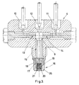
- Figure 3 is a view in cross-section of a part of a first embodiment of the device according to the invention for applying a method according to the invention.
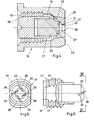
- Figure 4 is, at a larger scale, a cross-section of a mouthpiece of the device illustrated in Figure 3.
- Figure 5 is a side-view, with partial cross-section, of a particular component of the mouthpiece according to figure 4.
- Figure 6 is a view according to the line VI-VI of figure 5.
- Figure 7 is a longitudinal section according to the line VII-VII of figure 8 of a second embodiment of a mouthpiece according to the invention.
- Figure 8 is a front view according to the line VIII-VIII of figure 7.
- Figure 9 is, at a larger scale, a front view according to the line IX-IX of figure 10 of a particular component of the mouthpiece according to the figures 7 and 8.
- Figure 10 is a side view of the same component according to the line X-X of figure 9.
- Figure 11 is a back view according to the line XI-XI of figure 10 of the component.
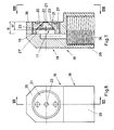
- Figure 12 is a front view of the mouthpiece according to a third embodiment of the device according to the invention.
- Figure 13 is a longitudinal section according to the line XIII-XIII of figure 12.
- Figure 14 is a similar cross-section, at a larger scale, of a particular component of the embodiment according to figures 12 and 13.
- Figure 15 is a back view according to the line XV-XV of figure 14.
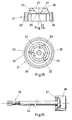
- Figure 16 represents partially longitudinal sections of the mouthpiece according to figures 12 and 13 before it is mounted on another part of a particular embodiment of the invention.
- Figure 17 is a front view according to line XVII-XVII of figure 18, of a further embodiment of a particular component according to figure 9.
- Figure 18 is a lateral view with a partial cross-section according to the line XVIII-XVIII of figure 19.
- Figure 19 is a back view, according to the line XIX-XIX of figure 18.
- Figure 20 is a longitudinal section according to the line XX-XX of figure 21 of a further embodiment of a mouthpiece according to the invention.
- Figure 21 is a front view according to the line XXI-XXI of figure 20.
- the invention relates to a method for forming a gellified polyurethane layer on a surface, more particularly on an adequate surface of a mould.
- An object of the invention is in particular the formation, in a mould, of an elastomer layer of polyurethane which is stable to light and which has a minimal thickness of 0.3 mm and preferably ranging between 0.5 and 2 mm, so that a print is obtained which serves as aesthetical recovering, in particular for orning the ashboard of automobiles.
- the elastomer layer is preferably formed according to the so-called "airless two-component-system in absence or substantially absence of solvent means".
- Figure 1 represents a schematic view of the applied method.
- the two components i.e. polyol and isocyanates
- a tank 1A, respectively 1B by means of gauge pumps 2A, respectively 2B, for consequently, in a second step, to be brought at an adequate temperature by means of a heat exchanger respectively 3A and 3B before to be mixed in a mixing head 4 on which a mouthpiece 16 is connected from which a beam of the thus formed reaction mixture is sprayed on a mould surface in order to form said elastomer layer.
- the reaction mixture is sprayed under the form of a film and/or of raindrops of which the largest part has a mean diameter (Medium Volume Diameter) according to the standards ASTM E 779-81 higher than 100 microns and preferably higher than 500 microns.
- the beam of liquid which is sprayed out of the mouthpiece comprises generally two parts 7 and 8 of which the physical aspect is substantially different. So the part 7, which is the closest to the mouthpiece, is formed by a film 7′ which extends according to the surface of a cone with a cross-section having the form of a circle or an oval, depending on the kind of the used mouthpiece, while in the part 8 that film is broken up into drops 8′.
- d a distance between the mouthpiece 16 and the surface on which the elastomer has to be formed, which distance lies between 0.5 cm and 30 cm and preferably between 15 and 20 cm.
- Figure 2 shows, in plane lines, a first advantageously case where the surface 25 to be covered by an elastomer layer 26 is at a distance d of the mouthpiece 16, which is larger than the height h1 of the part 7 of the diameter of the reaction mixture and, in broken lines, a second case wherein the surface 25′ is at a distance d′ which is smaller than that height h1.
- the layer 26 is formed by the drops 8′, while in the second case it is formed by the film 7′.
- the height h1 of that part 7 is, for a same mouthpiece, essentially determined in function of the viscosity of the reaction mixture of the angle ⁇ and of the throughput of the sprayed liquid.
- this mixture should be sprayed under the form of a film which extends starting from the mouthpiece 16 and according to a hollow possibly somewhat cambered cone of which the top angle ⁇ is comprised between 5° and 80° and preferably between 20° and 40°.
- the reaction mixture has to be distributed substantially under the form of drops over the surface to be covered, it has been established that the most favourable results can be obtained when the largest part of those drops 8′ shows a relatively large mean diameter, which is mostly comprised between 1000 and 5000 microns, and preferably between 500 and 3000 microns.
- the height h2 of this part 8, compared to that of the part 7, can be relatively important if the reaction mixture is sprayed with a relatively limited throughput on the surface to be covered.
- Figures 3 to 6 relate to a spray-gun, which according to the invention can be used for applying the method described above.
- the gun comprises essentially a mixing chamber 9 having an input for polyol 10, for isocyanate 11 and for rinsing means 12, which can be closed by means of a ball-valve.
- the injectors 13 and 14 for the polyol and the isocyanates are respectively provided between the inputs 10 and 11, on the one side, and the mixing chamber 9, on the other side. Those injectors issue forth in that chamber 9 according to opposite directions and thus enable the introduction with a relatively high speed of the polyol and the isocyanates in counter-current in that chamber.
- the figures 3 to 6 relates to a first embodiment of such a mouthpiece.
- That mouthpiece 16 comprises a central core 17 which is screwed in a cylindrically shaped hollow body 18, in such a manner that a ring-shaped admission chamber 19 is formed around that core 17.
- the core 17 only shows thus at its back-part an external screw thread 17′ which cooperates with the internal wall of the hollow body 18 and which is provided with a screw thread 18′.
- the core 17 shows an input piece having a truncated cone-shaped part 20 which penetrates in a funnel-shaped cavity 27 of the injector 21 provided with an injection aperture 22, which injector 21 is mounted on cone-shaped perforation in the head of the mouthpiece 16.
- the truncated cone-shaped part 20 is, as has been clearly shown on a large scale in figures 4, 5 and 6, provided at its wall with four grooves 23 allowing the injection apertures 22 to be connected to the ring-shaped chamber 19.
- the four grooves 23 generally show a depth and a thickness of 0.1 mm to 2 mm and preferably of 0.3 mm to 1 mm. They are further equally distributed over the truncated cone-shaped part 20 of the core 17 and are excentrical and oriented according to a screw-form in such a manner that the reaction mixture, originating from chamber 19, is introduced according to a screw or whirl movement in the funnel-shaped cavity 27 of the injector 21, as clearly seen from the relative direction of the arrows 28, shown in figures 4 to 6.
- the funnel-shaped cavity 27 is elongated by a cylindrically shaped channel 29 which issues forth in the injection aperture 22.
- the cylindrically shaped channel 29 shows a lenght from 0 to 3 mm and preferably between 0.1 and 0.6 mm. It has indeed been established, on a somewhat unforeseen manner, that the form of the reaction mixture beam which is formed at the output of the mouthpiece 16, is essentially determined by the length of the cylindricaly shaped channel 29 for a reaction mixture with a same viscosity. More particularly an adequate choice of that length permits to obtain at the output of the mouthpiece a beam which has the characteristics defined hereabove, more particularly as has been illustrated in figure 2.
- the cylindrically shaped channel be relatively short compared to the length of that part by the known mouthpieces, which are for example used for spraying paints having a viscosity beneath 20 centipoises. In some cases this may be totally inexistent. It has thus been established that, when the cylindrically shaped channel is relatively long, it is no longer possible to form a film of liquid at the output of the mouthpiece 16 which film of liquid extends according to the surface of a cone, as has been explained hereabove.
- the injection aperture 22 shows generally a diameter of 0.2 to 5 mm and preferably of 0.7 to 2 mm.
- the truncated cone part 20 of the core 17 even as the injector 21 are preferably manufactured in tungstene carbide, though other materials with enough hardness and resistance against use can also be used.
- the core 17 is directly mounted on a cylindrical extension piece 21′ of the injector 21 and there is spared in the cylindrical part 20′ of the core, which is backwards situated with respect to the funnel-shaped cavity 27, a sufficiently large diametrically extending groove 19 which forms said supply chamber. That supply chamber is then also in connection, at the one hand, with the grooves 23 provided in the truncated cone-shaped part 20 and, at the other hand, with the mixture chamber 9.
- the part 20 of the core 17 shows only two grooves 23 which extend diametrically opposite against each other. If required, more grooves can of course be provided. In the case of four grooves, for example, it is enough to provide in the part 20′ of the core 17 two grooves 19 which extend perpendicular to each other which connect these grooves 23 to each other.
- the figures 12 to 15 relate to a third embodiment of a mouthpiece 16 according to the invention.
- This embodiment distinguishes from the other essentially by the fact that there is no central core 17 present and that the grooves 23 are provided in the injector 21 in the border 30 of the funnel-shaped cavity 27 of the latter.
- the border 30 joints the flat inner face 31 of the hollow body 18 wherein said injector 21 is screwed.
- the latter further shows at its frontside a relatively high upstanding border 32 which is provided with an external screw thread 32′ serving to fix the injector 21 in the body 18.
- the injection aperture 22 is somewhat sunk in the body 18 and at the other side of that aperture 22 a protection zone 33 is formed for the liquid beam at the output of the injector.
- a tube-shaped element 34 which connects the mouthpiece to the mixing chamber 9, via the conduct 15.
- That element can for example be formed by a static mixer as has been shown in figure 16 and which is known on its own.
- the body 18 of the two latest embodiments is also essentially tube-shaped except perhaps for the head 35 thereof, which is flattened and forms the free end of the mouthpiece, and the extremity of the hollow body 18 which is situated at the opposite side of the head 35 is provided with a screw thread 36.
- the tube-shaped body shows a longitudinal perforation 39 which extends starting from the supply chamber 19 until the extremity of the body situated at the other end.
- the mouthpiece 16 can easily be screwed on the free end of that element 34, which is thus also provided with a screw thread.
- the axis of the cylindrical channel 29 with the injection aperture 22 is perpendicular on the one of the tube-shaped element 34. That latest shows at the extremity, situated at the other side of its free extremity, a collar 37 which is fixed on the mixer head 4, as has been illustrated in figure 3, by means of a shell-shaped bolt 38.
- FIG. 17 another particular embodiment of the core 17 is illustrated which could, for example, replace the core of the second embodiment of the mouthpiece according to the invention and which has been illustrated in figures 7 to 11.
- That core distinguishes from the one illustrated in figures 9 to 11 by the fact the supply chamber 19 is formed by a central sparing instead of a groove which extends diametrically in the back part 20′. That central sparing is connected, via cylindrically shaped perforations 40, with the four grooves 23, which are equally disposed over the truncated cone-shaped wall of the part 20 of the core 17 and which are oriented screw-formed with respect to the axis of that part 20. These perforations, which have been carefully realized, extend from the central chamber 19 to the grooves 23.
- FIGS. 20 and 21 show a further embodiment of a mouthpiece 16 according to the invention.
- This mouthpiece is distinguished from the previously presented one by the presence of means enabling to control the spray pattern independentaly of the throughput, more particularly the surface of the on its axis perpendicular cross-section of the sprayed cone of liquid, as schematically illustrated in figure 2.
- this is realized by air control, that is to say by means of a curtain of compressed air which is formed around the sprayed cone of liquid and which enables, by controlling the throughput of the compressed air, to apply a well determined lateral pressure on the face of the cone 7 (see figure 2) and to bend it towards inside.
- the small holes 41 are situated in an oblique surface at the inner side of a border 43 of said body which is upstanding with respect to the axis 42 and which has a communication with a ring-shaped chamber 44 which extends around the body 18 and on which a compressed air conduct 45 is connected.
- the pressure of the compressed air stream can be controlled, this compressed air stream being oblique oriented on the outher side of the cone wall 7, by means of the holes 41, according to which that cone wall can be bent towards the axis 42.
- the invention is again of interest for applications wherein there is sprayed in shallow small moulds and where the losses of spraying have to be minimized.
- the static mixer 34 has to be provided between the mixture chamber 9 and the mouthpiece 16, for example when the homogeneity of the mixture leaving the chamber 9 is unsufficient.
- mouthpiece 16 also several constructions of the mouthpiece 16 are possible and eventually other means than grooves 23 can be used in order to realize the screw or whirl movement of the liquid to be sprayed through the spray aperture 21.
Priority Applications (1)
| Application Number | Priority Date | Filing Date | Title |
|---|---|---|---|
| AT88201346T ATE81034T1 (de) | 1987-07-16 | 1988-06-29 | Verfahren und vorrichtung zur beschichtung einer oberflaeche mit einer polyurethanschicht. |
Applications Claiming Priority (2)
| Application Number | Priority Date | Filing Date | Title |
|---|---|---|---|
| BE8700792 | 1987-07-16 | ||
| BE8700792A BE1000767A7 (nl) | 1987-07-16 | 1987-07-16 | Werkwijze en inrichting voor het vormen van een laag polyurethaan op een oppervlak door spuiten. |
Publications (3)
| Publication Number | Publication Date |
|---|---|
| EP0303305A2 EP0303305A2 (en) | 1989-02-15 |
| EP0303305A3 EP0303305A3 (en) | 1990-01-31 |
| EP0303305B1 true EP0303305B1 (en) | 1992-09-30 |
Family
ID=3882770
Family Applications (1)
| Application Number | Title | Priority Date | Filing Date |
|---|---|---|---|
| EP88201346A Expired - Lifetime EP0303305B1 (en) | 1987-07-16 | 1988-06-29 | Method and device for forming,by spraying, a polyurethane layer on a surface |
Country Status (25)
| Country | Link |
|---|---|
| US (1) | US5071683A (fi) |
| EP (1) | EP0303305B1 (fi) |
| JP (1) | JP2610308B2 (fi) |
| KR (1) | KR960013920B1 (fi) |
| CN (1) | CN1024167C (fi) |
| AT (1) | ATE81034T1 (fi) |
| AU (1) | AU611450B2 (fi) |
| BE (1) | BE1000767A7 (fi) |
| BR (1) | BR8803578A (fi) |
| CA (1) | CA1302801C (fi) |
| DE (1) | DE3875029T2 (fi) |
| DK (1) | DK386488A (fi) |
| ES (1) | ES2034161T3 (fi) |
| FI (1) | FI95216C (fi) |
| GR (1) | GR3006184T3 (fi) |
| IE (1) | IE64847B1 (fi) |
| LV (1) | LV10591B (fi) |
| MD (1) | MD940205A (fi) |
| MX (1) | MX171507B (fi) |
| MY (1) | MY103312A (fi) |
| NO (1) | NO302511B1 (fi) |
| PH (1) | PH26983A (fi) |
| PL (1) | PL160684B1 (fi) |
| PT (1) | PT87999B (fi) |
| RU (1) | RU2040346C1 (fi) |
Cited By (16)
| Publication number | Priority date | Publication date | Assignee | Title |
|---|---|---|---|---|
| EP0386818A1 (en) * | 1989-03-03 | 1990-09-12 | Recticel | A method of making objects having an elastomeric outer wall and a synthetic foam core |
| EP0619989A2 (en) * | 1993-04-13 | 1994-10-19 | Roger William Dodd | Padded room and method of construction thereof |
| EP1177949A1 (en) * | 2000-08-01 | 2002-02-06 | Recticel | Method for manufacturing a trim part for the interior of an automobile vehicle or at least a skin therefor |
| US6432543B2 (en) | 1998-07-29 | 2002-08-13 | Basf Corporation | Decorative components having an elastomeric outer surface and methods of making such components |
| DE102005037972A1 (de) * | 2005-08-11 | 2007-02-22 | Krauss-Maffei Kunststofftechnik Gmbh | Düse für Sprühkopf |
| DE102007016785A1 (de) | 2007-04-05 | 2008-10-09 | Hennecke Gmbh | Verfahren zur Herstellung von Formteilen mit einer Schicht aus Polyurethan |
| EP2230068A2 (en) | 2006-05-30 | 2010-09-22 | Recticel Automobilsysteme GmbH | Method for producing a flexible elastomeric polyurethane skin |
| EP2269794A1 (en) | 2009-07-02 | 2011-01-05 | RECTICEL Automobilsysteme GmbH | Method of making an elastomeric skin and skin obtained by that method |
| WO2011107605A1 (en) | 2010-03-05 | 2011-09-09 | Recticel Automobilsysteme Gmbh | Method for producing a skin layer of a flexible, elastomeric, thermoset, phase-separated polyurethane material. |
| EP2679380A1 (en) | 2012-06-28 | 2014-01-01 | RECTICEL Automobilsysteme GmbH | Method for manufacturing a flexible skin having at least one insert adhered thereto. |
| EP3009248A1 (en) | 2014-10-13 | 2016-04-20 | RECTICEL Automobilsysteme GmbH | Method for producing an elastomeric skin having a grained surface |
| EP3015498A1 (en) | 2014-10-31 | 2016-05-04 | Recticel | Compressible sealing element and use thereof for filling the gap between a stock rail and a switch rail in a railway switch |
| DE102016106667A1 (de) | 2015-12-28 | 2017-06-29 | FORMTEC PUR-Verarbeitungs-GmbH | Formteil aus mehrlagigem PUR-Spray und Verfahren zur Herstellung |
| WO2018197691A1 (en) | 2017-04-28 | 2018-11-01 | Recticel Automobilsysteme Gmbh | Elastomeric composite polyurethane skins |
| WO2021144285A1 (en) | 2020-01-16 | 2021-07-22 | Ascorium Gmbh | Skin for a vehicle interior trim part comprising a light source |
| WO2021144286A1 (en) | 2020-01-16 | 2021-07-22 | Ascorium Gmbh | Skin for a vehicle interior trim part containing an operating element |
Families Citing this family (48)
| Publication number | Priority date | Publication date | Assignee | Title |
|---|---|---|---|---|
| BE1003015A6 (nl) * | 1989-03-20 | 1991-10-22 | Recticel | Spuitkop voor spuitpistool voor het vormen van een laag polyurethaan op een oppervlak. |
| US5340613A (en) * | 1993-03-12 | 1994-08-23 | Minnesota Mining And Manufacturing Company | Process for simultaneously coating multiple layers of thermoreversible organogels and coated articles produced thereby |
| US5762853A (en) * | 1996-04-01 | 1998-06-09 | Morton International, Inc. | Method of encapsulating a sensor into a panel body |
| US5885662A (en) * | 1997-01-31 | 1999-03-23 | Atoma International, Inc. | Decorative automotive interior trim articles with integral light stable polyurethane elastomer covering and process for making the same |
| KR20010006471A (ko) * | 1997-04-18 | 2001-01-26 | 콘 게리 엠 | 주조 일체형 광-안정성 덮개를 갖는 자동차 내부의 장식용 외장품 및 제조 공정 |
| BR9810131A (pt) | 1997-06-16 | 2000-08-08 | Magna Interior Systens Inc | Processo para fabricar uma estrutura semelhante a um painel, e, artigo |
| US6020387A (en) * | 1997-09-22 | 2000-02-01 | Caschem, Inc. | Low density polymers and methods of making and using same |
| US6544449B1 (en) | 1998-05-22 | 2003-04-08 | Magna Interior Systems Inc. | Process for making decorative automotive interior trim articles with integral in-mold coated polyurethane aromatic elastomer covering |
| CA2343177A1 (en) | 1998-09-14 | 2000-03-23 | Magna Interior Systems, Inc. | Trim articles with light stable covering containing invisible tear seam, and process of making the same |
| EP0995568A1 (en) | 1998-10-21 | 2000-04-26 | Recticel | Method for manufacturing a multilayered moulded synthetic part and thus obtained part |
| DE19854405B4 (de) | 1998-11-25 | 2016-05-04 | Basf Se | Kompakte Kaschierung auf der Basis von Polyisocyanat-Polyadditionsprodukten |
| US6352658B1 (en) | 1999-12-30 | 2002-03-05 | Basf Corporation | Method for producing decorative components having an outer elastomeric layer that is integral with an inner foam layer |
| MX336248B (es) * | 2001-12-03 | 2016-01-13 | Red Spot Paint & Varnish | Interiores de automotores y otros productos revestidos durante el moldeo y los metodos para manufacturar los mismos. |
| JPWO2004076072A1 (ja) * | 2003-02-25 | 2006-06-01 | 三井武田ケミカル株式会社 | スプレーノズルチップおよびそれを用いた熱硬化性樹脂の製造方法 |
| US20040201130A1 (en) * | 2003-04-09 | 2004-10-14 | Paul Kampe | Method of producing polyurethane surfaces |
| US20040222310A1 (en) * | 2003-05-07 | 2004-11-11 | Lear Corporation | Method of spray polyurethane application utilizing internally mixed components applied with a flat fan spray |
| US20040247887A1 (en) * | 2003-06-04 | 2004-12-09 | Lear Corporation | System and method for coloring a spray urethane skin for vehicle interior trim components and particles made thereby |
| AU2004251453A1 (en) | 2003-06-27 | 2005-01-06 | Recticel | Method for producing a moulded article comprising a sprayed polyurethane layer |
| GB0319643D0 (en) * | 2003-08-21 | 2003-09-24 | Oliver Twinsafe Valves Ltd | An isolation valve assembly |
| US20050133958A1 (en) * | 2003-12-22 | 2005-06-23 | Lear Corporation | System and method for coloring a spray urethane skin for vehicle interior trim components and skins made thereby |
| US7070120B2 (en) * | 2003-12-23 | 2006-07-04 | Lear Corporation | Rotating spray head for spray urethane |
| DK1577080T3 (da) | 2004-03-19 | 2007-03-12 | Recticel | Fremgangsmåde til fremstilling af en panelsamling med en pakning |
| US20050218556A1 (en) * | 2004-04-02 | 2005-10-06 | Lear Corporation | Method and apparatus for spray forming polyurethane skins with a hydraulic mixing head |
| US7021498B2 (en) | 2004-04-06 | 2006-04-04 | Advanced Controls And Engineering | Urethane spray gun assembly |
| US7670524B2 (en) * | 2004-05-24 | 2010-03-02 | International Automotive Components Group North America | Method of over-molding TPE components using zero gate |
| US20050274821A1 (en) * | 2004-06-11 | 2005-12-15 | Lear Corporation | Heated spray applicator |
| US20060063894A1 (en) * | 2004-09-21 | 2006-03-23 | Ivan Alferiev | Degradation resistant polyurethanes |
| US20060073322A1 (en) * | 2004-10-01 | 2006-04-06 | Lear Corporation | Low density spray polyurethane for automobile interior applications |
| US7694894B2 (en) * | 2005-04-19 | 2010-04-13 | Warren Environmental, Inc. | Method and system for preheating epoxy coatings for spray application |
| JP4768331B2 (ja) * | 2005-06-28 | 2011-09-07 | トリニティ工業株式会社 | 塗装機 |
| DE102005048554A1 (de) * | 2005-10-11 | 2007-04-12 | Bayerische Motoren Werke Ag | Verfahren zur Herstellung eines Schichtkörpers |
| DE102005051995A1 (de) * | 2005-10-31 | 2007-05-03 | Lear Corporation, Southfield | Spritzpolyurethan mit niedriger Dichte für Kraftfahrzeuginnenraumanwendungen |
| DE102005058292A1 (de) * | 2005-12-07 | 2007-06-14 | Hennecke Gmbh | Verfahren und Vorrichtung zur Herstellung von beschichteten Formteilen |
| US20070145641A1 (en) * | 2005-12-22 | 2007-06-28 | Lear Corporation | Interior vehicle trim panel having colored dual density composite spray elastomer skin and system and method for making the same |
| EP2076402A1 (en) * | 2006-08-31 | 2009-07-08 | Pilkington Italia S.p.A. | Method for encapsulating the edge of a glass sheet |
| US7708208B1 (en) * | 2006-10-02 | 2010-05-04 | Ingo Werner Scheer | Method and apparatus to disintegrate liquids having a tendency to solidify |
| SI2152432T1 (sl) * | 2007-06-04 | 2013-08-30 | Recticel Automobilsysteme Gmbh | Šoba za vrtinčasto razprševanje pod pritiskom strjevalnega sestavka in z njo povezan postopek in uporaba |
| KR100911225B1 (ko) * | 2007-09-12 | 2009-08-06 | 주식회사 헵스켐 | 분말 분사 장치 및 이를 이용하는 경질 폴리우레탄 폼의제조 방법 |
| FR2939336A1 (fr) * | 2008-12-04 | 2010-06-11 | Multispe France | Procede d'assemblage de produits chimiques et d'application par projection d'un revetement de protection et/ou d'isolation des rails et/ou installations ferroviaires contre les courants vagabonds |
| DE102009052654A1 (de) * | 2009-11-11 | 2011-05-12 | Dürr Systems GmbH | Vorrichtung und Verfahren zur Konservierung von Bauteilen |
| MX350215B (es) | 2012-01-20 | 2017-08-30 | Basf Se | Cuerpo compuesto y metodo para hacer el mismo. |
| ITTV20130117A1 (it) * | 2013-07-25 | 2015-01-26 | Stemma Srl | Metodo per la realizzazione di manufatti mediante spruzzatura di una miscela di materiali polimerici espansi. |
| JP6158071B2 (ja) * | 2013-12-26 | 2017-07-05 | 花王株式会社 | トリガー式混合液噴出容器 |
| EP3486077B1 (en) * | 2017-11-17 | 2023-12-20 | 3M Innovative Properties Company | Multicellular structure comprising interconnected cells |
| EP3632641A1 (en) | 2018-10-01 | 2020-04-08 | RECTICEL Automobilsysteme GmbH | Method for producing an elastomeric skin |
| CN112590222B (zh) * | 2020-11-27 | 2022-12-02 | 江苏神力医用制品有限公司 | 一种注射器的自动化制造设备 |
| GR20210100039A (el) * | 2021-01-21 | 2022-08-08 | Αναστασιος Θεοφιλου Ριζοπουλος | Μεθοδος εγχυσης πολυουρεθανης σε προμονωμενους σωληνες στα σημεια ενωσης με εξαρτηματα |
| CN116080095B (zh) * | 2023-01-30 | 2023-09-19 | 浙江久石工研建材科技有限公司 | 一种仿夯土柔性贴片石制作工艺 |
Family Cites Families (13)
| Publication number | Priority date | Publication date | Assignee | Title |
|---|---|---|---|---|
| GB907230A (en) * | 1958-01-06 | 1962-10-03 | Gen Tire & Rubber Co | Process for producing cellular polyurethane elastomers |
| US3130910A (en) * | 1962-05-21 | 1964-04-28 | Delavan Mfg Company | Hydraulic atomizing spray gun |
| US3462083A (en) * | 1966-12-19 | 1969-08-19 | Robertson Co H H | Mixing nozzle and dispersion method |
| US3717306A (en) * | 1971-03-10 | 1973-02-20 | Hushon R | Nozzle for spraying foaming materials |
| JPS5022841A (fi) * | 1973-06-29 | 1975-03-11 | ||
| IT1094411B (it) * | 1977-08-02 | 1985-08-02 | Werding Winfried J | Ugello spruzzatore,dispositivi comprendenti tale ugello e procedimento per la loro produzione |
| US4234445A (en) * | 1979-01-25 | 1980-11-18 | Uniroyal, Inc. | Polyurethane spray composition containing lactone viscosity modifier |
| CA1159356A (en) * | 1979-10-25 | 1983-12-27 | Kurt Skoog | Method and device for producing microdroplets of fluid |
| EP0028088B1 (en) * | 1979-10-25 | 1984-02-08 | Sumitomo Light Metal Industries Limited | Method, apparatus and spray nozzle for coating the inner surface of long tubes of small diameter |
| US4337281A (en) * | 1981-02-25 | 1982-06-29 | Nordson Corporation | Method for striping inside seams of cans |
| US4603813A (en) * | 1984-06-29 | 1986-08-05 | Insta-Foam Products, Inc. | Double back spray nozzle |
| US4543366A (en) * | 1984-09-10 | 1985-09-24 | Thermocell Development, Ltd. | Sprayable urethane resin composition and method |
| US4809909A (en) * | 1985-06-13 | 1989-03-07 | Glas-Craft, Inc. | Plural component application system |
-
1987
- 1987-07-16 BE BE8700792A patent/BE1000767A7/nl not_active IP Right Cessation
-
1988
- 1988-06-29 EP EP88201346A patent/EP0303305B1/en not_active Expired - Lifetime
- 1988-06-29 AT AT88201346T patent/ATE81034T1/de not_active IP Right Cessation
- 1988-06-29 ES ES198888201346T patent/ES2034161T3/es not_active Expired - Fee Related
- 1988-06-29 DE DE8888201346T patent/DE3875029T2/de not_active Expired - Lifetime
- 1988-06-29 AU AU18538/88A patent/AU611450B2/en not_active Expired
- 1988-07-06 MY MYPI88000748A patent/MY103312A/en unknown
- 1988-07-06 IE IE205288A patent/IE64847B1/xx not_active IP Right Cessation
- 1988-07-07 FI FI883246A patent/FI95216C/fi not_active IP Right Cessation
- 1988-07-08 US US07/216,602 patent/US5071683A/en not_active Expired - Lifetime
- 1988-07-11 DK DK386488A patent/DK386488A/da not_active Application Discontinuation
- 1988-07-14 CA CA000572093A patent/CA1302801C/en not_active Expired - Lifetime
- 1988-07-14 NO NO883144A patent/NO302511B1/no unknown
- 1988-07-15 MX MX012278A patent/MX171507B/es unknown
- 1988-07-15 BR BR8803578A patent/BR8803578A/pt not_active IP Right Cessation
- 1988-07-15 RU SU884356169A patent/RU2040346C1/ru active
- 1988-07-15 PT PT87999A patent/PT87999B/pt not_active IP Right Cessation
- 1988-07-15 JP JP63176874A patent/JP2610308B2/ja not_active Expired - Lifetime
- 1988-07-16 PL PL1988273759A patent/PL160684B1/pl unknown
- 1988-07-16 CN CN88104456A patent/CN1024167C/zh not_active Expired - Fee Related
- 1988-07-16 KR KR1019880008915A patent/KR960013920B1/ko not_active IP Right Cessation
- 1988-07-22 PH PH37212A patent/PH26983A/en unknown
-
1992
- 1992-11-05 GR GR920402505T patent/GR3006184T3/el unknown
-
1993
- 1993-03-10 LV LVP-93-176A patent/LV10591B/en unknown
-
1994
- 1994-07-14 MD MD94-0205A patent/MD940205A/ro unknown
Cited By (28)
| Publication number | Priority date | Publication date | Assignee | Title |
|---|---|---|---|---|
| EP0386818A1 (en) * | 1989-03-03 | 1990-09-12 | Recticel | A method of making objects having an elastomeric outer wall and a synthetic foam core |
| EP0619989A2 (en) * | 1993-04-13 | 1994-10-19 | Roger William Dodd | Padded room and method of construction thereof |
| US6649107B2 (en) | 1998-07-29 | 2003-11-18 | Basf Corporation | Decorative components having an elastomeric outer surface and methods of making such components |
| US6852403B2 (en) | 1998-07-29 | 2005-02-08 | Basf Corporation | Decorative components having an elastomeric outer surface and methods of making such components |
| US6432543B2 (en) | 1998-07-29 | 2002-08-13 | Basf Corporation | Decorative components having an elastomeric outer surface and methods of making such components |
| EP1970257A2 (en) | 2000-08-01 | 2008-09-17 | Recticel | Method for manufacturing a trim part for the interior of an automobile vehicle or at least a skin therefor |
| WO2002009977A1 (en) * | 2000-08-01 | 2002-02-07 | Recticel | Method for manufacturing an automotive trim part |
| EP2275307A1 (en) | 2000-08-01 | 2011-01-19 | Recticel Automobilsysteme GmbH | Method for manufacturing a trim part for the interior of an automobile vehicle or at least a skin therefor. |
| EP1177949A1 (en) * | 2000-08-01 | 2002-02-06 | Recticel | Method for manufacturing a trim part for the interior of an automobile vehicle or at least a skin therefor |
| DE102005037972A1 (de) * | 2005-08-11 | 2007-02-22 | Krauss-Maffei Kunststofftechnik Gmbh | Düse für Sprühkopf |
| EP2230068A2 (en) | 2006-05-30 | 2010-09-22 | Recticel Automobilsysteme GmbH | Method for producing a flexible elastomeric polyurethane skin |
| DE102007016785A1 (de) | 2007-04-05 | 2008-10-09 | Hennecke Gmbh | Verfahren zur Herstellung von Formteilen mit einer Schicht aus Polyurethan |
| CN102470571A (zh) * | 2009-07-02 | 2012-05-23 | 雷克蒂塞尔汽车配件有限公司 | 制造弹性表层的方法及由该方法获得的表层 |
| EP2269794A1 (en) | 2009-07-02 | 2011-01-05 | RECTICEL Automobilsysteme GmbH | Method of making an elastomeric skin and skin obtained by that method |
| WO2011000957A1 (en) | 2009-07-02 | 2011-01-06 | Recticel Automobilsysteme Gmbh | Method of making an elastomeric skin and skin obtained by that method |
| CN102470571B (zh) * | 2009-07-02 | 2014-10-15 | 雷克蒂塞尔汽车配件有限公司 | 制造弹性表层的方法及由该方法获得的表层 |
| WO2011107605A1 (en) | 2010-03-05 | 2011-09-09 | Recticel Automobilsysteme Gmbh | Method for producing a skin layer of a flexible, elastomeric, thermoset, phase-separated polyurethane material. |
| EP2365012A1 (en) | 2010-03-05 | 2011-09-14 | RECTICEL Automobilsysteme GmbH | Method for producing a skin layer of a flexible, elastomeric, thermoset, phase-separated polyurethane material |
| EP2679380A1 (en) | 2012-06-28 | 2014-01-01 | RECTICEL Automobilsysteme GmbH | Method for manufacturing a flexible skin having at least one insert adhered thereto. |
| WO2014001462A1 (en) | 2012-06-28 | 2014-01-03 | Recticel Automobilsysteme Gmbh | Method for manufacturing a flexible skin having at least one insert adhered thereto |
| EP3009248A1 (en) | 2014-10-13 | 2016-04-20 | RECTICEL Automobilsysteme GmbH | Method for producing an elastomeric skin having a grained surface |
| WO2016058983A1 (en) | 2014-10-13 | 2016-04-21 | Recticel Automobilsysteme Gmbh | Method for producing an elastomeric skin having a grained surface |
| EP3015498A1 (en) | 2014-10-31 | 2016-05-04 | Recticel | Compressible sealing element and use thereof for filling the gap between a stock rail and a switch rail in a railway switch |
| DE102016106667A1 (de) | 2015-12-28 | 2017-06-29 | FORMTEC PUR-Verarbeitungs-GmbH | Formteil aus mehrlagigem PUR-Spray und Verfahren zur Herstellung |
| DE102016106668A1 (de) | 2015-12-28 | 2017-06-29 | FORMTEC PUR-Verarbeitungs-GmbH | Formteil aus mehrlagigem PUR Spray und Verfahren zur Herstellung |
| WO2018197691A1 (en) | 2017-04-28 | 2018-11-01 | Recticel Automobilsysteme Gmbh | Elastomeric composite polyurethane skins |
| WO2021144285A1 (en) | 2020-01-16 | 2021-07-22 | Ascorium Gmbh | Skin for a vehicle interior trim part comprising a light source |
| WO2021144286A1 (en) | 2020-01-16 | 2021-07-22 | Ascorium Gmbh | Skin for a vehicle interior trim part containing an operating element |
Also Published As
Similar Documents
| Publication | Publication Date | Title |
|---|---|---|
| EP0303305B1 (en) | Method and device for forming,by spraying, a polyurethane layer on a surface | |
| EP0389014B1 (en) | A spray nozzle for spray gun for forming a polyurethane layer on a surface | |
| US8318259B2 (en) | Method for producing a moulded article comprising a sprayed polyurethane layer | |
| US4632314A (en) | Adhesive foam generating nozzle | |
| US5565241A (en) | Convergent end-effector | |
| KR100433299B1 (ko) | 열경화성플라스틱공급노즐및방법 | |
| JP4834861B2 (ja) | 流体混合機構 | |
| CA1262022A (en) | Method and apparatus for producing a foam from a molten thermoplastic material | |
| JPS6337095Y2 (fi) |
Legal Events
| Date | Code | Title | Description |
|---|---|---|---|
| PUAI | Public reference made under article 153(3) epc to a published international application that has entered the european phase |
Free format text: ORIGINAL CODE: 0009012 |
|
| AK | Designated contracting states |
Kind code of ref document: A2 Designated state(s): AT BE CH DE ES FR GB GR IT LI LU NL SE |
|
| PUAL | Search report despatched |
Free format text: ORIGINAL CODE: 0009013 |
|
| AK | Designated contracting states |
Kind code of ref document: A3 Designated state(s): AT BE CH DE ES FR GB GR IT LI LU NL SE |
|
| 17P | Request for examination filed |
Effective date: 19900301 |
|
| 17Q | First examination report despatched |
Effective date: 19910305 |
|
| GRAA | (expected) grant |
Free format text: ORIGINAL CODE: 0009210 |
|
| AK | Designated contracting states |
Kind code of ref document: B1 Designated state(s): AT BE CH DE ES FR GB GR IT LI LU NL SE |
|
| REF | Corresponds to: |
Ref document number: 81034 Country of ref document: AT Date of ref document: 19921015 Kind code of ref document: T |
|
| REF | Corresponds to: |
Ref document number: 3875029 Country of ref document: DE Date of ref document: 19921105 |
|
| ITF | It: translation for a ep patent filed |
Owner name: ING. ZINI MARANESI & C. |
|
| ET | Fr: translation filed | ||
| REG | Reference to a national code |
Ref country code: ES Ref legal event code: FG2A Ref document number: 2034161 Country of ref document: ES Kind code of ref document: T3 |
|
| REG | Reference to a national code |
Ref country code: GR Ref legal event code: FG4A Free format text: 3006184 |
|
| EPTA | Lu: last paid annual fee | ||
| PLBE | No opposition filed within time limit |
Free format text: ORIGINAL CODE: 0009261 |
|
| STAA | Information on the status of an ep patent application or granted ep patent |
Free format text: STATUS: NO OPPOSITION FILED WITHIN TIME LIMIT |
|
| 26N | No opposition filed | ||
| EAL | Se: european patent in force in sweden |
Ref document number: 88201346.9 |
|
| PGFP | Annual fee paid to national office [announced via postgrant information from national office to epo] |
Ref country code: GR Payment date: 19960423 Year of fee payment: 9 |
|
| PG25 | Lapsed in a contracting state [announced via postgrant information from national office to epo] |
Ref country code: GR Free format text: LAPSE BECAUSE OF NON-PAYMENT OF DUE FEES Effective date: 19970630 |
|
| PGFP | Annual fee paid to national office [announced via postgrant information from national office to epo] |
Ref country code: LU Payment date: 19980519 Year of fee payment: 11 |
|
| PG25 | Lapsed in a contracting state [announced via postgrant information from national office to epo] |
Ref country code: LU Free format text: LAPSE BECAUSE OF NON-PAYMENT OF DUE FEES Effective date: 19990629 |
|
| REG | Reference to a national code |
Ref country code: GB Ref legal event code: IF02 |
|
| PGFP | Annual fee paid to national office [announced via postgrant information from national office to epo] |
Ref country code: ES Payment date: 20070726 Year of fee payment: 20 |
|
| PGFP | Annual fee paid to national office [announced via postgrant information from national office to epo] |
Ref country code: DE Payment date: 20070731 Year of fee payment: 20 |
|
| PGFP | Annual fee paid to national office [announced via postgrant information from national office to epo] |
Ref country code: AT Payment date: 20070705 Year of fee payment: 20 Ref country code: CH Payment date: 20070730 Year of fee payment: 20 |
|
| PGFP | Annual fee paid to national office [announced via postgrant information from national office to epo] |
Ref country code: GB Payment date: 20070727 Year of fee payment: 20 |
|
| PGFP | Annual fee paid to national office [announced via postgrant information from national office to epo] |
Ref country code: BE Payment date: 20070816 Year of fee payment: 20 Ref country code: IT Payment date: 20070723 Year of fee payment: 20 Ref country code: NL Payment date: 20070724 Year of fee payment: 20 Ref country code: SE Payment date: 20070727 Year of fee payment: 20 |
|
| PGFP | Annual fee paid to national office [announced via postgrant information from national office to epo] |
Ref country code: FR Payment date: 20070702 Year of fee payment: 20 |
|
| BE20 | Be: patent expired |
Owner name: *RECTICEL Effective date: 20080629 |
|
| REG | Reference to a national code |
Ref country code: GB Ref legal event code: PE20 Expiry date: 20080628 |
|
| REG | Reference to a national code |
Ref country code: CH Ref legal event code: PL |
|
| EUG | Se: european patent has lapsed | ||
| NLV7 | Nl: ceased due to reaching the maximum lifetime of a patent |
Effective date: 20080629 |
|
| REG | Reference to a national code |
Ref country code: ES Ref legal event code: FD2A Effective date: 20080630 |
|
| REG | Reference to a national code |
Ref country code: GB Ref legal event code: 732E |
|
| PG25 | Lapsed in a contracting state [announced via postgrant information from national office to epo] |
Ref country code: ES Free format text: LAPSE BECAUSE OF EXPIRATION OF PROTECTION Effective date: 20080630 Ref country code: NL Free format text: LAPSE BECAUSE OF EXPIRATION OF PROTECTION Effective date: 20080629 |
|
| PG25 | Lapsed in a contracting state [announced via postgrant information from national office to epo] |
Ref country code: GB Free format text: LAPSE BECAUSE OF EXPIRATION OF PROTECTION Effective date: 20080628 |
|
| REG | Reference to a national code |
Ref country code: FR Ref legal event code: CA Ref country code: FR Ref legal event code: TP |
|
| BECA | Be: change of holder's address |
Owner name: RECTICEL AUTOMOBILSYSTEME G.M.B.H.ROLANDSECKER WEG Effective date: 20090129 Owner name: RECTICEL AUTOMOBILSYSTEME G.M.B.H.ROLANDSECKER WEG Effective date: 20090127 |