EP0303092A2 - Verfahren zur Messung von Widerständen, insbesondere der Widerstände von Teilnehmeranschlussleitungen eines digitalen Zeitmultiplex-Fernmeldenetzes - Google Patents
Verfahren zur Messung von Widerständen, insbesondere der Widerstände von Teilnehmeranschlussleitungen eines digitalen Zeitmultiplex-Fernmeldenetzes Download PDFInfo
- Publication number
- EP0303092A2 EP0303092A2 EP88111979A EP88111979A EP0303092A2 EP 0303092 A2 EP0303092 A2 EP 0303092A2 EP 88111979 A EP88111979 A EP 88111979A EP 88111979 A EP88111979 A EP 88111979A EP 0303092 A2 EP0303092 A2 EP 0303092A2
- Authority
- EP
- European Patent Office
- Prior art keywords
- measuring circuit
- measurement
- resistances
- value
- measuring
- Prior art date
- Legal status (The legal status is an assumption and is not a legal conclusion. Google has not performed a legal analysis and makes no representation as to the accuracy of the status listed.)
- Granted
Links
Images
Classifications
-
- H—ELECTRICITY
- H04—ELECTRIC COMMUNICATION TECHNIQUE
- H04M—TELEPHONIC COMMUNICATION
- H04M3/00—Automatic or semi-automatic exchanges
- H04M3/22—Arrangements for supervision, monitoring or testing
- H04M3/26—Arrangements for supervision, monitoring or testing with means for applying test signals or for measuring
- H04M3/28—Automatic routine testing ; Fault testing; Installation testing; Test methods, test equipment or test arrangements therefor
- H04M3/30—Automatic routine testing ; Fault testing; Installation testing; Test methods, test equipment or test arrangements therefor for subscriber's lines, for the local loop
- H04M3/302—Automatic routine testing ; Fault testing; Installation testing; Test methods, test equipment or test arrangements therefor for subscriber's lines, for the local loop using modulation techniques for copper pairs
- H04M3/303—Automatic routine testing ; Fault testing; Installation testing; Test methods, test equipment or test arrangements therefor for subscriber's lines, for the local loop using modulation techniques for copper pairs and using PCM multiplexers, e.g. pair gain systems
-
- G—PHYSICS
- G01—MEASURING; TESTING
- G01R—MEASURING ELECTRIC VARIABLES; MEASURING MAGNETIC VARIABLES
- G01R27/00—Arrangements for measuring resistance, reactance, impedance, or electric characteristics derived therefrom
- G01R27/02—Measuring real or complex resistance, reactance, impedance, or other two-pole characteristics derived therefrom, e.g. time constant
Definitions
- the invention relates to a method for measuring resistances, in particular the resistances of subscriber lines of a digital time-division multiplex telecommunications network using a measuring circuit and a signal processor which controls the measuring circuit and determines the corresponding resistance values from the voltage values supplied by the measuring circuit as the measurement result.
- the object of the invention is to develop a method for measuring resistances of the type mentioned in such a way that the aforementioned problems of balancing and the influence of temperature change and aging of the measuring circuit components can be dealt with in a more cost-effective manner than before.
- This object is achieved with a method of the type mentioned at the outset, which is characterized in that, before each actual resistance measurement, a measurement is carried out with an idle and a measurement is carried out with a short-circuited measuring circuit input, that an evaluation factor is formed from the difference between the voltages supplied by the measuring circuit and the difference between the corresponding arithmetic voltage values by forming the quotient, and that the difference value from that in the actual resistance measurement and from that mentioned with a short-circuited measuring circuit input voltage value supplied by the measuring circuit is weighted with the evaluation factor and then converted into the resistance value of the measured resistance.
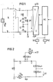
- the circuit arrangement shown in FIG. 1 for carrying out the method according to the invention is related to the measurement of the resistance of a subscriber line TL with the wires a and b together with the connected subscriber terminal TLN, which are shown on the left side of the figure.
- the actual measuring circuit of the arrangement shown consists of the series connection of a resistor R1 and two voltage sources U1 and U2, each of which supplies a voltage of 15 V.
- the wires a and b of the subscriber line are connected to the inputs E1 and E2 of this measuring circuit.
- the voltage drop across the resistor R1 is taken as the output voltage of the measuring circuit, the connection point of the voltage sources U1 and U2 serving as a reference point. It is reduced by means of a voltage divider consisting of the resistors R2 and R3, which is connected with its one connection to the connection E1 of the measuring circuit and with its other connection to the reference point, to a value which corresponds to the working range of a downstream analog-digital converter A. / D corresponds.
- the input (+) of the analog-digital converter A / D is connected to the dividing point of the voltage divider, the input (-) to the mentioned reference point.
- the choice of the connection point of the voltage sources U1 and U2 as the reference point ensures that the entire working range of the analog-digital converter A / D can be used.
- the analog-to-digital converter A / D is followed by a digital signal processor in the form of a microprocessor MC, which processes the measured values coming from the measuring circuit and controls the measuring circuit by influencing relays Re1 and Re2.
- the measuring circuit input E1 can be connected to the a wire of the subscriber line TL via the changeover contact 1 of the relay Re1. In its other switching position, it serves to short-circuit the measuring circuit on the input side via the connections E1 and E2 together with the closed contact 2 of the relay Re2.
- a measurement is carried out with the measuring circuit idling, for which purpose the control unit input 1 disconnects the a wire from the measuring circuit input E1 on the basis of a control command from the signal processor to the relay Re1.
- a measurement is also carried out when the measuring circuit input is short-circuited, for which purpose contacts 1 and 2 are brought into the other switching position than shown by corresponding control commands to both relays Re1 and Re2.
- the digital signal pro Processor MC supplied, which forms the difference UM -UM0.
- This difference value is the zero-point corrected value of the measuring voltage when the measuring circuit input is idling.
- the digital signal processor now also forms an evaluation factor, which is the quotient of the calculated zero-corrected voltage value UM with the measuring circuit input idling and the aforementioned measured value of this differential voltage.
- the actual measurement of the resistance of the subscriber line TL with the subscriber terminal TLN switched on now begins, for which purpose the contacts 1 and 2 are brought into the position shown.
- the voltage value UM occurring at the output of the measuring circuit is stored after an analog-to-digital conversion, and the signal processor MC then forms the difference value of this voltage value and the voltage value obtained in the course of step 1 with the measuring circuit input short-circuited. This difference value is then multiplied by the evaluation factor.
Landscapes
- Physics & Mathematics (AREA)
- General Physics & Mathematics (AREA)
- Engineering & Computer Science (AREA)
- Signal Processing (AREA)
- Monitoring And Testing Of Exchanges (AREA)
- Measurement Of Resistance Or Impedance (AREA)
- Heat Treatment Of Steel (AREA)
- Heat Treatment Of Sheet Steel (AREA)
- Medicines Containing Antibodies Or Antigens For Use As Internal Diagnostic Agents (AREA)
Abstract
Description
- Die Erfindung betrifft ein Verfahren zur Messung von Widerständen, insbesondere der Widerstände von Teilnehmeranschlußleitungen eines digitalen Zeitmultiplex-Fernmeldenetzes unter Verwendung eines Meßkreises und eines Signalprozessors, der den Meßkreis steuert und aus vom Meßkreis als Meßergebnis gelieferten Spannungswerten die entsprechenden Widerstandswerte ermittelt.
- Im Zuge eines derartigen Verfahrens ist es erforderlich, den Meßkreis zumindest bei seiner Installation abzugleichen und zwar für einen Nullwert und für den Endwert. Solche Abgleiche sind jeweils zu wiederholen, wenn eine Prüfeinrichtung, deren Bestandteil der Meßkreis ist, einer Wartung unterzogen worden ist. Bisher wurden solche Abgleiche manuell durch Einstellung von Potentiometern vorgenommen. Um dem Temperaturgang und der Alterung von Bauteilen des Meßkreises zu begegnen, wurden bisher einerseits hochwertige Bauteile eingesetzt, andererseits zusätzliche Bauteile zur Durchführung von Kompensationsmaßnahen verwendet.
- Die Aufgabe der Erfindung besteht darin, ein Verfahren zur Messung von Widerständen der eingangs genannten Art dahingehend auszugestalten, daß die vorerwähnten Probleme des Abgleichs und des Einflusses von Temperaturgang und Alterung der Meßkreisbauteile auf günstigere Art und Weise bewältigt werden können als bisher.
- Diese Aufgabe wird mit einem Verfahren der eingangs genannten Art gelöst, das dadurch gekennzeichnet ist, daß vor jeder eigentlichen Widerstandsmessung eine Messung bei leerlaufendem und eine Messung bei kurzgeschlossenem Meßkreiseingang vorgenommen wird, daß aus der Differenz der dabei vom Meßkreis gelieferten Spannungen und der Differenz der entsprechenden rechnerischen Spannungswerte durch Quotientenbildung ein Bewertungsfaktor gebildet wird, und daß der Differenzwert aus dem bei der eigentlichen Widerstandsmessung und aus dem genannten bei kurzgeschlossenem Meßkreiseingang vom Meßkreis gelieferten Spannungswert mit dem Bewertunsfaktor gewichtet und danach in den Widerstandswert des gemessenen Widerstandes umgewandelt wird.
- Aufgrund der erfindungsgemäßen Maßnahmen erübrigen sich manuelle Abgleiche, stattdessen werden zu Beginn jeder eigentlichen Widerstandsmessung zwei zusätzliche Messungen vorgenommen, deren Ergebnisse zur Bildung eines Bewertungsfaktors herangezogen werden. Die Wichtung der bei der eigentlichen Widerstandsmessung vom Meßkreis gelieferten Spannung mit diesem Wertungsfaktor ersetzt jedoch nicht nur einen Abgleich des Meßkreises, sie hat vielmehr auch zur Folge, daß der Meßwert unabhängig von Temperaturgang und Alterung der Bauteile des Meßkreises ist.
- Nachstehend wird die Erfindung anhand eines Ausführungsbeispiels unter Bezugnahme auf eine Zeichnung näher erläutert.
- In der Zeichnung zeigen:
- FIG 1 das Schaltbild einer Anordnung zur Durchführung des erfindungsgemäßen Verfahrens,
- FIG 2 ein Ersatzschaltbild des Meßkreises der Anordnung gemäß FIG 1.
- Die in FIG 1 dargestellte Schaltungsanordnung zur Durchführung des erfindungsgemäßen Verfahrens steht im Zusammenhang mit der Messung des Widerstandes einer Teilnehmeranschlußleitung TL mit den Adern a und b samt angeschlossenem Teilnehmerendgerät TLN, die auf der linken Seite der Figur dargestellt sind.
- Der eigentliche Meßkreis der dargestellten Anordnung besteht aus der Reihenschaltung eines Widerstandes R1 und zwei Spannungsquellen U1 und U2, die jeweils eine Spannung von 15 V liefern. Die Adern a und b der Teilnehmeranschlußleitung sind an die Eingänge E1 und E2 dieses Meßkreises angeschlossen.
- Die über dem Widerstand R1 abfallende Spannung wird als Ausgangsspannung des Meßkreises abgenommen, wobei der Verbindungspunkt der Spannungsquellen U1 und U2 als Bezugspunkt dient. Sie wird mittels eines aus den Widerständen R2 und R3 bestehenden Spannungsteilers, der mit seinem einen Anschluß an den Anschluß E1 des Meßkreises und mit seinem anderen Anschluß an den Bezugspunkt angeschlossen ist, auf einen Wert reduziert, der dem Arbeitsbereich eines nachgeschalteten Analog-Digital Wandlers A/D entspricht. Der Eingang (+) des Analog-Digital-Wandlers A/D ist an den Teilerpunkt des Spannungsteilers angeschlossen, der Eingang (-) an den erwähnten Bezugspunkt. Aufgrund der Wahl des Verbindungspunktes der Spannungsquellen U1 und U2 als Bezugspunkt wird erreicht, daß der gesamte Arbeitsbereich des Analog-Digital-Wandlers A/D ausgenutzt werden kann.
- Dem Analog-Digital-Wandler A/D ist ein digitaler Signalprozessor Form eines Mikroprozessors MC nachgeschaltet, der die vom Meßkreis kommenden Meßwerte verarbeitet und durch Beeinflussung von Relais Re1 und Re2 den Meßkreis steuert.
- Über den Umschaltekontakt 1 des Relais Re1 ist der Meßkreiseingang E1 mit der a-Ader der Teilnehmeranschlußleitung TL verbindbar. Er dient in seiner anderen Schaltstellung dazu, zusammen mit dem geschlossenen Kontakt 2 des Relais Re2 den Meßkreis eingangsseitig über den Anschlüssen E1 und E2 kurzzuschließen.
- Die FIG 2 zeigt ein Ersatzschaltbild des beschriebenen Meßkreises zusammen mit dem erwähnten Spannungsteiler R2/R3 und dem zu messenden Widerstand Rx der Teilnehmeranschlußleitung TL mit angeschlossenem Teilnehmerendgerät TLN. Anhand dieses Schaltbildes werden die Zusammenhänge zwischen der über dem Spannungsteilerwiderstand R3 abgegriffenen und dem Analog-Digital-Wandler A/D zugeführten Meßspannung UB und dem zu messenden Widerstand Rx offensichtlich. Es gelten demnach:
- 1. -U1+U2+I1·R1+I3·Rx = 0
- 2. -U1+I1·R1+I2(R2+R3) = 0
- 3. I2 = I1-I3
- 4. UM = I2·R3
- Bei einer realisierten Ausführungsform gilt: R1 = 150 kOhm, R2 = 1304 kOhm, R3 = 205 kOhm, U1 und U2 = 15 V. Es ergibt sich daraus folgende Übertragungsfunktion:

- Nachstehend wird auf die Durchführung des erfindungsgemäßen Verfahrens unter Verwendung der in FIG 1 dargestellten Anordnung näher eingegangen.
- Erfindungsgemäß wird vor jeder eigentlichen Widerstandsmessung eine Messung bei leerlaufendem Meßkreis vorgenommen, wozu aufgrund eines Steuerbefehls des Signalprozessors an das Relais Re1 mittels des Kontaktes 1 die a-Ader vom Meßkreiseingang E1 abgetrennt wird. Es wird ferner eine Messung bei kurzgeschlossenem Meßkreiseingang vorgenommen, wozu durch entsprechende Steuerbefehle an beide Relais Re1 und Re2 die Kontakte 1 und 2 in die jeweils andere als die dargestellte Schaltstellung gebracht werden. Aus den dabei jeweils vom Meßkreis gelieferten Meßspannungen UM werden nach einer Analog-Digital-Wandlung durch den Analog-Digital-Wandler A/D dem digitalen Signalpro zessor MC zugeführt, der daraus die Differenz UM -UM0 bildet. Dieser Differenzwert ist der nullpunktkorrigierte Wert der Meßspannung bei Leerlauf des Meßkreiseingangs. Unter Anwendung der obengenannten Gleichung 5 ergibt sich rein rechnerisch für diesen Wert der Zusammenhang:

- Der Digitalsignalprozessor bildet nun außerdem einen Bewertungsfaktor, der der Quotient aus dem rechnerischen Nullpunkt korrigierten Spannungswert UM bei leerlaufendem Meßkreiseingang und dem vorgenannten gemessenen Wert dieser Differenzspannung ist.
- Es beginnt nunmehr die eigentliche Messung des Widerstandes der Teilnehmeranschlußleitung TL mit angeschaltetem Teilnehmerendgerät TLN, wozu die Kontakte 1 und 2 in die dargestellte Stellung gebracht werden. Der dabei am Ausgang des Meßkreises auftretende Spannungswert UM wird nach einer Analog-Digital Wandlung gespeichert, daraufhin wird durch den Signalprozessor MC der Differenzwert dieses Spannungswertes und das im Zuge des Schrittes 1 erhaltenen Spannungswertes bei kurzgeschlossenem Meßkreiseingang gebildet. Dieser Diffierenzwert wird daraufhin mit dem Bewertungsfaktor multipliziert.
- Schließlich wird der solcherart bewertete Spannungswert entsprechend dem durch die Gleichung 5 gegebenen Zusammenhang in einen Widerstandswert umgerechnet und ausgegeben. Dieser Widerstandswert wird ausgegeben und angezeigt, womit, die Meßprozedur abgeschlossen ist.

Claims (2)
Priority Applications (1)
| Application Number | Priority Date | Filing Date | Title |
|---|---|---|---|
| AT88111979T ATE98779T1 (de) | 1987-08-12 | 1988-07-25 | Verfahren zur messung von widerstaenden, insbesondere der widerstaende von teilnehmeranschlussleitungen eines digitalen zeitmultiplex-fernmeldenetzes. |
Applications Claiming Priority (2)
| Application Number | Priority Date | Filing Date | Title |
|---|---|---|---|
| DE3726882 | 1987-08-12 | ||
| DE3726882 | 1987-08-12 |
Publications (3)
| Publication Number | Publication Date |
|---|---|
| EP0303092A2 true EP0303092A2 (de) | 1989-02-15 |
| EP0303092A3 EP0303092A3 (en) | 1990-10-31 |
| EP0303092B1 EP0303092B1 (de) | 1993-12-15 |
Family
ID=6333605
Family Applications (1)
| Application Number | Title | Priority Date | Filing Date |
|---|---|---|---|
| EP88111979A Expired - Lifetime EP0303092B1 (de) | 1987-08-12 | 1988-07-25 | Verfahren zur Messung von Widerständen, insbesondere der Widerstände von Teilnehmeranschlussleitungen eines digitalen Zeitmultiplex-Fernmeldenetzes |
Country Status (5)
| Country | Link |
|---|---|
| US (1) | US4882742A (de) |
| EP (1) | EP0303092B1 (de) |
| AT (1) | ATE98779T1 (de) |
| DE (1) | DE3886299D1 (de) |
| FI (1) | FI883733L (de) |
Families Citing this family (4)
| Publication number | Priority date | Publication date | Assignee | Title |
|---|---|---|---|---|
| US5404388A (en) * | 1993-03-03 | 1995-04-04 | Northern Telecom Limited | Digital measurement of amplitude and phase of a sinusoidal signal and detection of load coil based on said measurement |
| US5606592A (en) * | 1993-06-16 | 1997-02-25 | Industrial Technology, Inc. | Method and apparatus for analyzing resistive faults on telephones cables |
| CA2295134A1 (en) * | 1998-01-15 | 1999-07-22 | Amethyst Technologies, Inc. | Improved pulsed electromagnetic energy treatment apparatus and method |
| CN109856456B (zh) * | 2018-12-07 | 2021-06-22 | 维沃移动通信有限公司 | 一种测量阻抗的方法、电子设备、电源适配器和系统 |
Family Cites Families (3)
| Publication number | Priority date | Publication date | Assignee | Title |
|---|---|---|---|---|
| US4337517A (en) * | 1976-09-16 | 1982-06-29 | Systron Donner Corporation | Method of automatically calibrating a microprocessor controlled digital multimeter |
| US4335349A (en) * | 1980-06-05 | 1982-06-15 | John Fluke Mfg. Co., Inc. | Simulated ohms generation method and apparatus for calibrating resistance type measuring instruments |
| AR240603A1 (es) * | 1985-04-30 | 1990-05-31 | Siemens Ag | Disposicion de circuito de prueba de lineas de conexion de abonados de disposisiones de enlace telefonico, para determinar tensiones analogicas producidas en dichas lineas de conexion de abonado |
-
1988
- 1988-07-25 EP EP88111979A patent/EP0303092B1/de not_active Expired - Lifetime
- 1988-07-25 AT AT88111979T patent/ATE98779T1/de active
- 1988-07-25 DE DE88111979T patent/DE3886299D1/de not_active Expired - Fee Related
- 1988-08-08 US US07/229,575 patent/US4882742A/en not_active Expired - Fee Related
- 1988-08-11 FI FI883733A patent/FI883733L/fi not_active IP Right Cessation
Also Published As
| Publication number | Publication date |
|---|---|
| EP0303092B1 (de) | 1993-12-15 |
| DE3886299D1 (de) | 1994-01-27 |
| FI883733A7 (fi) | 1989-02-13 |
| ATE98779T1 (de) | 1994-01-15 |
| US4882742A (en) | 1989-11-21 |
| EP0303092A3 (en) | 1990-10-31 |
| FI883733A0 (fi) | 1988-08-11 |
| FI883733L (fi) | 1989-02-13 |
Similar Documents
| Publication | Publication Date | Title |
|---|---|---|
| DE2808737C2 (de) | Schnittstelleneinrichtung, insbesondere Teilnehmerschaltung für Fernsprechanlagen | |
| DE4331796A1 (de) | Multimeter mit automatischer Meßfunktionseinstellung | |
| DE3382614T2 (de) | Kondensator-ueberwachungsschaltung. | |
| EP0303092B1 (de) | Verfahren zur Messung von Widerständen, insbesondere der Widerstände von Teilnehmeranschlussleitungen eines digitalen Zeitmultiplex-Fernmeldenetzes | |
| DE69225046T2 (de) | Gerät zur Messung des internen Widerstandes von Batterien, besonders in Motorfahrzeugen | |
| DE3634052C2 (de) | ||
| DE3101994C2 (de) | Verfahren zur Messung eines elektrischen Widerstands und Einrichtung zur Durchführung des Verfahrens | |
| DE2850929C2 (de) | Schaltungsanordnung zur Unterdrückung von Störspannungseinflüssen bei der Bewertung des Signalzustandes auf Übertragungsleitungen, insbesondere auf Teilnehmeranschlußleitungen in Fernsprechanlagen | |
| DE69002601T2 (de) | Vorrichtung zum Messen eines Parameters. | |
| EP0200038B1 (de) | Verfahren und Anordnung zum Ermitteln von an Teilnehmeranschlussleitungen eines digitalen Fernsprechvermittlungssystems auftretenden Werten analoger Spannungen | |
| EP0181469B1 (de) | Einrichtung zur optimalen Anpassung einer Gabelschaltung an eine Fernmeldeleitung. | |
| EP0580947A2 (de) | Verfahren zum Ermitteln einer elektrischen Kenngrösse | |
| EP0217131B1 (de) | Verfahren zur von der Leitungslänge von Teilnehmeranschlussleitungen eines Fernmeldevermittlungssystems unabhängigen Ermittlung der zeitlichen Kenngrössen von Wahlimpulsen | |
| DE2903340A1 (de) | Roentgendiagnostikgenerator mit mitteln zur gewinnung eines der roentgenroehrenspannung entsprechenden signals | |
| DE3634053A1 (de) | Verfahren und schaltungsanordnung zur messung der widerstandswerte zweier in reihe geschalteter sensorwiderstaende | |
| DE3215670C2 (de) | ||
| DE2949467C2 (de) | Verfahren zur Messung von Widerständen, Widerstandsdifferenzen und zum Fehlerorten | |
| DE3885782T2 (de) | Vorrichtung und Verfahren für die Ermittlung der Kenngrössen von Bauelementen in einer Ersatzschaltung mit drei Anschlüssen. | |
| EP0199979B1 (de) | Messverfahren zur Bestimmung des Schleifen- oder Innenwiderstandes eines Wechselstromnetzes und Vorrichtung zur Anwendung des Verfahrens | |
| DE2250336C3 (de) | Verfahren zum Feststellen der Länge einer Ader eines Kabels direkt im Längenmaß durch elektrische Brückenmessung, wenn Aderdurchmesser und Adertemperatur bekannt sind | |
| DE2357195C3 (de) | Verfahren zur Prüfung des Teilungsverhältnisses eines Hochspannungsteilers und Anordnung zur Durchführung des Verfahrens | |
| DE486006C (de) | Eichleitung fuer Nebensprechmessungen | |
| DE706753C (de) | Einrichtung zum Messen der Kapazitaet und des Verlustwinkels von kondensatoraehnlichen Objekten mittels eines komplexen Kompensators in einer Brueckenschaltung | |
| DE858575C (de) | Messverfahren zur Berichtigung der Ergebnisse von Fehlermessungen bei alladrigen Kabelnebenschluessen | |
| DE2619904B1 (de) | Schaltungsanordnung zum messen des durchgangswiderstandes |
Legal Events
| Date | Code | Title | Description |
|---|---|---|---|
| PUAI | Public reference made under article 153(3) epc to a published international application that has entered the european phase |
Free format text: ORIGINAL CODE: 0009012 |
|
| AK | Designated contracting states |
Kind code of ref document: A2 Designated state(s): AT BE CH DE FR GB IT LI NL SE |
|
| PUAL | Search report despatched |
Free format text: ORIGINAL CODE: 0009013 |
|
| AK | Designated contracting states |
Kind code of ref document: A3 Designated state(s): AT BE CH DE FR GB IT LI NL SE |
|
| 17P | Request for examination filed |
Effective date: 19901126 |
|
| 17Q | First examination report despatched |
Effective date: 19920807 |
|
| GRAA | (expected) grant |
Free format text: ORIGINAL CODE: 0009210 |
|
| AK | Designated contracting states |
Kind code of ref document: B1 Designated state(s): AT BE CH DE FR GB IT LI NL SE |
|
| REF | Corresponds to: |
Ref document number: 98779 Country of ref document: AT Date of ref document: 19940115 Kind code of ref document: T |
|
| REF | Corresponds to: |
Ref document number: 3886299 Country of ref document: DE Date of ref document: 19940127 |
|
| ITF | It: translation for a ep patent filed | ||
| GBT | Gb: translation of ep patent filed (gb section 77(6)(a)/1977) |
Effective date: 19940218 |
|
| ET | Fr: translation filed | ||
| PGFP | Annual fee paid to national office [announced via postgrant information from national office to epo] |
Ref country code: GB Payment date: 19940616 Year of fee payment: 7 |
|
| PGFP | Annual fee paid to national office [announced via postgrant information from national office to epo] |
Ref country code: AT Payment date: 19940622 Year of fee payment: 7 |
|
| PGFP | Annual fee paid to national office [announced via postgrant information from national office to epo] |
Ref country code: BE Payment date: 19940714 Year of fee payment: 7 |
|
| PGFP | Annual fee paid to national office [announced via postgrant information from national office to epo] |
Ref country code: FR Payment date: 19940725 Year of fee payment: 7 |
|
| PGFP | Annual fee paid to national office [announced via postgrant information from national office to epo] |
Ref country code: SE Payment date: 19940731 Year of fee payment: 7 Ref country code: NL Payment date: 19940731 Year of fee payment: 7 |
|
| PGFP | Annual fee paid to national office [announced via postgrant information from national office to epo] |
Ref country code: DE Payment date: 19940915 Year of fee payment: 7 |
|
| PGFP | Annual fee paid to national office [announced via postgrant information from national office to epo] |
Ref country code: CH Payment date: 19941017 Year of fee payment: 7 |
|
| PLBE | No opposition filed within time limit |
Free format text: ORIGINAL CODE: 0009261 |
|
| STAA | Information on the status of an ep patent application or granted ep patent |
Free format text: STATUS: NO OPPOSITION FILED WITHIN TIME LIMIT |
|
| 26N | No opposition filed | ||
| EAL | Se: european patent in force in sweden |
Ref document number: 88111979.6 |
|
| PG25 | Lapsed in a contracting state [announced via postgrant information from national office to epo] |
Ref country code: GB Effective date: 19950725 Ref country code: AT Effective date: 19950725 |
|
| PG25 | Lapsed in a contracting state [announced via postgrant information from national office to epo] |
Ref country code: SE Effective date: 19950726 |
|
| PG25 | Lapsed in a contracting state [announced via postgrant information from national office to epo] |
Ref country code: LI Effective date: 19950731 Ref country code: CH Effective date: 19950731 Ref country code: BE Effective date: 19950731 |
|
| BERE | Be: lapsed |
Owner name: SIEMENS A.G. Effective date: 19950731 |
|
| PG25 | Lapsed in a contracting state [announced via postgrant information from national office to epo] |
Ref country code: NL Effective date: 19960201 |
|
| REG | Reference to a national code |
Ref country code: CH Ref legal event code: PL |
|
| GBPC | Gb: european patent ceased through non-payment of renewal fee |
Effective date: 19950725 |
|
| NLV4 | Nl: lapsed or anulled due to non-payment of the annual fee |
Effective date: 19960201 |
|
| PG25 | Lapsed in a contracting state [announced via postgrant information from national office to epo] |
Ref country code: DE Effective date: 19960402 |
|
| EUG | Se: european patent has lapsed |
Ref document number: 88111979.6 |
|
| PG25 | Lapsed in a contracting state [announced via postgrant information from national office to epo] |
Ref country code: FR Effective date: 19960430 |
|
| REG | Reference to a national code |
Ref country code: FR Ref legal event code: ST |
|
| REG | Reference to a national code |
Ref country code: FR Ref legal event code: ST |
|
| REG | Reference to a national code |
Ref country code: FR Ref legal event code: ST |
|
| PG25 | Lapsed in a contracting state [announced via postgrant information from national office to epo] |
Ref country code: IT Free format text: LAPSE BECAUSE OF NON-PAYMENT OF DUE FEES;WARNING: LAPSES OF ITALIAN PATENTS WITH EFFECTIVE DATE BEFORE 2007 MAY HAVE OCCURRED AT ANY TIME BEFORE 2007. THE CORRECT EFFECTIVE DATE MAY BE DIFFERENT FROM THE ONE RECORDED. Effective date: 20050725 |