EP0303073A2 - Lastabhängige Bremskraftregeleinrichtung - Google Patents
Lastabhängige Bremskraftregeleinrichtung Download PDFInfo
- Publication number
- EP0303073A2 EP0303073A2 EP19880111646 EP88111646A EP0303073A2 EP 0303073 A2 EP0303073 A2 EP 0303073A2 EP 19880111646 EP19880111646 EP 19880111646 EP 88111646 A EP88111646 A EP 88111646A EP 0303073 A2 EP0303073 A2 EP 0303073A2
- Authority
- EP
- European Patent Office
- Prior art keywords
- shaft
- potentiometer
- leaf spring
- scanning
- control device
- Prior art date
- Legal status (The legal status is an assumption and is not a legal conclusion. Google has not performed a legal analysis and makes no representation as to the accuracy of the status listed.)
- Granted
Links
- 230000001419 dependent effect Effects 0.000 title claims abstract description 6
- 238000009434 installation Methods 0.000 title 1
- 230000001105 regulatory effect Effects 0.000 title 1
- 230000008878 coupling Effects 0.000 claims description 7
- 238000010168 coupling process Methods 0.000 claims description 7
- 238000005859 coupling reaction Methods 0.000 claims description 7
- 230000005540 biological transmission Effects 0.000 description 2
- 230000001627 detrimental effect Effects 0.000 description 1
- 238000010586 diagram Methods 0.000 description 1
- 230000036316 preload Effects 0.000 description 1
Images
Classifications
-
- B—PERFORMING OPERATIONS; TRANSPORTING
- B60—VEHICLES IN GENERAL
- B60T—VEHICLE BRAKE CONTROL SYSTEMS OR PARTS THEREOF; BRAKE CONTROL SYSTEMS OR PARTS THEREOF, IN GENERAL; ARRANGEMENT OF BRAKING ELEMENTS ON VEHICLES IN GENERAL; PORTABLE DEVICES FOR PREVENTING UNWANTED MOVEMENT OF VEHICLES; VEHICLE MODIFICATIONS TO FACILITATE COOLING OF BRAKES
- B60T8/00—Arrangements for adjusting wheel-braking force to meet varying vehicular or ground-surface conditions, e.g. limiting or varying distribution of braking force
- B60T8/18—Arrangements for adjusting wheel-braking force to meet varying vehicular or ground-surface conditions, e.g. limiting or varying distribution of braking force responsive to vehicle weight or load, e.g. load distribution
- B60T8/1837—Arrangements for adjusting wheel-braking force to meet varying vehicular or ground-surface conditions, e.g. limiting or varying distribution of braking force responsive to vehicle weight or load, e.g. load distribution characterised by the load-detecting arrangements
- B60T8/185—Arrangements for detecting vehicle level
-
- B—PERFORMING OPERATIONS; TRANSPORTING
- B60—VEHICLES IN GENERAL
- B60T—VEHICLE BRAKE CONTROL SYSTEMS OR PARTS THEREOF; BRAKE CONTROL SYSTEMS OR PARTS THEREOF, IN GENERAL; ARRANGEMENT OF BRAKING ELEMENTS ON VEHICLES IN GENERAL; PORTABLE DEVICES FOR PREVENTING UNWANTED MOVEMENT OF VEHICLES; VEHICLE MODIFICATIONS TO FACILITATE COOLING OF BRAKES
- B60T8/00—Arrangements for adjusting wheel-braking force to meet varying vehicular or ground-surface conditions, e.g. limiting or varying distribution of braking force
- B60T8/26—Arrangements for adjusting wheel-braking force to meet varying vehicular or ground-surface conditions, e.g. limiting or varying distribution of braking force characterised by producing differential braking between front and rear wheels
- B60T8/266—Arrangements for adjusting wheel-braking force to meet varying vehicular or ground-surface conditions, e.g. limiting or varying distribution of braking force characterised by producing differential braking between front and rear wheels using valves or actuators with external control means
Definitions
- the invention is based on a load-dependent braking force control device according to the preamble of the main claim.
- a braking force control device is known (DE-OS 35 25 835).
- the load-dependent brake force control device with the characterizing features of the main claim has the advantage that there is no play between the sensing shaft and the potentiometer shaft.
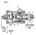
- FIG. 1 shows the scanning device with the signal transmitter
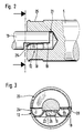
- FIG. 2 shows a section through the scanning shaft
- FIG. 3 shows a section through the potentiometer shaft in the area of its flattening.
- a load-dependent braking force control device has a scanning device for the distance between a vehicle axle 1 and a vehicle body 2 that changes in the event of load changes.
- This scanning device is designed as a lever 3, which sits on the end 4 of a scanning shaft 5 and can rotate it.
- the scanning shaft 5 is received by a housing 6, which also receives a rotary potentiometer 7 and a return spring 8.
- the latter surrounds the scanning shaft 5 and is inserted at one end into a housing wall 10 and at the other end into a diametral bore 11 of the scanning shaft 5.
- the scanning shaft 5 is connected via a plug-in coupling 12 to a potentiometer shaft 15; Therefore, the return spring 8 also serves as a reset for the potentiometer 7 adjustable by the potentiometer shaft 13.
- the potentiometer 7 is a signal generator for a signal receiver 19, which is designed as a solenoid valve and is arranged in a brake line 17 leading to wheel brake cylinders 16.
- the plug-in coupling 12 between the sensing shaft 5 and the potentiometer shaft 13 is formed by a leaf spring 18 formed as an intermediate part and a flat 19 at the end of the potentiometer shaft 13 and a transverse opening 20 in the sensing shaft 5.
- the latter is with one Provide blind hole 21, which is intended for receiving the flattened end of the potentiometer shaft 13.
- the leaf spring 18 has a center piece 22 with which it rests firmly on the flat 19 under pretension.
- the leaf spring 18 is bent at both ends, one end 23 being bent through 180 ° and clamped in the transverse opening 20 like a clamp, while the other end 24 has a curvature which corresponds to and with the shape of an outer annular groove 25 of the scanning shaft 5 curved end 24, it is inserted into the outer ring groove 25.
- the leaf spring 18 is fixed in the axial direction.
- the center piece 22 has an outwardly threading slide-on tongue 26 which is intended, after the mounting of the leaf spring 18 in the transverse opening 20, to press the potentiometer shaft 13 with its flattening into the leaf spring 18 in the radial direction and thus to couple the plug-in coupling 12.
- connection of the clutch 12 is created only by radially pressing in the potentiometer shaft 13.
- the preload and the tensioning of the leaf spring 18 in the transverse opening create a completely play-free coupling between the potentiometer 7 and the sensing shaft 5; this is also because the potentiometer shaft 13 can be rotated very easily.
Landscapes
- Engineering & Computer Science (AREA)
- Transportation (AREA)
- Mechanical Engineering (AREA)
- Regulating Braking Force (AREA)
- Mechanical Control Devices (AREA)
- Braking Arrangements (AREA)
Abstract
Description
- Die Erfindung geht aus von einer lastabhängigen Bremskraftregeleinrichtung nach der Gattung des Hauptanspruchs. Eine derartige Bremskraftregeleinrichtung ist bekannt (DE-OS 35 25 835).
- Bei dieser bekannten Bremskraftregeleinrichtung wird zwar auch ein Potentiometer verwendet, dieser spricht aber auf Längsverstellung an und wird über einen Exzenter angetrieben. Auf diese Weise entsteht zwischen der Abtastvorrichtung und dem Signalgeber viel Spiel, was einer genauen Übertragung von Eingangs- zu Ausgangssignalen abträglich ist.
- Die lastabhängige Bremskraftregeleinrichtung mit den kennzeichnenden Merkmalen des Hauptanspruchs hat demgegneüber den Vorteil, daß kein Spiel zwischen der Abtastwelle und der Potentiometerwelle besteht.
- Damit ist eine sehr genaue Übertragung von Eingangs- zu Ausgangssignalen gewährleistet.
- Ein Ausführungsbeispiel der Erfindung ist in der Zeichnung dargestellt und in der nachfolgenden Beschreibung näher erläutert. Es zeigen: Figur 1 die Abtastvorrichtung mit dem Signalgeber, Figur 2 einen Schnitt durch die Abtastwelle und Figur 3 einen Schnitt durch die Potentiometerwelle in dem Bereich von deren Abflachung.
- Eine lastabhängige Bremskraftregeleinrichtung besitzt eine Abtastvorrichtung für den bei Lastveränderungen wechselnden Abstand zwischen einer Fahrzeugachse 1 und einem Fahrzeug-Aufbau 2. Diese Abtastvorrichtung ist als Hebel 3 ausgebildet, der auf dem Ende 4 einer Abtastwelle 5 sitzt und diese verdrehen kann.
- Die Abtastwelle 5 wird von einem Gehäuse 6 aufgenommen, das auch noch einen Drehpotentiometer 7 und eine Rückstellfeder 8 aufnimmt. Letztere umgibt die Abtastwelle 5 und ist mit ihrem einen Ende in eine Gehäusewand 10 und mit ihrem anderen Ende in eine Diametral-Bohrung 11 der Abtastwelle 5 eingesetzt. Die Abtastwelle 5 ist über eine Steckkupplung 12 mit einer Potentiometerwelle 15 verbunden; deshalb dient die Rückstellfeder 8 auch als Rücksteller für den von der Potentiometerwelle 13 verstellbaren Potentiometer 7. Der Potentiometer 7 ist Signalgeber für einen Signalempfänger 19, der als Magnetventil ausgebildet ist und in einer zu Radbremszylindern 16 führenden Bremsleitung 17 angeordnet ist.
- In den Schnittbildern nach den Figuren 2 und 3 ist zu erkennen, daß die Steckkupplung 12 zwischen Abtastwelle 5 und Potentiometerwelle 13 durch eine als Zwischenteil ausgebildete Blattfeder 18 und eine Abflachung 19 am Ende der Potentiometerwelle 13 und einen Querdurchbruch 20 in der Abtastwelle 5 gebildet ist. Letztere ist mit einer Sackbohrung 21 versehen, die zur Aufnahme des abgeflachten Endes der Potentiometerwelle 13 bestimmt ist.
- Die Blattfeder 18 weist ein Mittelstück 22 auf, mit dem sie unter Vorspannung fest auf der Abflachung 19 aufliegt. An ihren beiden Enden ist die Blattfeder 18 umgebogen, wobei das eine Ende 23 um 180° umgebogen und in dem Querdurchbruch 20 klammerartig verspannt ist, während das andere Ende 24 eine Krümmung aufweist, die der Form einer Außenringnut 25 der Abtastwelle 5 entspricht und mit diesem gekrümmten Ende 24 ist sie in die Außenringnut 25 eingelegt. Dadurch ist die Blattfeder 18 in axialer Richtung festgelegt. Das Mittelstück 22 hat eine nach außen weisende Einfädel-Aufgleitzunge 26, die dazu bestimmt ist, nach der Montage der Blattfeder 18 in dem Querdurchbruch 20 die Potentiometerwelle 13 mit ihrer Abflachung in die Blattfeder 18 in radialer Richtung einzudrücken und damit die Steckkupplung 12 zu kuppeln.
- Es ist zu bemerken, daß die Verbindung der Kupplung 12 lediglich durch radiales Eindrücken der Potentiometerwelle 13 entsteht. Durch die Vorspannung und die Verspannung der Blattfeder 18 in dem Querdurchbruch ist auf diese Weise eine völlig spielfreie Kupplung zwischen dem Potentiometer 7 und der Abtastwelle 5 geschaffen; dies auch deshalb, weil sich die Potentiometerwelle 13 sehr leicht drehen läßt.
Claims (5)
Applications Claiming Priority (2)
| Application Number | Priority Date | Filing Date | Title |
|---|---|---|---|
| DE8710867U DE8710867U1 (de) | 1987-08-08 | 1987-08-08 | Lastabhängige Bremskraftregeleinrichtung |
| DE8710867U | 1987-08-08 |
Publications (3)
| Publication Number | Publication Date |
|---|---|
| EP0303073A2 true EP0303073A2 (de) | 1989-02-15 |
| EP0303073A3 EP0303073A3 (en) | 1990-06-13 |
| EP0303073B1 EP0303073B1 (de) | 1993-03-24 |
Family
ID=6810927
Family Applications (1)
| Application Number | Title | Priority Date | Filing Date |
|---|---|---|---|
| EP88111646A Expired - Lifetime EP0303073B1 (de) | 1987-08-08 | 1988-07-20 | Lastabhängige Bremskraftregeleinrichtung |
Country Status (2)
| Country | Link |
|---|---|
| EP (1) | EP0303073B1 (de) |
| DE (2) | DE8710867U1 (de) |
Family Cites Families (2)
| Publication number | Priority date | Publication date | Assignee | Title |
|---|---|---|---|---|
| DE1851819U (de) * | 1961-11-21 | 1962-05-17 | Rondo Werke G M B W | Anordnung zur verbindung von welle und radnabe eines maschinentriebes zur uebertragung von drehmomenten, insbesondere bei periodish wechselnder drehrichtung. |
| DE2048965B2 (de) * | 1970-10-06 | 1973-03-08 | Westinghouse Bremsen u Apparate bau GmbH, 3000 Hannover | Einrichtung zum druckabhaengigen verstellen eines gebers fuer eine elektrische steuergroesse |
-
1987
- 1987-08-08 DE DE8710867U patent/DE8710867U1/de not_active Expired
-
1988
- 1988-07-20 DE DE8888111646T patent/DE3879578D1/de not_active Expired - Fee Related
- 1988-07-20 EP EP88111646A patent/EP0303073B1/de not_active Expired - Lifetime
Also Published As
| Publication number | Publication date |
|---|---|
| EP0303073A3 (en) | 1990-06-13 |
| DE3879578D1 (de) | 1993-04-29 |
| DE8710867U1 (de) | 1988-12-08 |
| EP0303073B1 (de) | 1993-03-24 |
Similar Documents
| Publication | Publication Date | Title |
|---|---|---|
| DE3235288C2 (de) | Tretkurbelantrieb für ein Fahrrad | |
| DE3872847T2 (de) | Vorrichtung zur sicherstellung der feineinstellung der winkellage eines lenkrades auf einer lenksaeule. | |
| DE102017124470A1 (de) | Toleranzausgleichsanordnung | |
| DE19503722A1 (de) | Schlauchanschluß, insbesondere zum Anschluß von Schläuchen, wie Gartenschläuchen | |
| DE2333040A1 (de) | Feste verbindung eines wellenzapfens mit der nabe eines anschlussorgans, beispielsweise der gabel eines drehgelenks | |
| DE4209835A1 (de) | Kugelverbindung | |
| EP1257744B1 (de) | Befestigungsvorrichtung zur festlegung eines seilzuges | |
| DE69111749T2 (de) | Steuerseilselbsteinstellvorrichtung. | |
| EP0790423A1 (de) | Verfahren zur Herstellung einer Vorrichtung zum Verbinden eines kerbverzahnten, der Übertragung von Drehmomenten dienenden Wellenzapfens | |
| WO2004088263A9 (de) | Vorrichtung zum erfassen einer betätigungskraft eines bremspedals und bremsanlage | |
| EP0851824B1 (de) | Zugsattelzapfen für sattelanhänger und befestigungsanordnung | |
| EP0278995A1 (de) | Steckbolzen und Vorrichtung zu seiner Montage | |
| DE3213657A1 (de) | Abstuetzung fuer eine macpherson-federbein-aufhaengung fuer kraftfahrzeuge | |
| EP0303073A2 (de) | Lastabhängige Bremskraftregeleinrichtung | |
| EP3774497B1 (de) | Lenkvorrichtung mit simuliertem lenkwiderstandsmoment | |
| DE2640770A1 (de) | Servoeinrichtung | |
| DE3203495C2 (de) | Vorrichtung zur gemeinsamen Befestigung eines Bremskraftverstärkers und eines Hauptbremszylinders am Kraftfahrzeug | |
| DE19709387C2 (de) | Ausrückvorrichtung für eine Reibungskupplung | |
| DE3503749C2 (de) | ||
| EP0272389B1 (de) | Selbsttätige Nachstellvorrichtung für eine Scheibenbremse | |
| DE3305417C1 (de) | Verstellvorrichtung für mechanische Zug- und Druckmittelverbindungen | |
| DE3603145A1 (de) | Druckmittel-bremszylinder | |
| DE102024205638A1 (de) | Vorrichtung zum Ausgleichen von Toleranzen zwischen zwei miteinander zu verbindenden Bauteilen | |
| DE102006004048B4 (de) | Befestigungseinrichtung zur Verwendung bei einer Wischanlage für Fahrzeuge sowie Wischanlage | |
| CH682184A5 (en) | Plug connector for optical fibre cable - has outer coupling sleeve attached to housing of plug fitting via safety coupling which may be turned when coupling force exceeded |
Legal Events
| Date | Code | Title | Description |
|---|---|---|---|
| PUAI | Public reference made under article 153(3) epc to a published international application that has entered the european phase |
Free format text: ORIGINAL CODE: 0009012 |
|
| AK | Designated contracting states |
Kind code of ref document: A2 Designated state(s): DE FR IT SE |
|
| PUAL | Search report despatched |
Free format text: ORIGINAL CODE: 0009013 |
|
| AK | Designated contracting states |
Kind code of ref document: A3 Designated state(s): DE FR IT SE |
|
| 17P | Request for examination filed |
Effective date: 19901027 |
|
| RAP3 | Party data changed (applicant data changed or rights of an application transferred) |
Owner name: ROBERT BOSCH GMBH |
|
| 17Q | First examination report despatched |
Effective date: 19920421 |
|
| GRAA | (expected) grant |
Free format text: ORIGINAL CODE: 0009210 |
|
| AK | Designated contracting states |
Kind code of ref document: B1 Designated state(s): DE FR IT SE |
|
| PG25 | Lapsed in a contracting state [announced via postgrant information from national office to epo] |
Ref country code: IT Free format text: LAPSE BECAUSE OF FAILURE TO SUBMIT A TRANSLATION OF THE DESCRIPTION OR TO PAY THE FEE WITHIN THE PRE;WARNING: LAPSES OF ITALIAN PATENTS WITH EFFECTIVE DATE BEFORE 2007 MAY HAVE OCCURRED AT ANY TIME BEFORE 2007. THE CORRECT EFFECTIVE DATE MAY BE DIFFERENT FROM THE ONE RECORDED.SCRIBED TIME-LIMIT Effective date: 19930324 Ref country code: FR Effective date: 19930324 Ref country code: SE Effective date: 19930324 |
|
| REF | Corresponds to: |
Ref document number: 3879578 Country of ref document: DE Date of ref document: 19930429 |
|
| EN | Fr: translation not filed | ||
| PLBE | No opposition filed within time limit |
Free format text: ORIGINAL CODE: 0009261 |
|
| STAA | Information on the status of an ep patent application or granted ep patent |
Free format text: STATUS: NO OPPOSITION FILED WITHIN TIME LIMIT |
|
| 26N | No opposition filed | ||
| PG25 | Lapsed in a contracting state [announced via postgrant information from national office to epo] |
Ref country code: DE Effective date: 19940401 |