EP0303034A2 - Method and device for sorting refuse - Google Patents
Method and device for sorting refuse Download PDFInfo
- Publication number
- EP0303034A2 EP0303034A2 EP19880110265 EP88110265A EP0303034A2 EP 0303034 A2 EP0303034 A2 EP 0303034A2 EP 19880110265 EP19880110265 EP 19880110265 EP 88110265 A EP88110265 A EP 88110265A EP 0303034 A2 EP0303034 A2 EP 0303034A2
- Authority
- EP
- European Patent Office
- Prior art keywords
- sorting device
- garbage sorting
- steep surface
- steep
- garbage
- Prior art date
- Legal status (The legal status is an assumption and is not a legal conclusion. Google has not performed a legal analysis and makes no representation as to the accuracy of the status listed.)
- Granted
Links
Images

Classifications
-
- B—PERFORMING OPERATIONS; TRANSPORTING
- B07—SEPARATING SOLIDS FROM SOLIDS; SORTING
- B07B—SEPARATING SOLIDS FROM SOLIDS BY SIEVING, SCREENING, SIFTING OR BY USING GAS CURRENTS; SEPARATING BY OTHER DRY METHODS APPLICABLE TO BULK MATERIAL, e.g. LOOSE ARTICLES FIT TO BE HANDLED LIKE BULK MATERIAL
- B07B4/00—Separating solids from solids by subjecting their mixture to gas currents
- B07B4/02—Separating solids from solids by subjecting their mixture to gas currents while the mixtures fall
-
- B—PERFORMING OPERATIONS; TRANSPORTING
- B03—SEPARATION OF SOLID MATERIALS USING LIQUIDS OR USING PNEUMATIC TABLES OR JIGS; MAGNETIC OR ELECTROSTATIC SEPARATION OF SOLID MATERIALS FROM SOLID MATERIALS OR FLUIDS; SEPARATION BY HIGH-VOLTAGE ELECTRIC FIELDS
- B03B—SEPARATING SOLID MATERIALS USING LIQUIDS OR USING PNEUMATIC TABLES OR JIGS
- B03B9/00—General arrangement of separating plant, e.g. flow sheets
- B03B9/06—General arrangement of separating plant, e.g. flow sheets specially adapted for refuse
-
- B—PERFORMING OPERATIONS; TRANSPORTING
- B07—SEPARATING SOLIDS FROM SOLIDS; SORTING
- B07B—SEPARATING SOLIDS FROM SOLIDS BY SIEVING, SCREENING, SIFTING OR BY USING GAS CURRENTS; SEPARATING BY OTHER DRY METHODS APPLICABLE TO BULK MATERIAL, e.g. LOOSE ARTICLES FIT TO BE HANDLED LIKE BULK MATERIAL
- B07B13/00—Grading or sorting solid materials by dry methods, not otherwise provided for; Sorting articles otherwise than by indirectly controlled devices
- B07B13/003—Separation of articles by differences in their geometrical form or by difference in their physical properties, e.g. elasticity, compressibility, hardness
-
- B—PERFORMING OPERATIONS; TRANSPORTING
- B07—SEPARATING SOLIDS FROM SOLIDS; SORTING
- B07B—SEPARATING SOLIDS FROM SOLIDS BY SIEVING, SCREENING, SIFTING OR BY USING GAS CURRENTS; SEPARATING BY OTHER DRY METHODS APPLICABLE TO BULK MATERIAL, e.g. LOOSE ARTICLES FIT TO BE HANDLED LIKE BULK MATERIAL
- B07B13/00—Grading or sorting solid materials by dry methods, not otherwise provided for; Sorting articles otherwise than by indirectly controlled devices
- B07B13/08—Grading or sorting solid materials by dry methods, not otherwise provided for; Sorting articles otherwise than by indirectly controlled devices according to weight
-
- Y—GENERAL TAGGING OF NEW TECHNOLOGICAL DEVELOPMENTS; GENERAL TAGGING OF CROSS-SECTIONAL TECHNOLOGIES SPANNING OVER SEVERAL SECTIONS OF THE IPC; TECHNICAL SUBJECTS COVERED BY FORMER USPC CROSS-REFERENCE ART COLLECTIONS [XRACs] AND DIGESTS
- Y02—TECHNOLOGIES OR APPLICATIONS FOR MITIGATION OR ADAPTATION AGAINST CLIMATE CHANGE
- Y02W—CLIMATE CHANGE MITIGATION TECHNOLOGIES RELATED TO WASTEWATER TREATMENT OR WASTE MANAGEMENT
- Y02W30/00—Technologies for solid waste management
- Y02W30/50—Reuse, recycling or recovery technologies
- Y02W30/52—Mechanical processing of waste for the recovery of materials, e.g. crushing, shredding, separation or disassembly
Definitions
- the invention relates to a method for sorting waste according to the preamble of claim 1 and a waste sorting device for performing the method.
- the object of the invention is accordingly to provide a method for sorting waste and a device for this, with the aid of which an early splitting of waste streams is possible, so that the mechanical sorting as well as the manual reading can subsequently be carried out with better effectiveness.
- this object is achieved on the basis of the method according to the preamble of claim 1 with the characterizing features of this claim. Furthermore, the invention is achieved by a garbage sorting device for carrying out the method according to claim 1 with the characterizing features of claim 2.
- the invention takes into account the knowledge that flat and light components make up an essential part of the garbage. This applies in particular if the waste contains at least a large part commercial waste. In such cases, the waste stream can be split in a targeted manner if flat, lighter components, such as paper, cardboard, wooden or plastic plates, textiles and the like. Like. Be sorted out early. This is made possible by the steep surface against which such materials are sucked and to which they then adhere, while other, in particular heavy materials such as bottles, but also lighter physical objects such as plastic containers, fall down. At the same time, dusty or fine particles can be extracted through the steep surface through a third separation branch.
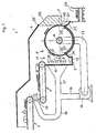
- Sorting device comprises, in a housing shown with individual walls 2, 3, two belt conveyors 4, 5 connected in series, which lead to a sieve drum 6, which, according to an arrow 7, rotate clockwise and thus on the side facing the feed conveyors 4, 5 about a horizontal axis of rotation 8 turns upwards.
- the screen space 6 is opposite a screen wall 10 and a chute 11 is formed between the two and ends in a conveyor trough 12 on the underside.
- the sieve drum 6 is connected on the inside via a suction pipe 13 to the suction side of a blower 14 and is thus able to suck in material falling in the chute 11 and, in any case, to adhere it to the top when this material is flat and, based on the contact surface, does not close is difficult. Heavier and in particular non-flat pieces of material in a waste stream supplied via the conveyors 4 and 5 cannot hold onto the screening drum and fall into the conveyor trough 12, from where they are transported away in a conventional manner.
- a directed cross-air flow is formed in accordance with the arrows 15 from the screen wall 10 to the steep surface 9, with a blower duct 16, 17 leading from the blower 14 to the screen wall on the pressure side and blowing air on it
- Closed recirculation duct 13, 16, 17 also has the advantage that the air loaded with fine parallels is not mixed with the outside air and the contaminants do not get out. In this respect, the effectiveness of filters which (not shown) are provided in the suction line 13 is not important.
- a branch line 18 leads from the pressure line 16 to an orifice 19, in front of which the supplied material from the conveyor 4 falls on the conveyor 5. Blowing at this point has the effect of moving and separating the material. This also promotes the efficiency of the separation provided on the screen drum 6.
- the flat material drawn off from the falling material flow by the sieve drum 6 is discharged on the side remote from the steep surface 9 in the region of an ejection opening 20, a wiping edge 21 on a slide 22 leading close to the sieve drum 6.
- the stripped and slipping material arrives in a conveyor trough 23 and thus takes a different route to the material falling into the conveyor trough 12.
- the sieve drum 6 extends outside the housing.
- a cover 25 is arranged on the inside of the drum, which closes the aforementioned area and rests on the end of the screen drum with sealing edges 26, 27. It is quite desirable for the material to be ejected towards the conveyor trough 23 that the suction effect in the area of the scraper edge 21 is eliminated. In this sense, the cover 25 together with the scraper edge 27 can also be pulled up (at most up to the vertical plane through the axis 8).
- the suction effect left on the right drum side is used to attract a flap 28 against the sieve drum.
- the system is also improved by the dead weight of the flap, the focus of which in the drawing is on the right of a hinge 29 as a connection to the housing wall 2. With this flap, the large-scale entry of incorrect air is prevented, but at the same time the ejection of material is ensured.
- the device 1 represents a largely closed system with regard to the air flow.
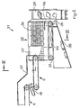
- the device shown in FIGS. 2 and 3, designated overall by 31, represents a modification compared to device 1 described above with reference to FIG. 1 in that it does not use a sieve drum with a horizontal axis, but rather a conveyor belt 32, which is between two rollers 33 , 34 revolves with (parallel to one another) inclined, namely laterally inclined axes (cf. axis 35 in FIG. 3). With its inclined surface, the conveyor belt 32 forms a steep surface 36 with a plurality of conveying directions, in that material arriving from left to right via feed conveyors 4 and 5 (corresponding to those in FIG.
- the steep face 36 is acted upon with suction air at the rear.
- FIG. 3 it can be seen with a section through the conveyor belt 32 that this encloses a fixed suction box 40 which has closed walls 41, 42 on several sides, but has a support surface 43 with large openings toward the steep face 36.
- the suction box 40 opens into a suction line 44 to a blower 45.
- the function of the device 31 differs from that of the device 1 in that the material is not sucked from a material flow in free fall, but that it is heaped onto the steep surface, from where it either passes through the steep surface 36 under the suction effect of the air flow clings or rolls off at an angle or slips.
- the separation effect is also served by a guide rail 46 at the rear and lower end of the steep face, which ensures that detachable sheet material still gets into the conveyor trough 30.
- the suction box 40 takes on the one hand the function of the cover 25 in the device according to FIG. 1, but allows a simple design in connection with a conveyor belt.
- the device 31 is also not hermetically encapsulated by a housing.
- a housing part 47 ends in front of the steep surface 36 of the conveyor belt 32 and is essentially limited to air guiding functions with regard to the blower mouth 19. Although this embodiment does not achieve a hermetic seal of the air guiding, it allows a simple construction of the device without the need for critical seals.
- the angle of inclination of the steep face 36 is 35 ° in the case shown, which is sufficient in most applications.
- steeper angles approximately 45 ° and higher, can be provided.
- a fan with a high suction capacity of, for example, 20,000 m 3 per hour is provided.
- a width of more than 0.5 m, expediently approximately 1 m, and a length of more than 0.5 m expediently 1.5 m are required.
- the perforation of the screen surface is assumed to be more than 50%.
- wire mesh belts, single belts or crossbar belts can also be used in addition to sieve belts.
- the suction box 40 the person skilled in the art also readily has surface elements which, on the one hand, are permeable to air and, on the other hand, enable the screen conveyor to be supported to any desired extent.
- the suction box 40 can also hold filter material or surface filters for trapping dusty fine particles.
- the steep surface is movable, namely as part of a sieve drum or a belt. It goes without saying that a fixed steep surface can in principle be provided in order to adhere light and flat material from a falling or sliding stream of material. This material could then be removed from the steep surface by wipers, likewise it can be provided in an intermittent operation that after the removal of heavy or rolling material the air flow through the steep surface is switched off or vice versa, in order to then throw off the flat and light material.
Abstract
Description
Die Erfindung betrifft ein Verfahren zur Müllsortierung nach dem Oberbegriff des Anspruchs 1 sowie eine Müllsortiervorrichtung zur Durchführung des Verfahrens.The invention relates to a method for sorting waste according to the preamble of claim 1 and a waste sorting device for performing the method.
Zur Sortierung von Müll mit dem Ziel, wiederverwertbare Bestandteile rückzugewinnen und alles übrige möglichst unkritisch und kostensparend beseitigen zu können, haben sich kombinierte Verfahren bewährt, bei denen verschiedene Maßnahmen zum Trennen des Materialgemisches wie etwa das Sieben nach Größenordnungen, die Magnetabscheidung ferromagnetischer Bestandteile und nicht zuletzt das Verlesen von Hand Anwendung finden. Für die Effektivität der verschiedenen Maßnahmen ist es allerdings wichtig, daß der zu bearbeitende Müllstrom schon vorher durch Aussondern nicht in Betracht kommender Bestandteile reduziert wird.Combined processes have proven themselves for sorting waste with the aim of recovering recyclable components and eliminating everything else as uncritically and cost-effectively as possible, in which various measures for separating the material mixture, such as sieving by order of magnitude, magnetic separation of ferromagnetic components and last but not least hand-reading is used. For the effectiveness of the various measures, however, it is important that the waste stream to be processed is reduced beforehand by eliminating components that are not considered.
Aufgabe der Erfindung ist es dementsprechend, ein Verfahren zur Müllsortierung sowie eine Vorrichtung hierfür zu schaffen, mit Hilfe derer eine frühzeitige Aufspaltung von Müllströmen möglich wird, so daß die maschinelle Sortierung wie auch das Verlesen von Hand nachfolgend mit besserer Effektivität durchgeführt werden kann.The object of the invention is accordingly to provide a method for sorting waste and a device for this, with the aid of which an early splitting of waste streams is possible, so that the mechanical sorting as well as the manual reading can subsequently be carried out with better effectiveness.
Gemäß der Erfindung wird diese Aufgabe von einem Verfahren nach dem Oberbegriff des Anspruchs 1 ausgehend mit den kennzeichnenden Merkmalen dieses Anspruchs gelöst. Weiterhin wird die Erfindung von einer Müllsortiervorrichtung zur Durchführung des Verfahrens nach Anspruch 1 ausgehend mit den kennzeichnenden Merkmalen des Anspruchs 2 gelöst.According to the invention, this object is achieved on the basis of the method according to the preamble of claim 1 with the characterizing features of this claim. Furthermore, the invention is achieved by a garbage sorting device for carrying out the method according to claim 1 with the characterizing features of claim 2.
Die Erfindung trägt der Erkenntnis Rechnung, daß flächige und leichte Bestandteile einen wesentlichen Teil des Mülls ausmachen. Dies gilt insbesondere dann, wenn der Müll zumindest großenteils gewerbliche Abfälle enthält. In solchen Fällen läßt sich der Müllstrom zielgerecht aufspalten, wenn flächige, leichtere Bestandteile, wie Papier, Pappe, Holz- oder Kunststoffplatten, Textilien u. dgl. frühzeitig ausgesondert werden. Dies wird durch die Steilfläche ermöglicht, gegen die derartige Materialien angesaugt werden und an der sie dann haften, während andere, insbesondere schwere Materialien wie Flaschen, aber auch leichtere körperliche Gegenstände wie Kunststoffbehälter, nach unten fallen. Gleichzeitig kann eine Absaugung staubiger oder feiner Partikel durch die Steilfläche hindurch einen dritten Absonderungszweig bewirken.The invention takes into account the knowledge that flat and light components make up an essential part of the garbage. This applies in particular if the waste contains at least a large part commercial waste. In such cases, the waste stream can be split in a targeted manner if flat, lighter components, such as paper, cardboard, wooden or plastic plates, textiles and the like. Like. Be sorted out early. This is made possible by the steep surface against which such materials are sucked and to which they then adhere, while other, in particular heavy materials such as bottles, but also lighter physical objects such as plastic containers, fall down. At the same time, dusty or fine particles can be extracted through the steep surface through a third separation branch.
Damit lassen sich Papier, Pappe und flächiger, insbesondere großflächiger Abfall aus dem Müllstrom herausziehen und - ggf. nach weiterer Siebung oder sonstiger Klassierung - rückgewinnen.This allows paper, cardboard and flat, especially large-scale waste to be extracted from the waste stream and - if necessary after further screening or other classification - recovered.
Gleichzeitig wird der Strom des restlichen Materials, insbesondere der Flaschen und Kunststoffbehälter, überschaubar und einfacher zu sortieren. Die abgesaugten Feinpartikel werden regelmäßig in Filtern aufzufangen und in herkömmlicher Weise abzulagern sein.At the same time, the flow of the rest of the material, especially the bottles and plastic containers, becomes manageable and easier to sort. The extracted fine particles will regularly be collected in filters and deposited in a conventional manner.
Weitere Merkmale und Vorteile der Erfindung ergeben sich aus den Ansprüchen und der nachfolgenden Beschreibung, in der zwei Ausführungsbeispiele des Gegenstands der Erfindung anhand einer Zeichnung näher erläutert sind. In der Zeichnung zeigen in jeweils schematisierter Wiedergabe:
- Fig. 1 schnittbildliche Seitenansicht einer ersten Müllsortiervorrichtung,
- Fig. 2 schnittbildliche Seitenansicht einer zweiten Müllsortiervorrichtung und
- Fig. 3 Schnitt nach Linie III-III in Fig. 2.
- 1 sectional side view of a first waste sorting device,
- Fig. 2 sectional side view of a second waste sorting device and
- 3 section along line III-III in Fig. 2nd
Die in Fig. 1 dargestellte, insgesamt mit 1 bezeichnete Müll sortiervorrichtung umfaßt in einem mit einzelnen Wänden 2,3 wiedergegebenen Gehäuse zwei hintereinandergeschaltete Bandförderer 4,5, die auf eine Siebtrommel 6 hinführen, die sich entsprechend einem Pfeil 7 in Uhrzeigerrichtung und somit auf der den Zuförderern 4,5 zugewandten Seite um eine waagerechte Drehachse 8 aufwärts dreht.The garbage shown in Fig. 1, generally designated 1 Sorting device comprises, in a housing shown with
In diesem Bereich des Aufwärtsdrehens, der nachfolgend als Steilfläche 9 bezeichnet werden soll, steht der Siebraum 6 einer Siebwand 10 gegenüber und zwischen beiden ist ein Fallschacht 11 ausgebildet, der unterseitig in einer Förderrinne 12 endet.In this area of the upward rotation, which will be referred to as steep face 9 below, the
Die Siebtrommel 6 ist innenseitig über ein Saugrohr 13 mit der Saugseite eines Gebläses 14 verbunden und damit in der Lage, im Fallschacht 11 niedergehendes Material anzusaugen und jedenfalls dann anhaftend nach oben zu fördern, wenn dieses Material flächig und, bezogen auf die Anlagefläche, nicht zu schwer ist. Schwerere und insbesondere nicht flächig ausgebildete Materialstücke in einem über die Förderer 4 und 5 zugeführten Müllstrom vermögen sich an der Siebtrommel nicht zu halten und fallen in die Förderrinne 12, von wo sie in einer üblichen Weise abtransportiert werden.The
Um die Trennfunktion der Vorrichtung zu intensivieren, wird ein gerichteter Querluftstrom entsprechend den Pfeilen 15 hindurch von der Siebwand 10 zur Steilfläche 9 hin ausgebildet, wobei ein Gebläsekanal 16,17 druckseitig von dem Gebläse 14 zu der Siebwand hinführt und diese mit Blasluft beaufschlagt.Der insoweit geschlossene Umluftkanal 13,16,17 hat überdies den Vorteil, daß die mit Feinparatikeln belastete Luft nicht mit der Außenluft vermischt wird und die Verschmutzungen nicht nach außen gelangen. Insoweit kommt es nicht auf die Wirksamkeit von Filtern an, die (nicht eingezeichnet) in der Saugleitung 13 vorgesehen sind.In order to intensify the separating function of the device, a directed cross-air flow is formed in accordance with the
Eine Zweigleitung 18 führt von der Druckleitung 16 zu einer Mündung 19, vor der das zugeführte Material von dem Förderer 4 auf den Förderer 5 fällt. Eine Blaseinwirkung an dieser Stelle hat die Wirkung, daß das Material bewegt und entmischt wird. Dieses fördert gleichfalls den Wirkungsgrad der an der Siebtrommel 6 vorgesehenen Trennung.A
Das von der Siebtommel 6 aus dem fallenden Materialstrom abgezogene flächige Material wird auf der der Steilfläche 9 abgelegenen Seite im Bereich einer Auswurföffnung 20 ausgetragen, wobei eine Abstreifkante 21 an einer Rutsche 22 dicht an die Siebtrommel 6 heranführt. Das abgestreifte und niederrutschende Material gelangt in eine Förderrinne 23 und geht somit einen anderen Weg an das in die Förderrinne 12 niederfallende Material.The flat material drawn off from the falling material flow by the
Zwischen der Abstreifkante 21 und einer eng an die Siebtrommel herangeführten Abschlußkante 24 des Gehäuseteils 3 verläuft die Siebtrommel 6 außerhalb des Gehäuses. Um in diesem Bereich eine unerwünschte Ansaugung von Außenluft zu unterbinden, ist auf der Trommelinnenseite eine Abdeckung 25 angeordnet, die den vorgenannten Bereich schließt und endseitig mit Dichtkanten 26,27 an der Siebtrommel anliegt. Dabei ist es für ein Auswerfen des Materials zur Förderrinne 23 hin durchaus erwünscht, daß die Saugwirkung im Bereich der Abstreifkante 21 entfällt. In diesem Sinne kann die Abdeckung 25 mitsamt der Abstreifkante 27 auch noch (maximal etwa bis zur Vertikalebene durch die Achse 8) hochgezogen werden.Between the
Im vorliegenden Fall wird die auf der rechten Trommelseite belassene Saugwirkung dazu verwandt, eine Klappe 28 gegen die Siebtrommel anzuziehen. Die Anlage wird auch durch das Eigengewicht der Klappe verbessert, deren Schwerpunkt in der Zeichnung insgesamt rechts von einem Scharnier 29 als Verbindung zu der Gehäusewand 2 liegt. Mit dieser Klappe wird der großflächige Eintritt von Fehlluft unterbunden, gleichzeitig aber der Auswurf von Material gesichert. Insgesamt stellt die Vorrichtung 1 ein hinsichtlich der Luftführung weitgehend geschlossenes System dar.In the present case, the suction effect left on the right drum side is used to attract a
Die in den Fig. 2 und 3 dargestellte, insgesamt mit 31 bezeichnete Vorrichtung stellt gegenüber oben anhand der Fig. 1 beschriebenen Vorrichtung 1 eine Abwandlung insofern dar, als diese keine Siebtrommel mit horizontaler Achse, sondern ein Förderband 32 verwendet, das zwischen zwei Rollen 33,34 mit (zueinander parallelen) schrägen, nämlich seitlich geneigten Achsen umläuft (vgl. Achse 35 in Fig. 3). Das Förderband 32 bildet mit seiner schrägen Oberfläche eine Steilfläche 36 mit mehreren Förderrichtungen, indem über Zuförderer 4 und 5 (entsprechend denen in Fig. 1) von links nach rechts ankommendes und über ein Leitblech 37 auf die Steilfläche 36 aufgebrachtes Material zum einen entsprechend der Fallinie quer in eine Förderrinne 38 abgleiten oder vor allem abrollen kann, während am Förderer anhaftends Material nach rechts in eine zweite Förderrinne 39 transportiert wird. Ein dritter Materialstrom feinen Leichten, insbesondere staubigen Materials ist durch die perforierte Steilfläche hindurch gegeben.The device shown in FIGS. 2 and 3, designated overall by 31, represents a modification compared to device 1 described above with reference to FIG. 1 in that it does not use a sieve drum with a horizontal axis, but rather a
Auch hier ist für den Transport des Feinmaterials und insbesondere für das Separieren flächigen Materials aus dem Materialstrom vorgesehen, daß die Steilfläche 36 rückwärtig mit Saugluft beaufschlagt wird.Here, too, for the transport of the fine material and in particular for the separation of flat material from the material flow, it is provided that the
Aus Fig. 3 wird mit einem Schnitt durch das Förderband 32 sichtbar, daß dieses einen feststehenden Saugkasten 40 umschließt, der auf mehreren Seiten geschlossene Wandungen 41,42 aufweist, zur Steilfäche 36 hin aber eine stützfläche 43 mit großflächigen Öffnungen aufweist. Der Saugkasten 40 mündet in eine Saugleitung 44 zu einem Gebläse 45 hin ein.From Fig. 3 it can be seen with a section through the
Die Funktion der Vorrichtung 31 unterscheidet sich von der der Vorrichtung 1 darin, daß das Material nicht im freien Fall aus einem Materialstrom abgesaugt wird, sondern daß es auf die Steilfläche aufgeschüttet wird, von wo es entweder unter der Saugwirkung des Luftstroms durch die steilfläche 36 hindurch anhaftet oder aber schräg abrollt bzw. abrutscht. Der Trennungswirkung dient dabei auch eine Führungsschiene 46 an dem hinteren und unteren Ende der Steilfläche, die dafür sorgt, daß sich ablösendes Flächenmaterial noch in die Förderrinne 30 gelangt.The function of the
Unabhängig von der Sortierfunktion der Vorrichtung sind die Unterschiede in der Luftführung zu betrachten. Der Saugkasten 40 übernimmt dabei zum einen die Funktion der Abdeckung 25 bei der Vorrichtung gemäß Fig. 1, gestattet dabei aber in Verbindung mit einem Förderband eine einfache konstruktive Auslegung. Die Vorrichtung 31 ist auch nicht hermetisch durch ein Gehäuse gekapselt. Ein Gehäuseteil 47 endet vor der Steilfläche 36 des Förderbandes 32 und beschränkt sich im wesentlichen auf Luftführungsfunktionen hinsichtlich der Gebläseausmündung 19. Diese Ausführungsform erzielt zwar keinen hermetischen Abschluß der Luftführung, gestattet aber dafür einen Einfachaufbau der Vorrichtung unter Verzicht auf kritische Abdichtungen.Regardless of the sorting function of the device, the differences in the air flow are to be considered. The
Der Neigungswinkel der Steilfläche 36 liegt im dargestellten Fall bei 35°, was in den meisten Anwendungsfällen ausreicht. Bei Materialien mit schlechten Gleiteigenschaften können steilere Winkel, etwa 45° und höher vorgesehen werden.The angle of inclination of the
In beiden beschriebenen Ausführungsformen wird ein Gebläse mit hoher Saugleistung von beispielsweise 20.000 m³ pro Stunde vorgesehen. Für die Größe der wirksamen Steifläche ist eine Breite von mehr als 0,5m, zweckmäßig etwa 1 m vorzusehen und eine Länge von mehr als 0,5m zweckmäßig 1,5 m. Der Lochanteil der Siebfläche ist dabei mit mehr als 50% vorausgesetzt. Es versteht sich, daß hierzu neben Siebbändern auch Drahtgewebegurte, Einzelgurte oder Querlattengurte Anwendung finden können. Auch hinsichtlich des Saugkastens 40 stehen dem Fachmann ohne weiteres Flächenelemente zur Verfügung, die einerseits luftdurchlässig sind und andererseits eine Abstützung des Siebförderers in jedem gewünschten Umfang ermöglichen. Der Saugkasten 40 kann auch Filtermaterial oder Flächenfilter zum Abfangen staubiger Feinpartikel aufnehmen.In both of the described embodiments, a fan with a high suction capacity of, for example, 20,000
Bei Vorstehendem hat es sich als zweckmäßig für eine kontinuierliche Arbeitsweise herausgestellt, daß die Steilfläche beweglich, nämlich als Teil einer Siebtrommel oder eines Siebbandes, ausgebildet ist. Es versteht sich, daß grundsätzlich eine feststehende Steilfläche vorgesehen werden kann, um leichtes und flächiges Material aus einem fallenden oder rutschenden Materialstrom haftend aufzunehmen. Dieses Material ließe sich dann durch Abstreifer von der Steilfläche entfernen, desgleichen kann in einem intermittierenden Betrieb vorgesehen werden, daß nach dem Abtransport schweren oder rollenden Materials der Luftstrom durch die Steilfläche abgeschaltet oder umgekehrt wird, um danach das flächige und leichte Material abzuwerfen.In the above, it has been found to be useful for one Continued working method emphasized that the steep surface is movable, namely as part of a sieve drum or a belt. It goes without saying that a fixed steep surface can in principle be provided in order to adhere light and flat material from a falling or sliding stream of material. This material could then be removed from the steep surface by wipers, likewise it can be provided in an intermittent operation that after the removal of heavy or rolling material the air flow through the steep surface is switched off or vice versa, in order to then throw off the flat and light material.
Bevorzugt wird allerdings der kontinuierliche Betrieb, bei dem die bewegliche Steilfläche eine von der Fallinie abweichend gerichtete Bewegung ausführt. Die in den Fig. 2 und 3 illustrierte Seitenneigung des Förderbandes 32 ist nur ein Beispiel für die Trennung der Bewegungsrichtungen. Vorzugsweise wird man auch hier, wie bei der Siebtrommel gemäß Fig. 1, eine Fallrichtung entgegen der Bewegungsrichtung der Steilfläche vorsehen, so daß das Förderband schräg ansteigend läuft. Dadurch wird eine von Querkräften freie Führung des Förderbandes geschaffen, eine kräftige Durcharbeitung des zu siebenden Gutes erzielt und eine Trennung der angesaugten und der abrollenden oder abrutschenden Bestandteile zu räumlich einander gegenüberliegenden Abförderungsbereichen erzielt.However, continuous operation is preferred, in which the movable steep surface executes a movement deviating from the fall line. The side inclination of the
Claims (22)
Priority Applications (1)
| Application Number | Priority Date | Filing Date | Title |
|---|---|---|---|
| AT88110265T ATE79790T1 (en) | 1987-08-12 | 1988-06-28 | METHOD OF WASTE SORTING AND WASTE SORTING DEVICE. |
Applications Claiming Priority (2)
| Application Number | Priority Date | Filing Date | Title |
|---|---|---|---|
| DE3726808 | 1987-08-12 | ||
| DE19873726808 DE3726808A1 (en) | 1987-08-12 | 1987-08-12 | METHOD FOR WASTE SORTING AND WASTE SORTING DEVICE |
Publications (3)
| Publication Number | Publication Date |
|---|---|
| EP0303034A2 true EP0303034A2 (en) | 1989-02-15 |
| EP0303034A3 EP0303034A3 (en) | 1990-01-10 |
| EP0303034B1 EP0303034B1 (en) | 1992-08-26 |
Family
ID=6333581
Family Applications (1)
| Application Number | Title | Priority Date | Filing Date |
|---|---|---|---|
| EP19880110265 Expired - Lifetime EP0303034B1 (en) | 1987-08-12 | 1988-06-28 | Method and device for sorting refuse |
Country Status (3)
| Country | Link |
|---|---|
| EP (1) | EP0303034B1 (en) |
| AT (1) | ATE79790T1 (en) |
| DE (2) | DE8718045U1 (en) |
Cited By (13)
| Publication number | Priority date | Publication date | Assignee | Title |
|---|---|---|---|---|
| WO1992016312A1 (en) * | 1991-03-14 | 1992-10-01 | Wellman, Inc. | Method and apparatus of sorting plastic items |
| EP0546442A2 (en) * | 1991-12-10 | 1993-06-16 | Hans Schmitt | Device for separating a mixture of materials with different specific gravity |
| WO1994011125A1 (en) * | 1992-11-17 | 1994-05-26 | Stork Protecton B.V. | A method and device for separating components from a composite quantity of material |
| DE4413288A1 (en) * | 1994-04-16 | 1995-11-02 | Albert Sax | System for selecting building rubble |
| EP0719596A1 (en) * | 1994-12-27 | 1996-07-03 | Binder & Co. Aktiengesellschaft | Device for separating flat and volumetric bodies |
| WO2007119254A1 (en) * | 2006-04-18 | 2007-10-25 | Sgm Gantry S.P.A. | Ballistic separator |
| WO2008059209A1 (en) | 2006-11-15 | 2008-05-22 | Ken Mills Engineering Limited | Material sorting apparatus |
| WO2010142986A1 (en) * | 2009-06-09 | 2010-12-16 | Waste Systems Limited | Waste screening apparatus and methods |
| CN105537117A (en) * | 2016-02-26 | 2016-05-04 | 中材装备集团有限公司 | Light material air sorting machine for construction waste recycling treatment |
| CN107961977A (en) * | 2017-12-18 | 2018-04-27 | 韩学刚 | A kind of powder wind selects deslagging device |
| US20180313009A1 (en) * | 2015-11-05 | 2018-11-01 | Terrot Gmbh | Device and method for producing knitted fabric |
| CN110371515A (en) * | 2019-07-19 | 2019-10-25 | 中国联合网络通信集团有限公司 | Garbage classification management system |
| CN117225712A (en) * | 2023-11-15 | 2023-12-15 | 山东力客智能科技有限公司 | Express sorting machine with image recognition function |
Families Citing this family (13)
| Publication number | Priority date | Publication date | Assignee | Title |
|---|---|---|---|---|
| DE9204985U1 (en) * | 1992-04-10 | 1993-08-05 | Horstmann-Foerdertechnik Gmbh & Co Kg, 32545 Bad Oeynhausen, De | |
| DE4317155C2 (en) * | 1992-05-22 | 1994-09-29 | Noell Abfall & Energietech | Device for separating foils |
| DE9306556U1 (en) * | 1993-04-30 | 1993-10-07 | Hoema Maschinenbau Gmbh & Co K | Device for separating objects |
| DE4337303A1 (en) * | 1993-11-02 | 1995-05-04 | Avermann Maschinenfabrik Betri | Sorting (screening) installation |
| DE19520486C2 (en) * | 1994-06-24 | 1999-08-12 | Iwa Ingenieurbuero Wolfgang Ad | Process and plant for separating light material particles |
| DE10105120A1 (en) * | 2001-02-05 | 2002-08-22 | Westeria Foerdertechnik Gmbh | Device, used for separating light materials from air stream, comprises roller formed from parallel rings spaced from each other, unit for sucking air from inside roller, and units which extend between neighboring rings |
| DE102005006610B4 (en) * | 2005-02-11 | 2012-02-09 | Dsg Disposal Systems Gmbh | Method for processing refuse and apparatus for carrying out this method |
| DE102005008210B4 (en) * | 2005-02-22 | 2009-08-20 | Seiringer Umwelttechnik Gmbh | Method and device for screening a mixture of materials |
| DE112009005170A5 (en) * | 2009-08-26 | 2012-09-20 | Dirk Barnstedt | Apparatus and method for separating sheet and body solids, and light and heavy solids |
| DE102010045309A1 (en) | 2010-09-14 | 2012-03-15 | Dirk Barnstedt | Process for separating sheet-like and body-shaped solids in a stream of bulk material |
| CN104325574A (en) * | 2014-09-30 | 2015-02-04 | 长沙中联重科环卫机械有限公司 | Garbage sorting device |
| US10441977B2 (en) | 2017-06-02 | 2019-10-15 | Matthew J. SKINNER | Single stream of air for separating mixed waste stream into three fractions |
| CN112791990B (en) * | 2021-04-06 | 2021-07-02 | 建研建材有限公司 | Decoration garbage sorting system and sorting process |
Citations (3)
| Publication number | Priority date | Publication date | Assignee | Title |
|---|---|---|---|---|
| CH474295A (en) * | 1967-12-04 | 1969-06-30 | Meyer Maschinen Und Muehlenbau | Elevator sifter for bulk goods |
| EP0022945A1 (en) * | 1979-07-19 | 1981-01-28 | BKMI Industrieanlagen GmbH | Method and apparatus for separating heterogeneous material in a horizontal separating current |
| EP0070264A2 (en) * | 1981-07-15 | 1983-01-19 | Tecnicomplex Spa | Method of separating materials having different specific weights, and apparatus embodying said method, particularly for separating impurities from a compost obtained from municipal refuse |
Family Cites Families (5)
| Publication number | Priority date | Publication date | Assignee | Title |
|---|---|---|---|---|
| FR1138501A (en) * | 1955-01-15 | 1957-06-14 | Sorting plant for raw products in a hop picking machine | |
| US3836085A (en) * | 1971-03-18 | 1974-09-17 | V Brown | Tower extractor for municipal wastes |
| CH575785A5 (en) * | 1975-02-27 | 1976-05-31 | Goergen Fritz Aurel | |
| US4165278A (en) * | 1977-10-04 | 1979-08-21 | Irving Jaffey | Separator for shredded materials |
| DD210847A1 (en) * | 1982-11-03 | 1984-06-27 | Wtz F Betriebswirtschaftl Bera | COMBINATION OF A WEED AND STONE REMOVAL DEVICE BY MEANS OF AIR |
-
1987
- 1987-08-12 DE DE19878718045 patent/DE8718045U1/de not_active Expired - Lifetime
- 1987-08-12 DE DE19873726808 patent/DE3726808A1/en not_active Withdrawn
-
1988
- 1988-06-28 AT AT88110265T patent/ATE79790T1/en active
- 1988-06-28 EP EP19880110265 patent/EP0303034B1/en not_active Expired - Lifetime
Patent Citations (3)
| Publication number | Priority date | Publication date | Assignee | Title |
|---|---|---|---|---|
| CH474295A (en) * | 1967-12-04 | 1969-06-30 | Meyer Maschinen Und Muehlenbau | Elevator sifter for bulk goods |
| EP0022945A1 (en) * | 1979-07-19 | 1981-01-28 | BKMI Industrieanlagen GmbH | Method and apparatus for separating heterogeneous material in a horizontal separating current |
| EP0070264A2 (en) * | 1981-07-15 | 1983-01-19 | Tecnicomplex Spa | Method of separating materials having different specific weights, and apparatus embodying said method, particularly for separating impurities from a compost obtained from municipal refuse |
Cited By (20)
| Publication number | Priority date | Publication date | Assignee | Title |
|---|---|---|---|---|
| WO1992016312A1 (en) * | 1991-03-14 | 1992-10-01 | Wellman, Inc. | Method and apparatus of sorting plastic items |
| EP0546442A2 (en) * | 1991-12-10 | 1993-06-16 | Hans Schmitt | Device for separating a mixture of materials with different specific gravity |
| DE4140584A1 (en) * | 1991-12-10 | 1993-06-17 | Hans Schmitt | DEVICE FOR SEPARATING A MATERIAL MIXTURE FROM MATERIALS WITH DIFFERENT SPECIFIC WEIGHTS |
| EP0546442A3 (en) * | 1991-12-10 | 1994-01-12 | Hans Schmitt | |
| WO1994011125A1 (en) * | 1992-11-17 | 1994-05-26 | Stork Protecton B.V. | A method and device for separating components from a composite quantity of material |
| DE4413288A1 (en) * | 1994-04-16 | 1995-11-02 | Albert Sax | System for selecting building rubble |
| EP0719596A1 (en) * | 1994-12-27 | 1996-07-03 | Binder & Co. Aktiengesellschaft | Device for separating flat and volumetric bodies |
| WO2007119254A1 (en) * | 2006-04-18 | 2007-10-25 | Sgm Gantry S.P.A. | Ballistic separator |
| GB2456990B (en) * | 2006-11-15 | 2011-01-19 | Ken Mills Engineering Ltd | Material sorting apparatus |
| WO2008059209A1 (en) | 2006-11-15 | 2008-05-22 | Ken Mills Engineering Limited | Material sorting apparatus |
| GB2456990A (en) * | 2006-11-15 | 2009-08-05 | Ken Mills Engineering Ltd | Material sorting apparatus |
| WO2010142986A1 (en) * | 2009-06-09 | 2010-12-16 | Waste Systems Limited | Waste screening apparatus and methods |
| GB2482844A (en) * | 2009-06-09 | 2012-02-15 | Waste Systems Ltd | Waste screening apparatus and methods |
| US20180313009A1 (en) * | 2015-11-05 | 2018-11-01 | Terrot Gmbh | Device and method for producing knitted fabric |
| CN105537117A (en) * | 2016-02-26 | 2016-05-04 | 中材装备集团有限公司 | Light material air sorting machine for construction waste recycling treatment |
| CN107961977A (en) * | 2017-12-18 | 2018-04-27 | 韩学刚 | A kind of powder wind selects deslagging device |
| CN110371515A (en) * | 2019-07-19 | 2019-10-25 | 中国联合网络通信集团有限公司 | Garbage classification management system |
| CN110371515B (en) * | 2019-07-19 | 2021-07-06 | 中国联合网络通信集团有限公司 | Garbage classification management system |
| CN117225712A (en) * | 2023-11-15 | 2023-12-15 | 山东力客智能科技有限公司 | Express sorting machine with image recognition function |
| CN117225712B (en) * | 2023-11-15 | 2024-01-16 | 山东力客智能科技有限公司 | Express sorting machine with image recognition function |
Also Published As
| Publication number | Publication date |
|---|---|
| DE3726808A1 (en) | 1989-02-23 |
| EP0303034B1 (en) | 1992-08-26 |
| ATE79790T1 (en) | 1992-09-15 |
| DE8718045U1 (en) | 1993-01-14 |
| EP0303034A3 (en) | 1990-01-10 |
Similar Documents
| Publication | Publication Date | Title |
|---|---|---|
| EP0303034B1 (en) | Method and device for sorting refuse | |
| EP0154599A1 (en) | Sorting plant for extracting valuable products from household refuse, industrial refuse, bulky refuse, dry refuse, and for problematic and dangerous material | |
| DE2037500A1 (en) | Device for the recovery of pieces of paper from a mixture of crushed waste materials | |
| EP1579774A1 (en) | Method and apparatus for eliminating foreign bodies from a flow of tobacco | |
| EP0331903B1 (en) | Device for preparing samples from a flow of bulk materials | |
| EP0265669B1 (en) | Sorting machine | |
| DE2546143C3 (en) | Device for separating a heterogeneous material or mixture into a light and a heavy part | |
| EP0633067A2 (en) | Device for eliminating or separating materials of different densities from a mixture of materials | |
| EP2042244A2 (en) | Method and device for removing dust and/or fibrous products from a plastic granulate | |
| DE19501263C2 (en) | Method and device for classifying a mixture of materials | |
| EP0123825A2 (en) | Sorting plant for extracting valuable products from household refuse, industrial refuse, bulky refuse, dry refuse, and/or difficult and dangerous matter | |
| DE2644877C3 (en) | Method and device for the separation of solids from liquid suspensions | |
| DE2928886C2 (en) | Device for the mechanical sorting of heterogeneous materials, in particular household waste | |
| EP0502461A1 (en) | Method and apparatus for the recovery of abrasive material in a water-jet cutting operation | |
| EP0439701B1 (en) | Multi-stage method of separation for sorting and processing inhomogeneous rubble and plant for carrying out the method | |
| DE4413288C2 (en) | Device for the selection of rubble | |
| AT401740B (en) | DEVICE FOR SEPARATING AREAS AND SPACELY BODIES | |
| DE10143897A1 (en) | Device for separating the cardboard parts from a waste paper batch | |
| DE102005008210B4 (en) | Method and device for screening a mixture of materials | |
| EP0565038A1 (en) | Method and device for sorting refuse | |
| DE3708180A1 (en) | DEVICE FOR REPROCESSING RECYCLING MATERIALS, PREFERABLY BUILDING RUBBISH | |
| DE102005048158A1 (en) | Delivery station for a printing press | |
| DE10200842A1 (en) | Waste paper sorted into different classes by graded release from air-permeable conveyer belt running around suction chamber | |
| DE4432719A1 (en) | Device for handling mixtures of valuable materials | |
| DE112017008210T5 (en) | Vibrating screen |
Legal Events
| Date | Code | Title | Description |
|---|---|---|---|
| PUAI | Public reference made under article 153(3) epc to a published international application that has entered the european phase |
Free format text: ORIGINAL CODE: 0009012 |
|
| AK | Designated contracting states |
Kind code of ref document: A2 Designated state(s): AT CH FR LI NL |
|
| PUAL | Search report despatched |
Free format text: ORIGINAL CODE: 0009013 |
|
| AK | Designated contracting states |
Kind code of ref document: A3 Designated state(s): AT CH FR LI NL |
|
| 17P | Request for examination filed |
Effective date: 19900320 |
|
| 17Q | First examination report despatched |
Effective date: 19911223 |
|
| GRAA | (expected) grant |
Free format text: ORIGINAL CODE: 0009210 |
|
| STAA | Information on the status of an ep patent application or granted ep patent |
Free format text: STATUS: THE PATENT HAS BEEN GRANTED |
|
| AK | Designated contracting states |
Kind code of ref document: B1 Designated state(s): AT CH FR LI NL |
|
| REF | Corresponds to: |
Ref document number: 79790 Country of ref document: AT Date of ref document: 19920915 Kind code of ref document: T |
|
| ET | Fr: translation filed | ||
| PLBI | Opposition filed |
Free format text: ORIGINAL CODE: 0009260 |
|
| PLBG | Opposition deemed not to have been filed |
Free format text: ORIGINAL CODE: 0009274 |
|
| 26 | Opposition filed |
Opponent name: HORSTMANN FOERDERTECHNIK GMBH & CO. KG Effective date: 19930518 |
|
| 26D | Opposition deemed not to have been filed | ||
| NLR1 | Nl: opposition has been filed with the epo |
Opponent name: HORSTMANN FORDERTECHNIK GMBH & CO. KG. |
|
| NLXE | Nl: other communications concerning ep-patents (part 3 heading xe) |
Free format text: PAT.BUL.18/93 THE OPPOSITION SHOULD BE DEEMED NOT TO HAVE BEEN FILED |
|
| PGFP | Annual fee paid to national office [announced via postgrant information from national office to epo] |
Ref country code: CH Payment date: 19970610 Year of fee payment: 10 |
|
| PGFP | Annual fee paid to national office [announced via postgrant information from national office to epo] |
Ref country code: AT Payment date: 19980625 Year of fee payment: 11 |
|
| PGFP | Annual fee paid to national office [announced via postgrant information from national office to epo] |
Ref country code: FR Payment date: 19980626 Year of fee payment: 11 |
|
| PG25 | Lapsed in a contracting state [announced via postgrant information from national office to epo] |
Ref country code: LI Free format text: LAPSE BECAUSE OF NON-PAYMENT OF DUE FEES Effective date: 19980630 Ref country code: CH Free format text: LAPSE BECAUSE OF NON-PAYMENT OF DUE FEES Effective date: 19980630 |
|
| PGFP | Annual fee paid to national office [announced via postgrant information from national office to epo] |
Ref country code: NL Payment date: 19980630 Year of fee payment: 11 |
|
| REG | Reference to a national code |
Ref country code: CH Ref legal event code: PL |
|
| PG25 | Lapsed in a contracting state [announced via postgrant information from national office to epo] |
Ref country code: AT Free format text: LAPSE BECAUSE OF NON-PAYMENT OF DUE FEES Effective date: 19990628 |
|
| PG25 | Lapsed in a contracting state [announced via postgrant information from national office to epo] |
Ref country code: FR Free format text: THE PATENT HAS BEEN ANNULLED BY A DECISION OF A NATIONAL AUTHORITY Effective date: 19990630 |
|
| PG25 | Lapsed in a contracting state [announced via postgrant information from national office to epo] |
Ref country code: NL Free format text: LAPSE BECAUSE OF NON-PAYMENT OF DUE FEES Effective date: 20000101 |
|
| NLV4 | Nl: lapsed or anulled due to non-payment of the annual fee |
Effective date: 20000101 |
|
| REG | Reference to a national code |
Ref country code: FR Ref legal event code: ST |