EP0302535B1 - Heating apparatus - Google Patents
Heating apparatus Download PDFInfo
- Publication number
- EP0302535B1 EP0302535B1 EP88200915A EP88200915A EP0302535B1 EP 0302535 B1 EP0302535 B1 EP 0302535B1 EP 88200915 A EP88200915 A EP 88200915A EP 88200915 A EP88200915 A EP 88200915A EP 0302535 B1 EP0302535 B1 EP 0302535B1
- Authority
- EP
- European Patent Office
- Prior art keywords
- length
- heating unit
- hot
- thermally
- linear filament
- Prior art date
- Legal status (The legal status is an assumption and is not a legal conclusion. Google has not performed a legal analysis and makes no representation as to the accuracy of the status listed.)
- Expired - Lifetime
Links
- 238000010438 heat treatment Methods 0.000 title claims abstract description 42
- 238000010411 cooking Methods 0.000 claims abstract description 8
- 239000000463 material Substances 0.000 claims abstract description 8
- 230000002093 peripheral effect Effects 0.000 claims abstract description 7
- 239000002241 glass-ceramic Substances 0.000 claims description 11
- 230000005855 radiation Effects 0.000 claims description 8
- 238000010079 rubber tapping Methods 0.000 claims 1
- 239000010453 quartz Substances 0.000 description 3
- VYPSYNLAJGMNEJ-UHFFFAOYSA-N silicon dioxide Inorganic materials O=[Si]=O VYPSYNLAJGMNEJ-UHFFFAOYSA-N 0.000 description 3
- 238000004519 manufacturing process Methods 0.000 description 2
- 238000013021 overheating Methods 0.000 description 2
- 239000000919 ceramic Substances 0.000 description 1
- 239000011248 coating agent Substances 0.000 description 1
- 238000000576 coating method Methods 0.000 description 1
- 230000000694 effects Effects 0.000 description 1
- 239000006112 glass ceramic composition Substances 0.000 description 1
- 229910052736 halogen Inorganic materials 0.000 description 1
- 238000002955 isolation Methods 0.000 description 1
- 239000012229 microporous material Substances 0.000 description 1
- WFKWXMTUELFFGS-UHFFFAOYSA-N tungsten Chemical compound [W] WFKWXMTUELFFGS-UHFFFAOYSA-N 0.000 description 1
- 229910052721 tungsten Inorganic materials 0.000 description 1
- 239000010937 tungsten Substances 0.000 description 1
Images


Classifications
-
- H—ELECTRICITY
- H05—ELECTRIC TECHNIQUES NOT OTHERWISE PROVIDED FOR
- H05B—ELECTRIC HEATING; ELECTRIC LIGHT SOURCES NOT OTHERWISE PROVIDED FOR; CIRCUIT ARRANGEMENTS FOR ELECTRIC LIGHT SOURCES, IN GENERAL
- H05B3/00—Ohmic-resistance heating
- H05B3/68—Heating arrangements specially adapted for cooking plates or analogous hot-plates
- H05B3/74—Non-metallic plates, e.g. vitroceramic, ceramic or glassceramic hobs, also including power or control circuits
- H05B3/744—Lamps as heat source, i.e. heating elements with protective gas envelope, e.g. halogen lamps
-
- H—ELECTRICITY
- H05—ELECTRIC TECHNIQUES NOT OTHERWISE PROVIDED FOR
- H05B—ELECTRIC HEATING; ELECTRIC LIGHT SOURCES NOT OTHERWISE PROVIDED FOR; CIRCUIT ARRANGEMENTS FOR ELECTRIC LIGHT SOURCES, IN GENERAL
- H05B3/00—Ohmic-resistance heating
- H05B3/68—Heating arrangements specially adapted for cooking plates or analogous hot-plates
- H05B3/74—Non-metallic plates, e.g. vitroceramic, ceramic or glassceramic hobs, also including power or control circuits
- H05B3/742—Plates having both lamps and resistive heating elements
Definitions
- This invention relates to improvements in heating apparatus according to the preamble of Claim 1 and in particular though not exclusively, to heating apparatus of the type described in the later published U.K. Patent Application GB-A-2132060 and in the later published corresponding EP-A2-0117346, EP-A1-0132888 and EP-A2-0149267 (forming state of the art only in the meaning of Art. 54(3) EPC) incorporating one or more sources of infra-red radiation.
- the heating apparatus described in U.K. Patent Application GB-A-2132060 consists of, in one example, a shallow tray member containing a layer of thermally-insulative material, above which four infra-red-emitting, tungsten-halogen lamps are supported.
- the tray member usually along with a number of similar members may be mounted beneath a layer of glass ceramic to form a cooking hob.
- FR-A-2,448,693 and corresponding GB-A-2 044 057 describe a dual-ring heating unit including a first wire-wound, electrically resistive heating element located in a central heating zone bounded by an inner cylindrical wall made of a thermally-insulative material, and a second wire-wound electrically resistive heating element located in an outer, annular heating zone bounded by the inner, cylindrical wall and an outer cylindrical wall.
- EP-A1-0037638 and GB-A-2092869 also describe dual-ring heating elements comprising inner and outer heating zones, each zone being provided with a respective, electrically resistive heating element.
- US-A-3,375,346 describes an infra-red surface heating unit comprising a support plate made of an infra-red transmissive material and an infra-red emissive lamp underlying the support plate.
- the lamp has a bulbous envelope having a domed top surface immediately adjacent the support plate.
- GB-A-1,273,023 describes an electrical surface cooker which comprises a support plate made of a glass ceramic material and a source of infra-red radiation in the form of one or more tubular lamps emissive of infra-red radiation.
- DE-A1-2,809,131 describes a heating unit which comprises an infra-red transmissive support plate and a wire-wound resistive heating element which is mounted below the support plate and supported by an open-ended quartz tube.
- a thermal limiter is preferably provided in the heating apparatus to ensure that the maximum operating temperature of the glass ceramic is not exceeded.
- a number of discrete temperature settings are also provided by switching the lamps into series and/or parallel configurations, wherein one or more diodes are usually required to achieve one or more of the lower settings.
- a heating unit suitable for mounting in a cooking hob, said unit comprising, a base layer of a thermally insulative material, an inner, thermally-insulative wall defining an inner hot-plate region, an outer, peripheral thermally-insulative wall defining an outer hot-plate region, between said inner and said outer walls, the heating unit being characterised by the provision of at least one lamp comprising a tubular envelope and means emissive of infra-red radiation, supported within said envelope, the lamp having a first end and a second end and being so supported that said envelope extends across said inner and outer hot-plate regions and said first and second ends are located outside said outer, peripheral-thermally insulative wall, said means for emitting infra-red radiation comprising a first length of linear filament associated with said inner hot-plate region and a second length of linear filament associated with said outer hot-plate region, and by connection means enabling said first length of linear filament to be selectively energised independently of, and concurrently with, said
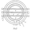
- a heating unit consisting of a circular tray 1 having a layer 2 of thermally-insulative material, such as microporous material, disposed therein and a peripheral thermally-insulative wall 3, within which four infra-red lamps, one shown at 4, are supported.
- Each lamp 4 consists of tungsten filament 5 supported within a tubular quartz envelope 6, and each end of each lamp 4 is formed with a pinch seal (not shown), having a connection between the respective end of the filament 5 and an electrical connector sealed therein, each pinch seal being housed within a ceramic end cap, such as at 7.
- the tray 1 also includes an inner thermally-insulative wall 8, which is concentric with the peripheral wall 3 and of such a diameter as to enclose the entire length of all of the filaments 5 within the lamps 4.
- the heating unit is preferably mounted beneath, and urged up towards, a glass ceramic plate 19, by a suitable mounting arrangement 20, to form a hotplate of a cooking hob.
- the mounting arrangement 20 is fixed to a base 21 of a housing for the cooking hob.
- the four lamp filaments 5 and the two elements 9 and 10 may be energised independently and/or concurrently, so that only the central hotplate region within the inner wall or alternatively the whole region may be heated. Furthermore, any combination of one or more lamps and one or both elements may be energised to provide various discrete power outputs, and thus temperature settings, whilst maintaining an aesthetically pleasing balanced effect of the lamps, as seen through the glass ceramic plate.
- a thermal limiter (not shown) either mechanical or electronic, is also employed within the heating apparatus to limit the operating temperature of the apparatus to prevent damage to the glass ceramic by overheating. It may be preferable for the limiter to control the heating elements 9 and 10 only, so that tripping of the limiter would not be so conspicuous, as only the elements, and not the lamps, would be de-energised if overheating occurred.
- switching of the lamp filaments into various series and/or parallel configurations provides relatively high power outputs and that energisation of one or both of the heating elements 9 and 10 provides lower power outputs.
- Figure 2 wherein like parts are labelled with like reference numerals with respect to Figure 1, shows an alternative embodiment to that shown in Figure 1, wherein only three lamps, such as at 4, are provided in combination with only one heating element 9.
- Such an arrangement may be advantageous in that one lamp has been replaced by a conventional heating element, thereby providing a cost saving in manufacture of the apparatus.
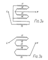
- Figures 3a and 3b show the configurations of four lamp filaments 11 to 14 required to generate the third lowest and the lowest power outputs of the apparatus.
- the remaining configurations for the power outputs provided are shown in the above-mentioned U.K. Patent Application No.GB-A-2 132 060, wherein the configurations giving the same power outputs as those shown in Figures 3a and 3b also include one or more diodes to generate the required power output.
- the present configurations shown in Figures 3a and 3b overcome this disadvantage by including an additional element 15 in series with the configuration formed by lamp filaments 11 to 14, which, when switched into the two configurations generates the same respective power outputs as when diodes are used.
- the element 15 may be either a fifth lamp filament or a conventional heating element as shown in Figures 1 and 2.
- a further use of the additional element 15 may be as a pre-heating device to produce faster warm-up periods of the apparatus.
- the use of the element 15 would provide a high power output fur an initial warm-up period, the length of which could be controlled by a timer and/or a thermal sensor device.
- the element 15 could also be used at various times during energisation of the lamp filaments 11 to 14, but preferably not continuously. Subsequent use of the element 15 after the initial warm-up period could be controlled manually.
- the initial warm-up period could be controlled by any suitable type of timing device, so that the element 15 is de-energised at the end of a predetermined time, such as 6 mins. for example.
- the initial warm-up period could be controlled by any suitable thermal device, including a pre-set thermostat disposed at any suitable location within the apparatus to cause de-energisation of element 15 when a certain operating temperature is attained.
- a pre-heating element 15 may be that power outputs exceeding the limit that the glass ceramic is capable of withstanding may be utilised, because it is only energised until the required operating temperature is attained, and additionally at lower outputs, a thermal limiter to protect the glass ceramic may not be required, as the glass ceramic should not exceed its limit at these lower outputs. This therefore may provide an additional cost saving.
- the timer and/or thermal device controlling the pre-heating element 15 may be necessary to cause the timer and/or thermal device controlling the pre-heating element 15 to by-pass the limiter, at least while the element 15 is initially energised, to prevent nuisance tripping of the limiter.
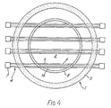
- FIGs 4 and 5 wherein like parts are also labelled with like reference numerals with respect to Figures 1 and 2, show two alternative embodiments which include an additional filament accommodated within each lamp, instead of a conventional heating element.
- Each lamp as at 4 shown in Figure 4 accommodates a filament 5, the length of which is commensurate with the area of the inner hotplate region within the wall 8, and a second filament 16, the length uf which is commensurate with the area of the whole hotplate region within the outer wall 3.
- the two filaments may be energised independently and/or concurrently as required.
- the embodiment shown in Figure 5 is provided with a non-central inner hotplate region within the inner wall 8, which is integral around part of its circumference with the outer wall 3.
- a lamp filament 18 is accommodated within each lamp 4, having a length commensurate with the area of the whole hotplate region.
- each filament 18 is tapped at a point 19 along its length, so that, if required only the filament length coinciding with the area of the inner hotplate region may be energised.
- Filament 18 thus effectively consists of a filament 22 commensurate the inner hotplate region and an extended portion 23 thereof commensurate with the whole hotplate region.
- inventions shown in Figures 4 and 5 may be advantageous in providing an increased number of switching combinations of the filaments, especially if they are maintained at a 100% output, as well as being cost-effective, because two filaments are accommodated within only one lamp.
- each lamp is provided with an infra-red-reflective coating applied to the lower half of the quartz envelope, to reflect radiation emitted downwardly from the filaments back in an upwards direction towards the glass ceramic plate.
- infra-red reflector between the lamps and the layer 2 of thermally-insulative material, which may be cost-effective and easier to manufacture.
Landscapes
- Chemical & Material Sciences (AREA)
- Engineering & Computer Science (AREA)
- Ceramic Engineering (AREA)
- Resistance Heating (AREA)
- Electric Stoves And Ranges (AREA)
- Control Of Throttle Valves Provided In The Intake System Or In The Exhaust System (AREA)
- Cookers (AREA)
- Yarns And Mechanical Finishing Of Yarns Or Ropes (AREA)
- General Preparation And Processing Of Foods (AREA)
- Central Heating Systems (AREA)
- Air-Conditioning For Vehicles (AREA)
Priority Applications (1)
| Application Number | Priority Date | Filing Date | Title |
|---|---|---|---|
| AT88200915T ATE79498T1 (de) | 1984-05-15 | 1985-05-10 | Heizgeraet. |
Applications Claiming Priority (2)
| Application Number | Priority Date | Filing Date | Title |
|---|---|---|---|
| GB8412339 | 1984-05-15 | ||
| GB848412339A GB8412339D0 (en) | 1984-05-15 | 1984-05-15 | Heating apparatus |
Related Parent Applications (1)
| Application Number | Title | Priority Date | Filing Date |
|---|---|---|---|
| EP85303318.1 Division | 1985-05-10 |
Publications (2)
| Publication Number | Publication Date |
|---|---|
| EP0302535A1 EP0302535A1 (en) | 1989-02-08 |
| EP0302535B1 true EP0302535B1 (en) | 1992-08-12 |
Family
ID=10560963
Family Applications (2)
| Application Number | Title | Priority Date | Filing Date |
|---|---|---|---|
| EP88200915A Expired - Lifetime EP0302535B1 (en) | 1984-05-15 | 1985-05-10 | Heating apparatus |
| EP85303318A Expired EP0164900B1 (en) | 1984-05-15 | 1985-05-10 | Heating apparatus |
Family Applications After (1)
| Application Number | Title | Priority Date | Filing Date |
|---|---|---|---|
| EP85303318A Expired EP0164900B1 (en) | 1984-05-15 | 1985-05-10 | Heating apparatus |
Country Status (7)
| Country | Link |
|---|---|
| US (2) | US4639579A (enExample) |
| EP (2) | EP0302535B1 (enExample) |
| AT (2) | ATE79498T1 (enExample) |
| AU (2) | AU569156B2 (enExample) |
| CA (1) | CA1250879A (enExample) |
| DE (2) | DE3586504T2 (enExample) |
| GB (1) | GB8412339D0 (enExample) |
Families Citing this family (32)
| Publication number | Priority date | Publication date | Assignee | Title |
|---|---|---|---|---|
| DE3406604C1 (de) * | 1984-02-23 | 1985-07-25 | Bosch-Siemens Hausgeräte GmbH, 7000 Stuttgart | Heizeinrichtung fuer Strahlungsheizstellen mit elektrischen Strahlungsheizelementen |
| DE3503648C2 (de) * | 1984-09-22 | 1994-08-11 | Ego Elektro Blanc & Fischer | Strahlheizkörper für Kochgeräte |
| USD313466S (en) | 1985-06-11 | 1991-01-01 | Micropore International Ltd. | Infra-red heater |
| GB8514785D0 (en) * | 1985-06-11 | 1985-07-10 | Micropore International Ltd | Infra-red heaters |
| JPS62271386A (ja) * | 1986-01-04 | 1987-11-25 | カ−ル・ツワイス・ステイフツング | ガラス−セラミツク系調理用レンジ |
| GB8602507D0 (en) * | 1986-02-01 | 1986-03-05 | Micropore International Ltd | Electric radiation heater |
| DE3622415A1 (de) * | 1986-07-03 | 1988-01-07 | Ego Elektro Blanc & Fischer | Strahlheizkoerper |
| GB8704469D0 (en) * | 1987-02-25 | 1987-04-01 | Thorn Emi Appliances | Thick film electrically resistive tracks |
| DE3737475A1 (de) * | 1987-11-05 | 1989-05-18 | Ego Elektro Blanc & Fischer | Strahlheizkoerper fuer kochgeraete |
| FI890837A7 (fi) * | 1988-02-26 | 1989-08-27 | Electrolux Ltd | Säädettävä sähkölämmitin |
| USD326907S (en) | 1988-09-29 | 1992-06-09 | Ceramaspeed Limited | Radiant stove heater |
| DE3840360A1 (de) * | 1988-11-30 | 1990-05-31 | Ego Elektro Blanc & Fischer | Strahlungs-heizkoerper |
| DE3903978A1 (de) * | 1989-02-10 | 1990-08-16 | Imp Werke Gmbh | Lichtkochstelle mit mindestens zwei infrarotroehren |
| DE3904177A1 (de) * | 1989-02-11 | 1990-08-16 | Ego Elektro Blanc & Fischer | Elektrischer strahlheizkoerper |
| USD330661S (en) | 1989-02-14 | 1992-11-03 | Ceramaspeed Limited | Stove top heating element |
| DE3908600C2 (de) * | 1989-03-16 | 1997-01-30 | Ako Werke Gmbh & Co | Strahlungsheizeinrichtung |
| DE3908599A1 (de) * | 1989-03-16 | 1990-09-20 | Ako Werke Gmbh & Co | Strahlungsheizeinrichtung |
| GB8924936D0 (en) * | 1989-11-04 | 1989-12-28 | Ceramaspeed Ltd | Radiant electric heaters |
| DE3938437A1 (de) * | 1989-11-20 | 1991-05-23 | Heraeus Quarzglas | Infrarot-strahler |
| GB8926289D0 (en) * | 1989-11-21 | 1990-01-10 | Ceramaspeed Ltd | Radiant electric heaters |
| DE3942900A1 (de) * | 1989-12-23 | 1991-06-27 | Miele & Cie | Kochstelle fuer elektroherde |
| DE4022844C1 (enExample) * | 1990-07-18 | 1992-02-27 | Schott Glaswerke, 6500 Mainz, De | |
| DE4022846C2 (de) * | 1990-07-18 | 1994-08-11 | Schott Glaswerke | Vorrichtung zur Leistungssteuerung und -begrenzung bei einer Heizfläche aus Glaskeramik oder einem vergleichbaren Material |
| GB2263379B (en) * | 1992-01-10 | 1995-07-26 | Ceramaspeed Ltd | Radiant heater having multiple heating zones |
| GB9310514D0 (en) * | 1993-05-21 | 1993-07-07 | Ceramaspeed Ltd | Radiant electric heater |
| GB2287388B (en) * | 1994-03-09 | 1997-07-16 | Ceramaspeed Ltd | Radiant electric heater |
| US5790752A (en) * | 1995-12-20 | 1998-08-04 | Hytec Flow Systems | Efficient in-line fluid heater |
| GB2336985A (en) * | 1998-04-30 | 1999-11-03 | Ceramaspeed Ltd | A radiant electric heater having both a lamp-form heating element and a ribbon heating element |
| US7825353B2 (en) | 2005-10-05 | 2010-11-02 | Evo, Inc. | Electric cooking apparatus |
| US7783176B2 (en) * | 2007-06-28 | 2010-08-24 | Strix Limited | Heaters for liquid heating vessels |
| EP2315493B1 (de) * | 2009-10-21 | 2017-05-10 | Mahle Behr France Rouffach S.A.S | Heizeinrichtung insbesondere für eine Kraftfahrzeugklimaanlage |
| CN110079786A (zh) * | 2019-06-03 | 2019-08-02 | 杭州睿清环保科技有限公司 | 用于制备大面积金刚石薄膜的热壁热丝cvd的装置 |
Citations (6)
| Publication number | Priority date | Publication date | Assignee | Title |
|---|---|---|---|---|
| GB1273023A (en) * | 1969-02-18 | 1972-05-03 | Electricity Council | Improvements in or relating to electric cookers |
| DE2809131A1 (de) * | 1978-03-03 | 1979-09-13 | Ako Werke Gmbh & Co | Elektrische kochplatte |
| GB2044057A (en) * | 1979-02-07 | 1980-10-08 | Micropore International Ltd | Smooth top cookers |
| EP0037638A1 (en) * | 1980-03-05 | 1981-10-14 | Kenwood Manufacturing Company Limited | Cooking apparatus |
| GB2092869A (en) * | 1981-02-10 | 1982-08-18 | Micropore International Ltd | An electric cooker |
| GB2132060A (en) * | 1982-12-24 | 1984-06-27 | Thorn Emi Domestic Appliances | Heating apparatus |
Family Cites Families (18)
| Publication number | Priority date | Publication date | Assignee | Title |
|---|---|---|---|---|
| GB191223748A (en) * | 1912-10-17 | 1913-10-17 | Georges Edmond Dutertre | Glow Lamp Radiator for Cooking or other Heating Purposes. |
| US2600605A (en) * | 1948-11-18 | 1952-06-17 | Christian B Backer | Multiple coil tubular heating element |
| CH287511A (fr) * | 1949-11-17 | 1952-12-15 | Backer Christian Bergh | Elément de chauffage électrique. |
| GB735064A (en) * | 1951-10-20 | 1955-08-10 | Sylvania Electric Prod | Electric incandescent lamp |
| US2988634A (en) * | 1958-02-05 | 1961-06-13 | William J Miskella | Holder for elongated infrared heating lamp |
| US3219872A (en) * | 1962-09-19 | 1965-11-23 | Gen Electric | Radiant energy device |
| US3443144A (en) * | 1964-12-31 | 1969-05-06 | Sylvania Electric Prod | Infrared incandescent lamp |
| US3375346A (en) * | 1965-09-22 | 1968-03-26 | Gen Motors Corp | Infrared surface heating unit with two filaments |
| US3330939A (en) * | 1965-09-22 | 1967-07-11 | Gen Motors Corp | Electric hot plate |
| US3355574A (en) * | 1965-10-01 | 1967-11-28 | Gen Motors Corp | Electrical surface heater with plural lamps |
| US3579021A (en) * | 1969-04-30 | 1971-05-18 | Sylvania Electric Prod | Incandescent lamp having linear output |
| US3663798A (en) * | 1969-08-25 | 1972-05-16 | Thermo Electron Corp | An infrared heating surface |
| US3714885A (en) * | 1971-10-15 | 1973-02-06 | F S Mfg Co | Broiler-grill cooking appliance |
| US3912905A (en) * | 1974-02-25 | 1975-10-14 | Kanthal Corp | Electric resistance heating device |
| NZ196104A (en) * | 1980-02-01 | 1984-08-24 | Micropore International Ltd | Cooker plate with twin element:thermal cut-out for one |
| ZA813746B (en) * | 1980-07-22 | 1982-07-28 | Micropore International Ltd | Electric radiant heater unit for a glass ceramic top cooker |
| DE8133341U1 (de) * | 1980-11-17 | 1982-03-25 | Micropore International Ltd., Droitwich, Worcestershire | Elektrischer strahlungsheizer fuer herde mit glaskeramikdeckplatten |
| DE3406604C1 (de) * | 1984-02-23 | 1985-07-25 | Bosch-Siemens Hausgeräte GmbH, 7000 Stuttgart | Heizeinrichtung fuer Strahlungsheizstellen mit elektrischen Strahlungsheizelementen |
-
1984
- 1984-05-15 GB GB848412339A patent/GB8412339D0/en active Pending
-
1985
- 1985-05-10 EP EP88200915A patent/EP0302535B1/en not_active Expired - Lifetime
- 1985-05-10 DE DE8888200915T patent/DE3586504T2/de not_active Expired - Fee Related
- 1985-05-10 EP EP85303318A patent/EP0164900B1/en not_active Expired
- 1985-05-10 AT AT88200915T patent/ATE79498T1/de active
- 1985-05-10 DE DE8585303318T patent/DE3568930D1/de not_active Expired
- 1985-05-10 AT AT85303318T patent/ATE41580T1/de active
- 1985-05-13 CA CA000481412A patent/CA1250879A/en not_active Expired
- 1985-05-14 US US06/733,802 patent/US4639579A/en not_active Expired - Fee Related
- 1985-05-15 AU AU42501/85A patent/AU569156B2/en not_active Ceased
-
1986
- 1986-11-13 US US06/929,793 patent/US4707589A/en not_active Expired - Fee Related
-
1987
- 1987-12-02 AU AU82031/87A patent/AU602544B2/en not_active Ceased
Patent Citations (9)
| Publication number | Priority date | Publication date | Assignee | Title |
|---|---|---|---|---|
| GB1273023A (en) * | 1969-02-18 | 1972-05-03 | Electricity Council | Improvements in or relating to electric cookers |
| DE2809131A1 (de) * | 1978-03-03 | 1979-09-13 | Ako Werke Gmbh & Co | Elektrische kochplatte |
| GB2044057A (en) * | 1979-02-07 | 1980-10-08 | Micropore International Ltd | Smooth top cookers |
| EP0037638A1 (en) * | 1980-03-05 | 1981-10-14 | Kenwood Manufacturing Company Limited | Cooking apparatus |
| GB2092869A (en) * | 1981-02-10 | 1982-08-18 | Micropore International Ltd | An electric cooker |
| GB2132060A (en) * | 1982-12-24 | 1984-06-27 | Thorn Emi Domestic Appliances | Heating apparatus |
| EP0117346A2 (en) * | 1982-12-24 | 1984-09-05 | THORN EMI Patents Limited | Heating apparatus |
| EP0132888A1 (en) * | 1982-12-24 | 1985-02-13 | THORN EMI Appliances Limited | Heating apparatus |
| EP0149267A2 (en) * | 1982-12-24 | 1985-07-24 | THORN EMI Patents Limited | Heating apparatus |
Also Published As
| Publication number | Publication date |
|---|---|
| AU4250185A (en) | 1985-11-21 |
| DE3586504D1 (de) | 1992-09-17 |
| AU602544B2 (en) | 1990-10-18 |
| ATE41580T1 (de) | 1989-04-15 |
| AU569156B2 (en) | 1988-01-21 |
| CA1251821C (enExample) | 1989-03-28 |
| US4707589A (en) | 1987-11-17 |
| DE3586504T2 (de) | 1993-03-18 |
| ATE79498T1 (de) | 1992-08-15 |
| EP0164900A1 (en) | 1985-12-18 |
| DE3568930D1 (en) | 1989-04-20 |
| AU8203187A (en) | 1988-03-24 |
| GB8412339D0 (en) | 1984-06-20 |
| EP0164900B1 (en) | 1989-03-15 |
| US4639579A (en) | 1987-01-27 |
| EP0302535A1 (en) | 1989-02-08 |
| CA1250879A (en) | 1989-03-07 |
Similar Documents
| Publication | Publication Date | Title |
|---|---|---|
| EP0302535B1 (en) | Heating apparatus | |
| US4789772A (en) | Infra-red heaters | |
| EP0551172B1 (en) | Radiant heater having multiple heating zones | |
| US4868371A (en) | Heating assembly using tungsten-halogen lamps | |
| US5171973A (en) | Radiant electric heaters | |
| JPH081826B2 (ja) | 料理器具用ラジアントヒータ | |
| US4508961A (en) | Electric radiant heater units for glass ceramic top cookers | |
| US5049726A (en) | Radiant electric heaters | |
| EP0174774A1 (en) | Heating apparatus | |
| US5517002A (en) | Radiant electric heater | |
| EP0774881B1 (en) | Infra-red heater arrangement | |
| CA1251821A (en) | Heating apparatus | |
| GB2170665A (en) | Heating apparatus | |
| GB2153555A (en) | Temperature control of heating apparatus | |
| EP0892584A2 (en) | Electric heater assembly for cooking range | |
| JP2604026B2 (ja) | 電気調理器 | |
| JP2603054B2 (ja) | 電気調理器 | |
| KR930004202B1 (ko) | 전기 조리기 | |
| GB2257002A (en) | Ceramic electric hob | |
| GB2324692A (en) | IR heating lamp having different heating output zones |
Legal Events
| Date | Code | Title | Description |
|---|---|---|---|
| PUAI | Public reference made under article 153(3) epc to a published international application that has entered the european phase |
Free format text: ORIGINAL CODE: 0009012 |
|
| AC | Divisional application: reference to earlier application |
Ref document number: 164900 Country of ref document: EP |
|
| AK | Designated contracting states |
Kind code of ref document: A1 Designated state(s): AT BE CH DE FR GB IT LI LU NL SE |
|
| 17P | Request for examination filed |
Effective date: 19890810 |
|
| 17Q | First examination report despatched |
Effective date: 19911008 |
|
| GRAA | (expected) grant |
Free format text: ORIGINAL CODE: 0009210 |
|
| AC | Divisional application: reference to earlier application |
Ref document number: 164900 Country of ref document: EP |
|
| AK | Designated contracting states |
Kind code of ref document: B1 Designated state(s): AT BE CH DE FR GB IT LI LU NL SE |
|
| REF | Corresponds to: |
Ref document number: 79498 Country of ref document: AT Date of ref document: 19920815 Kind code of ref document: T |
|
| ITF | It: translation for a ep patent filed | ||
| ET | Fr: translation filed | ||
| REF | Corresponds to: |
Ref document number: 3586504 Country of ref document: DE Date of ref document: 19920917 |
|
| PG25 | Lapsed in a contracting state [announced via postgrant information from national office to epo] |
Ref country code: GB Effective date: 19930510 Ref country code: AT Effective date: 19930510 |
|
| PG25 | Lapsed in a contracting state [announced via postgrant information from national office to epo] |
Ref country code: SE Effective date: 19930511 |
|
| PG25 | Lapsed in a contracting state [announced via postgrant information from national office to epo] |
Ref country code: LU Free format text: LAPSE BECAUSE OF NON-PAYMENT OF DUE FEES Effective date: 19930531 Ref country code: LI Effective date: 19930531 Ref country code: CH Effective date: 19930531 Ref country code: BE Effective date: 19930531 |
|
| PLBE | No opposition filed within time limit |
Free format text: ORIGINAL CODE: 0009261 |
|
| STAA | Information on the status of an ep patent application or granted ep patent |
Free format text: STATUS: NO OPPOSITION FILED WITHIN TIME LIMIT |
|
| 26N | No opposition filed | ||
| BERE | Be: lapsed |
Owner name: THORN EMI PATENTS LTD Effective date: 19930531 |
|
| PG25 | Lapsed in a contracting state [announced via postgrant information from national office to epo] |
Ref country code: NL Effective date: 19931201 |
|
| GBPC | Gb: european patent ceased through non-payment of renewal fee |
Effective date: 19930510 |
|
| NLV4 | Nl: lapsed or anulled due to non-payment of the annual fee | ||
| PG25 | Lapsed in a contracting state [announced via postgrant information from national office to epo] |
Ref country code: FR Effective date: 19940131 |
|
| REG | Reference to a national code |
Ref country code: CH Ref legal event code: PL |
|
| PG25 | Lapsed in a contracting state [announced via postgrant information from national office to epo] |
Ref country code: DE Effective date: 19940201 |
|
| REG | Reference to a national code |
Ref country code: FR Ref legal event code: ST |
|
| EUG | Se: european patent has lapsed |
Ref document number: 88200915.2 Effective date: 19931210 |