EP0302355B1 - Fe-base soft magnetic alloy powder and magnetic core thereof and method of producing same - Google Patents
Fe-base soft magnetic alloy powder and magnetic core thereof and method of producing same Download PDFInfo
- Publication number
- EP0302355B1 EP0302355B1 EP88111982A EP88111982A EP0302355B1 EP 0302355 B1 EP0302355 B1 EP 0302355B1 EP 88111982 A EP88111982 A EP 88111982A EP 88111982 A EP88111982 A EP 88111982A EP 0302355 B1 EP0302355 B1 EP 0302355B1
- Authority
- EP
- European Patent Office
- Prior art keywords
- alloy
- powder
- soft magnetic
- amorphous alloy
- amorphous
- Prior art date
- Legal status (The legal status is an assumption and is not a legal conclusion. Google has not performed a legal analysis and makes no representation as to the accuracy of the status listed.)
- Expired - Lifetime
Links
Images


Classifications
-
- H—ELECTRICITY
- H01—ELECTRIC ELEMENTS
- H01F—MAGNETS; INDUCTANCES; TRANSFORMERS; SELECTION OF MATERIALS FOR THEIR MAGNETIC PROPERTIES
- H01F1/00—Magnets or magnetic bodies characterised by the magnetic materials therefor; Selection of materials for their magnetic properties
- H01F1/01—Magnets or magnetic bodies characterised by the magnetic materials therefor; Selection of materials for their magnetic properties of inorganic materials
- H01F1/03—Magnets or magnetic bodies characterised by the magnetic materials therefor; Selection of materials for their magnetic properties of inorganic materials characterised by their coercivity
- H01F1/032—Magnets or magnetic bodies characterised by the magnetic materials therefor; Selection of materials for their magnetic properties of inorganic materials characterised by their coercivity of hard-magnetic materials
-
- H—ELECTRICITY
- H01—ELECTRIC ELEMENTS
- H01F—MAGNETS; INDUCTANCES; TRANSFORMERS; SELECTION OF MATERIALS FOR THEIR MAGNETIC PROPERTIES
- H01F1/00—Magnets or magnetic bodies characterised by the magnetic materials therefor; Selection of materials for their magnetic properties
- H01F1/01—Magnets or magnetic bodies characterised by the magnetic materials therefor; Selection of materials for their magnetic properties of inorganic materials
- H01F1/03—Magnets or magnetic bodies characterised by the magnetic materials therefor; Selection of materials for their magnetic properties of inorganic materials characterised by their coercivity
- H01F1/12—Magnets or magnetic bodies characterised by the magnetic materials therefor; Selection of materials for their magnetic properties of inorganic materials characterised by their coercivity of soft-magnetic materials
- H01F1/14—Magnets or magnetic bodies characterised by the magnetic materials therefor; Selection of materials for their magnetic properties of inorganic materials characterised by their coercivity of soft-magnetic materials metals or alloys
- H01F1/147—Alloys characterised by their composition
- H01F1/153—Amorphous metallic alloys, e.g. glassy metals
- H01F1/15341—Preparation processes therefor
- H01F1/1535—Preparation processes therefor by powder metallurgy, e.g. spark erosion
-
- H—ELECTRICITY
- H01—ELECTRIC ELEMENTS
- H01F—MAGNETS; INDUCTANCES; TRANSFORMERS; SELECTION OF MATERIALS FOR THEIR MAGNETIC PROPERTIES
- H01F1/00—Magnets or magnetic bodies characterised by the magnetic materials therefor; Selection of materials for their magnetic properties
- H01F1/01—Magnets or magnetic bodies characterised by the magnetic materials therefor; Selection of materials for their magnetic properties of inorganic materials
- H01F1/03—Magnets or magnetic bodies characterised by the magnetic materials therefor; Selection of materials for their magnetic properties of inorganic materials characterised by their coercivity
- H01F1/12—Magnets or magnetic bodies characterised by the magnetic materials therefor; Selection of materials for their magnetic properties of inorganic materials characterised by their coercivity of soft-magnetic materials
- H01F1/14—Magnets or magnetic bodies characterised by the magnetic materials therefor; Selection of materials for their magnetic properties of inorganic materials characterised by their coercivity of soft-magnetic materials metals or alloys
- H01F1/147—Alloys characterised by their composition
- H01F1/153—Amorphous metallic alloys, e.g. glassy metals
- H01F1/15358—Making agglomerates therefrom, e.g. by pressing
- H01F1/15366—Making agglomerates therefrom, e.g. by pressing using a binder
-
- H—ELECTRICITY
- H01—ELECTRIC ELEMENTS
- H01F—MAGNETS; INDUCTANCES; TRANSFORMERS; SELECTION OF MATERIALS FOR THEIR MAGNETIC PROPERTIES
- H01F1/00—Magnets or magnetic bodies characterised by the magnetic materials therefor; Selection of materials for their magnetic properties
- H01F1/01—Magnets or magnetic bodies characterised by the magnetic materials therefor; Selection of materials for their magnetic properties of inorganic materials
- H01F1/03—Magnets or magnetic bodies characterised by the magnetic materials therefor; Selection of materials for their magnetic properties of inorganic materials characterised by their coercivity
- H01F1/12—Magnets or magnetic bodies characterised by the magnetic materials therefor; Selection of materials for their magnetic properties of inorganic materials characterised by their coercivity of soft-magnetic materials
- H01F1/14—Magnets or magnetic bodies characterised by the magnetic materials therefor; Selection of materials for their magnetic properties of inorganic materials characterised by their coercivity of soft-magnetic materials metals or alloys
- H01F1/20—Magnets or magnetic bodies characterised by the magnetic materials therefor; Selection of materials for their magnetic properties of inorganic materials characterised by their coercivity of soft-magnetic materials metals or alloys in the form of particles, e.g. powder
Definitions
- the present invention relates to Fe-base soft magnetic alloy powder having excellent magnetic properties and applications thereof, and more particularly to Fe-base soft magnetic alloy powder having a low magnetostriction, and applications thereof as transformers, choke coils, saturable reactors, etc. and methods of producing them.
- magnetic cores for transformers, motors, chokes, noise filters, etc. are made of crystalline materials such as Fe-Si alloys, Permalloy, ferrites, etc.
- Fe-Si alloys have large specific resistance and their crystal magnetic anisotropy is not zero. Accordingly, they suffer from large core losses at a relatively high frequency.
- Permalloy also has a high core loss at a high frequency.
- ferrites have small core losses at a high frequency
- their magnetic flux densities are at most 0.5 T. Accordingly, when they are operated at a large magnetic flux density, they are close to saturation, leading to large core losses.
- transformers operable at a high frequency such as those for switching regulators are required to be miniaturized.
- the magnetic flux density in an operating region should be increased.
- the increase in a core loss of ferrites may become a serious problem for practical applications.
- dust cores of crystalline magnetic alloys are conventionally used.
- the dust cores are prepared by forming fine powder of the magnetic alloys and solidifying it via insulating layers. For such insulating layers, organic materials are used.
- Such magnetic dust cores are mainly used for chokes, noise filters, etc.
- the dust cores made of the conventional crystalline magnetic powder have small permeability, a large number of winding is necessary to achieve sufficient inductance, making it difficult to miniaturize magnetic cores constituted by such dust cores. In addition, since they have large core losses, a lot of heat is generated during their use.
- amorphous alloys are essentially composed of Fe, Co or Ni, etc. as a basic element, and at least one of P, C, B, Si, Al, Ge, etc. as a metalloid which can make the resulting alloys amorphous. Further, it is known that there are amorphous alloys composed of Fe, Co or Ni and Ti, Zr, Hf, Nb, etc. without metalloids, which can be produced by a roll method.
- amorphous magnetic alloys are tough and difficult to be pulverized, they are generally produced in the form of a thin ribbon and the thin ribbon is laminated or wound to form a magnetic core.
- a magnetic core from the thin ribbon, it should be formed into a toroidal wound core or cut into a desired shape such as a U-shape or an E-shape and then laminated.
- a U-shape or E-shape magnetic core is desired, its production is generally difficult.
- Amorphous alloys which may be used for such dust cores are mainly classified into two categories: iron-base alloys and cobalt-base alloys.
- Fe-base amorphous alloys are advantageous in that they are less expensive than Co-base amorphous alloys, but they generally have larger core loss and lower permeability at high frequency than the Co-base amorphous alloys.
- the Co-base amorphous alloys have small core loss and high permeability at high frequency, their core loss and permeability vary largely as the time passes, posing problems in practical use. Further, since they contain as a main component an expensive cobalt, they are inevitably disadvantageous in terms of cost.
- alloy powder and dust cores having sufficiently high saturation magnetic flux density and other good magnetic properties cannot be obtained from Fe-base or Co-base amorphous alloys.
- An Fe-base soft magnetic alloy powder according to the first part of claim 1 is described in EP-A-0271657.
- an object of the present invention is to provide an Fe-base soft magnetic alloy powder having excellent magnetic characteristics such as a saturation magnetic flux density, etc.
- Another object of the present invention is to provide a method of producing such Fe-base soft magnetic alloy powder.
- a further object of the present invention is to provide an Fe-base soft magnetic alloy dust core having excellent soft magnetic properties, particularly a high saturation magnetic flux density, a small core loss and a small change of core loss with time, large permeability and other excellent magnetic properties.
- a further object of the present invention is to provide a method of producing such an Fe-base soft magnetic alloy dust core.
- the Fe-base soft magnetic alloy powder according to the present invention has the composition represented by the general formula: (Fe 1-a M a ) 100-x-y-z- ⁇ - ⁇ - ⁇ Cu x Si y B z M' ⁇ M'' ⁇ X ⁇ wherein M is Co and/or Ni, M' is at least one element selected from the group consisting of Nb, W, Ta, Zr, Hf, Ti and Mo, M'' is at least one element selected from the group consisting of V, Cr, Mn, Al, elements in the platinum group, Sc, Y, rare earth elements, Au, Zn, Sn and Re, X is at least one element selected from the group consisting of C, Ge, P, Ga, Sb, In, Be and As, and a, x, y, z, ⁇ , ⁇ and ⁇ respectively satisfy 0 ⁇ a ⁇ 0.5, 0.1 ⁇ x ⁇ 3, 0 ⁇ y ⁇ 30, 0 ⁇ z ⁇ 25, 0 ⁇ y+z ⁇ 35, 0.1 ⁇ 30 0
- the method of producing Fe-base soft magnetic alloy powder according to the present invention comprises the steps of rapidly quenching a melt of the above composition and heat-treating it to generate fine crystalline particles having an average particle size of 50 nm or less which constitute at least 50% of the alloy structure.
- the Fe-base soft magnetic alloy dust core according to the present invention is composed of compressed Fe-base soft magnetic alloy powder.
- the method of producing an Fe-base soft magnetic alloy dust core which comprises compressing fine powder of the Fe-base soft magnetic alloy together with a binder and/or an electrically insulating material.
- Fe may be substituted by Co and/or Ni in the range from 0 to less than 0.5.
- the content of Co and/or Ni which is represented by "a" is preferably 0-0.3.
- Cu is an indispensable element, and its content "x" is 0.1-3 atomic %.
- x is 0.1-3 atomic %.
- it is less than 0.1 atomic %, substantially no effect on the reduction of a core loss and on the increase in permeability can be obtained by the addition of Cu.
- it exceeds 3 atomic % the alloy's core loss becomes larger than those containing no Cu, reducing the permeability, too.
- the preferred content of Cu in the present invention is 0.5-2 atomic %, in which range the core loss is particularly small and the permeability is high.
- the crystalline particles are made fine, and this phenomenon is accelerated by the inclusion of Nb, Ta, W, Mo, Zr, Hf, Ti, etc.
- the crystalline particles are not fully made fine and thus the soft magnetic properties of the resulting alloy are poor.
- Nb and Mo are effective, and particularly Nb acts to keep the crystalline particles fine, thereby providing excellent soft magnetic properties.
- the Fe-base soft magnetic alloy has smaller magnetostriction than Fe-base amorphous alloys, which means that the Fe-base soft magnetic alloy has smaller magnetic anisotropy due to internal stress-strain, resulting in improved soft magnetic properties.
- the crystalline particles are unlikely to be made fine. Instead, a compound phase is likely to be formed and crystallized, thereby deteriorating the magnetic properties.
- Si and B are elements particularly for making fine the alloy structure.
- the Fe-base soft magnetic alloy is desirably produced by once forming an amorphous alloy with the addition of Si and B, and then forming fine crystalline particles by heat treatment.
- the content of Si ("y”) and that of B ("z") are 0 ⁇ y ⁇ 30 atomic %, 0 ⁇ z ⁇ 25 atomic %, and 0 ⁇ y+z ⁇ 35 atomic %, because the alloy would have an extremely reduced saturation magnetic flux density if otherwise.
- y+z should be 10-35 atomic % to facilitate the production of an amorphous alloy.
- the preferred range of y is 10-25 atomic %, and the preferred range of z is 3-12 atomic %, and the preferred range of y+z is 18-28 atomic %. In these ranges, the Fe-base soft magnetic alloy is provided with a low core loss.
- M′ acts when added together with Cu to make the precipitated crystalline particles fine.
- M′ is at least one element selected from the group consisting of Nb, W, Ta, Zr, Hf, Ti and Mo. These elements have a function of elevating the crystallization temperature of the alloy, and synergistically with Cu having a function of forming clusters and thus lowering the crystallization temperature, it suppresses the growth of the precipitated crystalline particles, thereby making them fine.
- the content of M′ ( ⁇ ) is 0.1-30 atomic %. When it is less than 0.1 atomic %, sufficient effect of making crystalline particles fine cannot be obtained, and when it exceeds 30 atomic % an extreme decrease in a saturation magnetic flux density ensues.
- the preferred content of M′ is 2-8 atomic %, in which range particularly excellent soft magnetic properties are obtained.
- most preferable as M′ is Nb and/or Mo, and particularly Nb in terms of magnetic properties.
- the addition of M′ provides the Fe-base soft magnetic alloy with as high permeability as that of the Co-base high-permeability materials.
- M ⁇ which is at least one element selected from the group consisting of V, Cr, Mn, Al, elements in the platinum group, Sc, Y, rare earth elements, Au, Zn, Sn and Re, may be added for the purposes of improving corrosion resistance and magnetic properties and of adjusting magnetostriction, but its content is at most 10 atomic %. When the content of M ⁇ exceeds 10 atomic %, an extremely decrease in a saturation magnetic flux density ensues. A particularly preferred amount of M ⁇ is 8 atomic % or less.
- At least one element selected from the group consisting of Ru, Rh, Pd, Os, Ir, Pt, Au, Cr and V is capable of providing the alloy with particularly excellent corrosion resistance and wear resistance.
- the alloy of the present invention may contain 10 atomic % or less of at least one element X selected from the group consisting of C, Ge, P, Ga, Sb, In, Be, As. These elements are effective for making amorphous, and when added with Si and B, they help make the alloy amorphous and also are effective for adjusting the magnetostriction and Curie temperature of the alloy.
- the preferred amount of X is 5 atomic % or less.
- the general ranges of a, x, y, z, ⁇ , ⁇ and ⁇ are 0 ⁇ a ⁇ 0.5 0.1 ⁇ x ⁇ 3 0 ⁇ y ⁇ 30 0 ⁇ z ⁇ 25 0 ⁇ y+z ⁇ 35 0.1 ⁇ 30 0 ⁇ 10 0 ⁇ 10, and the preferred ranges are 0 ⁇ a ⁇ 0.3 0.5 ⁇ x ⁇ 2 10 ⁇ y ⁇ 25 3 ⁇ z ⁇ 12 18 ⁇ y+z ⁇ 28 2 ⁇ 8 ⁇ 8 ⁇ 5.
- the alloy structure consists of fine crystalline particles.
- These crystalline particles are based on ⁇ -Fe having a bcc structure, in which Si and B, etc. are dissolved. These crystalline particles have an extremely small average particle size of 50 nm or less, and are uniformly distributed in the alloy structure.
- the average paticle size of the crystalline particles is determined by measuring the maximum size of each particle and averaging them. When the average particle size exceeds 50 nm, good soft magnetic properties are not obtained. It is preferably 20 nm or less and particularly 5 to 20 nm.
- the remaining portion of the alloy structure other than the fine crystalline particles is mainly amorphous. Even with fine crystalline particles occupying substantially 100% of the alloy structure, the Fe-base soft magnetic alloy of the present invention has sufficiently good magnetic properties.
- melt of the above composition is rapidly quenched by various methods.
- the first method comprises rapidly quenching an alloy melt having the above composition to provide amorphous alloy powder and then heat-treating the powder.
- the amorphous alloy powder can be produced by a water atomizing method, a gas atomizing method, a spray method, a cavitation method, a spark errosion method, a method of ejecting a melt into a rotating liquid, etc.
- the amorphous alloy powder is desirably completely amorphous, but it may contain a crystalline phase.
- the second method comprises rapidly quenching an alloy melt having the above composition to provide amorphous alloy ribbons, flakes or wires, heat-treating them to make them brittle, pulverizing them, and then heat-treating them to generate fine crystalline particles.
- the amorphous alloy ribbons, flakes or wires can be produced by a single roll method, a double roll method, a centrifugal quenching method, a method of spinning into a rotating liquid, etc.
- the first heat treatment is conducted at a temperature between a temperature which is lower than their crystallization temperatures by about 250 °C and their crystallization temperatures for a sufficient period of time for making them brittle, usually for 1-3 hours.
- the third method comprises rapidly quenching an alloy melt having the above composition to provide amorphous alloy ribbons, flakes or wires, causing them to absorb a hydrogen gas at a temperature lower than their crystallization temperatures for a sufficient period of time for making them brittle, pulverizing them to power, and then heat-treating the powder.
- the absorption of a hydrogen gas in the amorphous alloy ribbons, flakes or wires can be achieved by placing them in a pressurized hydrogen gas atmosphere, or by using them as a cathod in an electrolytic both for hydrogen production.
- the fourth method comprises rapidly quenching an alloy melt having the above composition to provide brittle amorphous alloy ribbons, flakes or wires, pulverizing them to amorphous alloy powder, and then heat-treating the powder.
- the brittle amorphous alloy ribbons, flakes or wires can be produced by reducing a cooling rate of the alloy melt, specifically, by slowing the rotation of a roll for quenching the alloy melt or by making the ribbons, flakes or wires thicker, etc.
- the fifth method comprises rapidly quenching an alloy melt having the above composition to provide amorphous alloy ribbons, flakes or wires, heat-treating them, and then pulverizing them to powder.
- amorphous alloy ribbons, flakes or wires are heat-treated at a temperature higher than their crystallization temperatures, they are made so brittle that they can easily be pulverized by a ball mill, a vibration mill, etc.
- the heat treatment is carried out by heating the amorphous alloy in the form of powder, ribbon, flake, wire, etc. in vacuum or in an inert gas atmosphere such as hydrogen, nitrogen, argon, etc.
- the temperature and time of the heat treatment vary depending upon the composition of the amorphous alloy ribbon and the shape and size of a magnetic core made from the amorphous alloy powder. In general, it is heated at a temperature higher than its crystallization temperature for a sufficient period of time for making it brittle. Specifically, it is preferably 450-700°C for 5 minutes to 24 hours. When the heat treatment temperature is lower than 450°C, crystallization is unlikely to take place with ease, requiring too much time for the heat treatment.
- the preferred heat treatment conditions are, taking into consideration practicality and uniform temperature control, etc., 500-650°C for 5 minutes to 6 hours.
- the alloy powder or the dust core is taken out of a heat treatment furnace and left to stand in the air or immersed in an oil, etc.
- the heat treatment atmosphere is preferably an inert gas atmosphere, but it may be an oxidizing atmosphere such as the air. Cooling may be carried out properly in the air or in a furnace. And the heat treatment may be conducted by a plurality of steps.
- the heat treatment can be carried out in a magnetic field to provide the alloy with magnetic anisotropy.
- the magnetic field need not be applied always during the heat treatment, and it is necessary only when the alloy is at a temperature lower than the Curie temperature Tc thereof.
- the alloy has an elevated Curie temperature because of crystallization than the amorphous counterpart, and so the heat treatment in a magnetic field can be carried out at temperatures higher than the Curie temperature of the corresponding amorphous alloy.
- the heat treatment in a magnetic field it may be carried out by two or more steps.
- a rotational magnetic field can be applied during the heat treatment.
- the Fe-base soft magnetic alloy of the present invention can be produced by other methods than liquid quenching methods, such as vapor deposition, ion plating, sputtering, etc.
- the Fe-base soft magnetic alloy powder according to the present invention may be in the form of a fine plate-like particle having a length less than 100 ⁇ m and a uniform thickness.
- the alloy powder having a particle size less than 5 mm (4 mesh) can be produced from the amorphous alloy ribbons and flakes in the methods 2 - 5. Such powder can be bonded with a resin to form electromagnetic wave-shielding sheets, etc.
- substantially sphere powder With respect to substantially sphere powder, it can be produced by a spark errosion method, by ejecting an alloy melt onto a rotating slanted disc to form sphere melt drops which are then thrown into a rotating water, or by ejecting an alloy melt into a rotating coolant.
- Such sphere powder usually has a particle size of 200 ⁇ m or less.
- the irregular powder particles With respect to powder of irregular shape, it can be produced by a water atomizing method, etc.
- the irregular powder particles usually have a maximum size of 2 mm or less.
- both sphere powder and irregular powder may be heat-treated under the conditions as described above.
- the Fe-base soft magnetic alloy powder heat-treated according to the present invention may be plated with Cu, Cr, Ni, Au, etc., or coated with SiO2, glass, an epoxy resin, etc. to improve its corrosion resistance or to form an insulating layer. Alternatively, it may be further heat-treated to form an oxide layer or a nitride layer thereon.
- the amorphous alloy powder as a starting material for the dust core may contain crystal phases, but the alloy structure is preferably amorphous to make sure the formation of uniform fine crystalline particles by a subsequent heat treatment.
- This amorphous alloy powder is compressed by a press, etc. to form a dust core.
- a binder such as a phenol resin, an epoxy resin, etc. is added. If a heat treatment is to be conducted after the compression process, a heat-resistant binder such as an inorganic varnish is desirable.
- the amorphous alloy powder is compressed at a temperature near its crystallization temperature for utilizing the deformation of the alloy by a viscous flow. Further a so-called explosion molding can be used to form a dust core.
- insulating layers are desirably provided among the powder particles to decrease the eddy current loss of the resulting dust core.
- the surface of the amorphous alloy powder is oxidized or coated with a water glass, metal alkoxide, ceramic ultra-fine powder, etc., and then the alloy powder is compressed.
- a heat treatment can be conducted on the amorphous alloy in the form of powder. However, except that the alloy has no magnetostriction, the heat treatment is desirably conducted after it is formed into a dust core.
- the heat treatment conditions are as described above.
- a melt having the composition (by atomic %) of 1% Cu, 16.5% Si, 6% B, 3% Nb and balance (73.5%) substantially Fe was formed into a ribbon of 5mm in width and 20 ⁇ m in thickness by a single roll method.
- the X-ray diffraction of this ribbon showed a halo pattern peculiar to an amorphous alloy as shown in Fig. 2(a).
- the amorphous alloy ribbon thus formed was heat-treated in a furnace filled with a nitrogen gas at 510 °C for 1 hour, cooled to room temperature and then pulverized by a vibration mill for 1 hour.
- the resulting powder was mostly composed of particles of 0.075 mm (200 mesh) or smaller.
- Fig. 2(b) shows an X-ray diffraction of the heat-treated powder
- Fig. 3 shows a transmission electron photomicrograph (magnification: 300,000) of the heat-treated powder. It was confirmed by the X-ray diffraction and the transmission electron photomicrograph that the heat-treated alloy powder had crystalline particles, and that the crystalline particles had a particle size of about 10 to 20 nm. The X-ray diffraction shows that the crystalline particles were composed of an Fe solid solution having a bcc structure in which Si, etc. were dissolved.
- this Fe-base soft magnetic alloy powder was measured with respect to magnetic properties by a vibration-type magnetometer (VSM).
- VSM vibration-type magnetometer
- An amorphous alloy ribbon having the composition of Fe 73.5 Cu1Nb3Si 17.5 B5 with a thickness of 30 ⁇ m and a width of 3 mm was produced by a double roll method, and it was heat-treated in a furnace filled with a nitrogen gas at 420 °C for 1 hour. After cooling down to room temperature, it was pulverized by a vibration mill for 2 hours. The resulting powder was mostly composed of particles of 0.075 mm (200 mesh) or smaller.
- the powder thus formed showed a halo pattern in an X-ray diffraction, which is peculiar to an amorphous alloy.
- the crystallization temperature of the alloy Powder was 495 °C when measured at a heating rate of 10 °C/min.
- this powder was heat-treated at 510°C for 1 hour in a furnace and then cooled to room temperature at a cooling rate of 5 °C/min.
- this powder was measured with respect to magnetic properties by a vibration-type magnetometer (VSM).
- VSM vibration-type magnetometer
- An amorphous alloy ribbon having the composition of Fe 71.5 Cu1Nb5Si 15.5 B7 with a thickness of 30 ⁇ m and a width of 15 mm was produced by a single roll method.
- the ribbon was brittle. It was pulverized by a ball mill for 5 hours.
- the resulting powder was mostly composed of particles of 2 mm (10 mesh) or smaller.
- the crystallization temperature of the alloy powder was 534 °C when measured at a heating rate of 10°C/min.
- this powder was heated to 570°C in an N2 gas atmosphere at a heating rate of 5°C/min, kept at 570°C for 1 hour and then cooled to room temperature at a cooling rate of 3°C/min.
- this powder was measured with respect to magnetic properties by a vibration-type magnetometer (VSM).
- VSM vibration-type magnetometer
- An alloy powder having the composition of Fe 73.5 Cu1 Nb3 Si 12.5 B10 was produced by a water atomizing method, and it was classified by a 0.042-mm (350-mesh) sieve.
- the powder thus formed showed a halo pattern in an X-ray diffraction, which is peculiar to an amorphous alloy.
- the crystallization temperature of the alloy powder was 500°C when measured at a heating rate of 10°C/min.
- this powder was heat-treated in an Ar gas atmosphere at 550°C for 1 hour and then rapidly cooled to room temperature in the air. It was observed by an X-ray diffraction measurement that the heat-treated powder showed peaks assignable to crystals as in Example 1.
- this powder was measured with respect to magnetic properties by a vibration-type magnetometer (VSM).
- VSM vibration-type magnetometer
- Amorphous alloy flakes having the composition of Fe 71.5 Cu1 Mo5 Si 13.5 B9 with a thickness of about 25 ⁇ m were produced by a cavitation method, and they were heated at 420°C for 1 hour in vacuum. After cooling down to room temperature, they were pulverized by a vibration mill for 1 hour. The resulting powder was mostly composed of particles of 0.075 mm (200 mesh) or smaller. The crystallization temperature of the alloy powder was 520°C when measured at a heating rate of 10°C/min.
- this powder was heated to 570°C at a heating rate of 20°C/min, kept at 570°C for 1 hour, and then cooled to room temperature at a cooling rate of 5°C/min.
- this powder was measured with respect to magnetic properties by a vibration-type magnetometer (VSM).
- VSM vibration-type magnetometer
- this powder was heated to 530°C at a heating rate of 15°C/min, kept at 530°C for 1 hour and then cooled to room temperature at a cooling rate of 2.5°C/min.
- the heat-treated powder had fine crystalline particles mainly composed of Fe as in Example 1.
- Thin amorphous alloy ribbons having the compositions as shown in Table 1 were prepared by a single roll method, and each of the ribbons was heat-treated at 440°C for 1 hour and then pulverized by a vibration mill. After that, each powder was heat-treated by heating at a temperature higher than its crystallization temperature by 50 °C for 1 hour and then cooling it to room temperature.
- the resulting powder mostly 0.075 mm (200 mesh) or smaller, had fine crystalline particles as in Example 1.
- a saturation magnetic flux density Bs and a coercive force Hc were measured.
- a crystallization temperature Tx was also measured. The results are shown in Table 1.
- Amorphous alloy ribbons having the compositions shown in Table 2 were produced by a single roll method. Next, each of these amorphous alloy ribbons was heat-treated at 430°C for 1 hour and then pulverized by a vibration mill. Subsequently, the resulting powder was heated at a temperature higher than its crystallization temperature by 20°C for 1 hour while applying a magnetic field of 40 kA/m (5000 Oe) and then cooled to room temperature.
- the resulting powder mostly 200 mesh or smaller, had fine crystalline particles in its alloy structure as in Example 1.
- a saturation magnetic flux density Bs and a coercive force Hc were measured.
- a crystallization temperature Tx was also measured. The results are shown in Table 2.
- Amorphous alloy powder of Fe 73.5 Cu1Nb3Si 15.5 B7 was produced by an apparatus shown in Fig. 1.
- the apparatus comprises a nozzle 1 surrounded by a heater 2 for containing an alloy melt 3, a serrated roll 4 rotating in the direction shown by R, a cooling roll 6 rotating in the direction shown by R′, a guide 7 and a collector 8.
- the alloy melt 3 was ejected from the nozzle 1 onto the serrated roll 4 to divide it into small droplets 5, which were then caused to collide with the cooling roll 6.
- the melt droplets 5 were rapidly quenched to amorphous alloy powder, which was then collected.
- the resulting powder had an alloy structure in which fine crystalline particles were dispersed as in Example 1.
- this powder was mixed with a polyethylene chlolide resin in a ratio of 62:38 by volume to form a composite sheet of 1.0 mm in thickness.
- This sheet was measured with respect to electromagnetic wave-shielding characteristics. As a result, it was confirmed that it had a shielding effect of 85 dB at 100kHz.
- a melt having the composition (by atomic %) of 1% Cu, 15% Si, 9% B, 3% Nb, 1% Cr and balance substantially Fe was formed into a ribbon of 20 mm in width and 18 ⁇ m in thickness by a single roll method.
- the X-ray diffraction of this ribbon showed a halo pattern peculiar to an amorphous alloy. Its transmission electron photomicrograph (magnification: 300,000) was taken. It was confirmed by the X-ray diffraction and the transmission electron photomicrograph that the ribbon was almost completely amorphous.
- the amorphous alloy ribbon was heat-treated in a nitrogen gas atmosphere at 300°C for 30 minutes, cooled to room temperature and then pulverized by a vibration mill to provide powder of 0.32 mm (48 mesh) or smaller.
- the scanning electron microscopic (SEM) observation showed that the resulting powder was mostly composed of flaky particles.
- the powder was then mixed with 7 wt% of a heat-resistant inorganic varnish (modified alkyl silicate) as a binder and subjected to pressing at about 250°C to produce a dust core of 20 mm in outer diameter, 12 mm in inner diameter and 6 mm in thickness.
- a heat-resistant inorganic varnish modified alkyl silicate
- This core was heat-treated at 550°C for 1 hour in a nitrogen gas atmosphere and then slowly cooled.
- the above amorphous alloy powder was heat-treated under the same conditions. Both of them were measured by X-ray diffraction. Thus, crystal peaks as in Fig. 2 (b) were observed for both of them. Further, by a transmission electron microscopic observation ( x 300,000), it was confirmed that most of the alloy structures after heat treatment were composed of fine crystalline particles having an average particle size of about 100 ⁇ .
- the alloy of the present invention containing both Cu and Nb contained substantially sphere crystalline particles whose average particle size was as small as about 10 nm. It was presumed from an X-ray diffraction pattern and a transmission electron microscopy that these crystalline particles were an ⁇ -Fe solid solution in which Si, B, etc. were dissolved. When Cu was not contained, the crystalline particles became larger. Thus, it was confirmed that the addition of Cu and Nb extremely affected the size and shape of crystalline particles dispersed in the alloy structure.
- the core loss was 7500mW/cm3 for the dust core before heat treatment and 530mW/cm3 for that after heat treatment.
- the heat treatment of the present invention generates fine crystalline particles uniformly in the alloy structure, leading to remarkable decrease in a core loss.
- Fe-base amorphous alloy dust cores having the compositions as shown in Table 3 were prepared under the same conditions as in Example 10. The resulting alloys were classified into 2 groups, and those in one group were subjected to the same heat treatment as in Example 11, and those in the other group were subjected to a conventional heat treatment (400°C x 1 hour) to keep an amorphous state. They were then measured with respect to core loss W 2/100k at 100kHz and 0.2T. The results are shown in Table 3.
- Table 3 shows that the heat treatment of the present invention can generate fine crystalline particles uniformly in the amorphous alloy structure, thereby decreasing the alloy's core loss.
- X (atomic %) Heat Treatment Temperature (°C) 0 510 0.05 515 0.1 530 0.5 550 1.0 570 1.5 570 2.0 560 2.5 540 3.0 510 3.2 500 3.5 490
- Fig. 4 The relations between the content x of Cu (atomic %) and the core loss W 2/100k are shown in Fig. 4. It is clear from Fig. 4 that the core loss decreases as the Cu content x increases from 0, but that when it exceeds about 3 atomic %, the core loss becomes as large as that of alloys containing no Cu. When x is in the range of 0.1-3 atomic %, the core loss is sufficiently small. Particularly desirable range of x appears to be 0.5-2 atomic %.
- the core loss is sufficiently small when the amount ⁇ of M′ is in the range of 0.1-10 atomic %. And particularly when M′ is Nb, the core loss was extremely low. A particularly desired range of ⁇ is 2 ⁇ 8.
- Alloy powder having the composition of Fe72Cu1Si 13.5 B 9.5 Nb3Ru1 was produced by a water atomizing method and classified by a sieve to obtain powder of 0.32 mm (48 mesh) or smaller. As a result of X-ray diffraction measurement, a halo pattern was observed. Thus, it was confirmed that the alloy powder was almost completely amorphous. The powder was mixed with 0.7% water glass (JIS No. 3) and stirred sufficiently. After that, it was dried at 180°C for 2 hours.
- This powder was solidified to a bulk by using an impact compression method.
- a toroidal (doughnut-shaped) magnetic core of 20 mm in outer diameter, 12 mm in inner diameter and 5 mm in thickness was obtained.
- the solidification of the alloy powder was conducted by using an impact gun at impact pressure of 7 GPa to provide a core having a density of 97%.
- the Fe-base soft magnetic alloy dust core of the present invention has a higher saturation magnetic flux density than those of the Co-base amorphous alloy dust core and the Permalloy dust core, and that it also has higher permeability and a smaller core loss than those of the Fe-base amorphous alloy dust core. Therefore, the Fe-base soft magnetic alloy dust core of the present invention is suitable for choke coils, etc.
- Amorphous alloy ribbons having the compositions shown in Table 5 were treated in the same manner as in Example 1 to provide Fe-base soft magnetic alloy dust cores.
- Table 5 shows the corrosion resistance and core loss variation ⁇ W of each dust core after keeping it at a high temperature and a high humidity (80°C, 95% RH) for 1000 hours.
- the Fe-base soft magnetic alloy dust cores of the present invention containing one or more of Ru, Rh, Pd, Os, Ir, Pt, Au, Cr, Ti and V had excellent corrosion resistance, small core loss change at high temperature and high humidity. Thus, they can be used in severe environment.
- a melt having the composition (by atomic %) of 1% Cu, 13.8% Si, 8.9% B, 3.2% Nb and balance substantially Fe was formed into a ribbon of 10mm in width and 18 ⁇ m in thickness by a single roll method.
- the X-ray diffraction of this ribbon showed a halo pattern peculiar to an amorphous alloy.
- a transmission electron photomicrograph (magnification: 300,000) of this ribbon shows that the resulting ribbon was almost completely amorphous.
- this amorphous ribbon was heat-treated in a nitrogen gas atmosphere at 570°C for one hour. It is evident from a transmission electron photomicrograph (magnification: 300,000) of the heat-treated ribbon that most the alloy structure of the ribbon after the heat treatment consisted of fine crystalline particles. The crystalline particles had an average particle size of about 10 nm.
- the heat-treated ribbon was pulverized to 0.32 mm (48 mesh) or smaller by a vibration mill, and then formed into a dust core of 20 mm in outer diameter, 12 mm in inner diameter and 6 mm in thickness in the same manner as in Example 10.
- the same amorphous alloy ribbon was subjected to a conventional heat treatment (400°C x 1 hour) to keep its amorphous state and then formed into a dust core of the same shape in the same manner as above.
- the core loss W 2/100k was 5500 mW/cm3 for the dust core subjected to the conventional heat treatment and 930 mW/cm3 for that of the present invention. This means that because fine crystalline particles are uniformly formed in the alloy structure according to the present invention, the core loss decreases extremely.
- Each dust core was heat-treated at various temperatures for 1 hour.
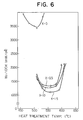
- a core loss W 2/100k at 0.2T and 100kHz was measured. The results are shown in Fig. 6.
- the proper heat treatment temperature range is 540-580°C, much higher than that for an alloy containing no Cu. This temperature is higher than the crystallization temperature Tx measured by DSC at a heating rate of 10°C/min.
- the dust core produced from the Fe-base soft magnetic alloy containing Cu according to the present invention contained fine crystalline particles in an amount of 50% or more.
- Alloy powder each having the composition shown in Table 7 was produced by a water atomizing method, and it was classified by a sieve to obtain powder of 0.32 mm (48 mesh) or smaller.
- the powder thus formed showed a halo pattern in an X-ray diffraction, which is peculiar to an amorphous alloy.
- the powder was mixed with 7 wt% of a heat-resistant varnish consisting of modified alkyl silicate and heated to about 530°C at a heating rate of 50°C/min while compressing, to conduct hot pressing at such temperature for 30 minutes.
- a heat-resistant varnish consisting of modified alkyl silicate
- Table 7 shows effective permeability ⁇ e 1k at 1kHz for each dust core.
- the Fe-base soft magnetic alloy dust cores of the present invention had saturation magnetic flux densities of IT or more and ⁇ e 1k higher than 1000. Therefore, they are highly suitable for noise filters, choke coils, etc.
- Amorphous alloy powder having the composition of Fe 73.5 Cu1Nb3Si 16.5 B6 in the form of a flake was produced by a cavitation method.
- this powder was mixed with water glass, aluminum phosphate, powdery acetone and methanol and compressed by die at 450°C under pressure of 15 kbar for 30 minutes to produce a dust core of 21 mm in outer diameter 12 mm in inner diameter and 8 mm in height.
- This dust core was then heat-treated at 530°C for 30 minutes. After measuring its magnetic properties, its X-ray diffraction was measured. As a result, it was confirmed that the dust core consisted substantially of a crystalline phase.
- Fig. 7 shows the increments of permeability by applying a DC magnetic field to the dust core (A) of the present invention, an Mo Permalloy dust core (B) and an Fe-Si-Al dust core (C), respectively.
- the dust core (A) of the present invention showed better permeability characteristics when a DC magnetic field was applied than the conventional dust cores. Accordingly, it is suitable for smoothing chokes for switching power supplies, etc.
- An amorphous alloy ribbon having the composition of Fe 71.5 Cu1Nb5Si 15.5 B7 with a width of 5 mm and a thickness of 15 ⁇ m was produced, and it was heated at 450°C for 1 hour. After cooling down to room temperature, it was pulverized to powder of 48 mesh or smaller by a vibration mill for 1 hour.
- this powder was mixed with water glass, aluminum phosphate, powdery acetone and methanol and compressed by die at 500°C under pressure of 15 kbar for 30 minutes to produce a dust core of 21 mm in outer diameter, 12 mm in inner diameter and 8 mm in height. This dust core was then heat-treated at 570°C for 30 minutes.
- the dust core of the present invention showed better frequency characteristics of effective permeability than the conventional Mo Permalloy dust core. Accordingly, it is suitable for various inductors used at high frequency.
Landscapes
- Engineering & Computer Science (AREA)
- Power Engineering (AREA)
- Chemical & Material Sciences (AREA)
- Dispersion Chemistry (AREA)
- Physics & Mathematics (AREA)
- Electromagnetism (AREA)
- Soft Magnetic Materials (AREA)
- Powder Metallurgy (AREA)
- Manufacture Of Metal Powder And Suspensions Thereof (AREA)
Description
- The present invention relates to Fe-base soft magnetic alloy powder having excellent magnetic properties and applications thereof, and more particularly to Fe-base soft magnetic alloy powder having a low magnetostriction, and applications thereof as transformers, choke coils, saturable reactors, etc. and methods of producing them.
- Conventionally, magnetic cores for transformers, motors, chokes, noise filters, etc. are made of crystalline materials such as Fe-Si alloys, Permalloy, ferrites, etc. Fe-Si alloys, however, have large specific resistance and their crystal magnetic anisotropy is not zero. Accordingly, they suffer from large core losses at a relatively high frequency. Permalloy also has a high core loss at a high frequency.
- Conventionally used widely as magnetic powder materials for high-frequency transformers, saturable reactors, choke coils, etc. are mainly ferrites having such advantages as low eddy current loss.
- However, despite the fact that ferrites have small core losses at a high frequency, their magnetic flux densities are at most 0.5 T. Accordingly, when they are operated at a large magnetic flux density, they are close to saturation, leading to large core losses.
- Recently, transformers operable at a high frequency, such as those for switching regulators are required to be miniaturized. For this purpose, the magnetic flux density in an operating region should be increased. Thus, the increase in a core loss of ferrites may become a serious problem for practical applications.
- For the purpose of decreasing a core loss at a high frequency and improving frequency characteristics of permeability, dust cores of crystalline magnetic alloys are conventionally used. The dust cores are prepared by forming fine powder of the magnetic alloys and solidifying it via insulating layers. For such insulating layers, organic materials are used. Such magnetic dust cores are mainly used for chokes, noise filters, etc.
- However, since the dust cores made of the conventional crystalline magnetic powder have small permeability, a large number of winding is necessary to achieve sufficient inductance, making it difficult to miniaturize magnetic cores constituted by such dust cores. In addition, since they have large core losses, a lot of heat is generated during their use.
- Recently, as an alternative to such conventional magnetic materials, amorphous magnetic alloys having high saturation magnetic flux densities have been attracting much attention.
- These amorphous alloys are essentially composed of Fe, Co or Ni, etc. as a basic element, and at least one of P, C, B, Si, Aℓ, Ge, etc. as a metalloid which can make the resulting alloys amorphous. Further, it is known that there are amorphous alloys composed of Fe, Co or Ni and Ti, Zr, Hf, Nb, etc. without metalloids, which can be produced by a roll method.
- However, since amorphous magnetic alloys are tough and difficult to be pulverized, they are generally produced in the form of a thin ribbon and the thin ribbon is laminated or wound to form a magnetic core.
- To form a magnetic core from the thin ribbon, it should be formed into a toroidal wound core or cut into a desired shape such as a U-shape or an E-shape and then laminated. However, when a U-shape or E-shape magnetic core is desired, its production is generally difficult.
- To eliminate this problem, various methods of producing dust cores by pulverizing an amorphous magnetic alloy and compressing the resulting powder together with a binder were proposed. See, for instance, Japanese Patent Laid-Open Nos. 55-133507, 61-154014, 61-154111, 61-166902, etc. Further, various methods of producing dust cores with high densities by instantaneously applying an impact force to amorphous magnetic alloy powder were proposed. See, for instance, Japanese Patent Laid-Open Nos. 61-288404 and 62-23905.
- Amorphous alloys which may be used for such dust cores are mainly classified into two categories: iron-base alloys and cobalt-base alloys. Fe-base amorphous alloys are advantageous in that they are less expensive than Co-base amorphous alloys, but they generally have larger core loss and lower permeability at high frequency than the Co-base amorphous alloys. On the other hand, despite the fact that the Co-base amorphous alloys have small core loss and high permeability at high frequency, their core loss and permeability vary largely as the time passes, posing problems in practical use. Further, since they contain as a main component an expensive cobalt, they are inevitably disadvantageous in terms of cost.
- In any case, alloy powder and dust cores having sufficiently high saturation magnetic flux density and other good magnetic properties cannot be obtained from Fe-base or Co-base amorphous alloys.
- An Fe-base soft magnetic alloy powder according to the first part of claim 1 is described in EP-A-0271657.
- Therefore, an object of the present invention is to provide an Fe-base soft magnetic alloy powder having excellent magnetic characteristics such as a saturation magnetic flux density, etc.
- Another object of the present invention is to provide a method of producing such Fe-base soft magnetic alloy powder.
- A further object of the present invention is to provide an Fe-base soft magnetic alloy dust core having excellent soft magnetic properties, particularly a high saturation magnetic flux density, a small core loss and a small change of core loss with time, large permeability and other excellent magnetic properties.
- A further object of the present invention is to provide a method of producing such an Fe-base soft magnetic alloy dust core.
- Intense research in view of the above objects has revealed that the addition of Cu and at least one element selected from the group consisting of Nb, W, Ta, Zr, Hf, Ti and Mo to an Fe-base alloy, and a proper heat treatment of the Fe-base alloy which is once made amorphous can provide an Fe-base soft magnetic alloy, a major part of whose structure is composed of fine crystalline particles, and thus having excellent soft magnetic properties. The present invention is based on these findings.
- Thus, the Fe-base soft magnetic alloy powder according to the present invention has the composition represented by the general formula:
(Fe1-aMa)100-x-y-z-α-β-γCuxSiyBzM'αM''βXγ
wherein M is Co and/or Ni, M' is at least one element selected from the group consisting of Nb, W, Ta, Zr, Hf, Ti and Mo, M'' is at least one element selected from the group consisting of V, Cr, Mn, Aℓ, elements in the platinum group, Sc, Y, rare earth elements, Au, Zn, Sn and Re, X is at least one element selected from the group consisting of C, Ge, P, Ga, Sb, In, Be and As, and a, x, y, z, α, β and γ respectively satisfy 0≦a≦0.5, 0.1≦x≦3, 0≦y≦30, 0≦z≦25, 0≦y+z≦35, 0.1≦α≦30 0≦β≦10 and 0≦γ≦10, at least 50% of the alloy structure being fine crystalline particles having an average particle size of 50 nm or less when measured by their maximum sizes. - Further, the method of producing Fe-base soft magnetic alloy powder according to the present invention comprises the steps of rapidly quenching a melt of the above composition and heat-treating it to generate fine crystalline particles having an average particle size of 50 nm or less which constitute at least 50% of the alloy structure.
- The Fe-base soft magnetic alloy dust core according to the present invention is composed of compressed Fe-base soft magnetic alloy powder.
- The method of producing an Fe-base soft magnetic alloy dust core according to the present invention which comprises compressing fine powder of the Fe-base soft magnetic alloy together with a binder and/or an electrically insulating material.
-
- Fig. 1 is a schematic view showing an apparatus for producing the Fe-base alloy powder according to the present invention;
- Fig. 2 (a) is a graph showing an X-ray diffraction pattern of the Fe-base alloy powder of Example 1 before heat treatment;
- Fig. 2 (b) is a graph showing an X-ray diffraction pattern of the Fe-base soft magnetic alloy of the present invention after heat treatment;
- Fig. 3 is a transmission electron photomicrograph (magnification: 300,000) of the Fe-base soft magnetic alloy powder of Example 1 after heat treatment;
- Fig. 4 is a graph showing the relations between Cu content (x) and a core loss W2/100k with respect to the Fe-base soft magnetic alloy of Example 13;
- Fig. 5 is a graph showing the relations between M′ content (α) and a core loss W2/100k with respect to the Fe-base soft magnetic alloy of Example 14;
- Fig. 6 is a graph showing the relations between heat treatment temperature and a core loss with respect to the Fe-base soft magnetic alloy of Example 19;
- Fig. 7 is a graph showing the relations between incremental permeability and magnetic field strength with respect to the Fe-base soft magnetic alloy of Example 21; and
- Fig. 8 is a graph showing the relations between effective permeability and frequency with respect to the Fe-base soft magnetic alloy of Example 22.
- In the Fe-base soft magnetic alloy of the present invention, Fe may be substituted by Co and/or Ni in the range from 0 to less than 0.5. However, to have good magnetic properties such as a low core loss, the content of Co and/or Ni which is represented by "a" is preferably 0-0.3.
- In the present invention, Cu is an indispensable element, and its content "x" is 0.1-3 atomic %. When it is less than 0.1 atomic %, substantially no effect on the reduction of a core loss and on the increase in permeability can be obtained by the addition of Cu. On the other hand, when it exceeds 3 atomic %, the alloy's core loss becomes larger than those containing no Cu, reducing the permeability, too. The preferred content of Cu in the present invention is 0.5-2 atomic %, in which range the core loss is particularly small and the permeability is high.
- The reasons why the core loss decreases and the permeability increases by the addition of Cu are not fully clear, but it may be presumed as follows:
- Since Cu and Fe have a positive interaction parameter which makes their solubility low, iron atoms and copper atoms tend to gather separately to form clusters when heat-treated, thereby producing compositional fluctuation. This produces a lot of domains likely to be crystallized to provide nuclei for generating fine crystalline particles. These crystalline particles are based on Fe, and since Cu is substantially not soluble in Fe, Cu is ejected from the fine crystalline particles, whereby the Cu content in the vicinity of the crystalline particles becomes high. This presumably suppresses the growth of crystalline particles.
- Because of the formation of a large number of nuclei and the suppression of the growth of crystalline particles by the addition of Cu, the crystalline particles are made fine, and this phenomenon is accelerated by the inclusion of Nb, Ta, W, Mo, Zr, Hf, Ti, etc.
- Without Nb, Ta, W, Mo, Zr, Hf, Ti, etc., the crystalline particles are not fully made fine and thus the soft magnetic properties of the resulting alloy are poor. Particularly Nb and Mo are effective, and particularly Nb acts to keep the crystalline particles fine, thereby providing excellent soft magnetic properties. And since a fine crystalline phase based on Fe is formed, the Fe-base soft magnetic alloy has smaller magnetostriction than Fe-base amorphous alloys, which means that the Fe-base soft magnetic alloy has smaller magnetic anisotropy due to internal stress-strain, resulting in improved soft magnetic properties.
- Without the addition of Cu, the crystalline particles are unlikely to be made fine. Instead, a compound phase is likely to be formed and crystallized, thereby deteriorating the magnetic properties.
- Si and B are elements particularly for making fine the alloy structure. The Fe-base soft magnetic alloy is desirably produced by once forming an amorphous alloy with the addition of Si and B, and then forming fine crystalline particles by heat treatment.
- The content of Si ("y") and that of B ("z") are 0≦y≦30 atomic %, 0≦z≦25 atomic %, and 0≦y+z≦35 atomic %, because the alloy would have an extremely reduced saturation magnetic flux density if otherwise. When other amorphous-forming elements are contained in small amounts, y+z should be 10-35 atomic % to facilitate the production of an amorphous alloy.
- In the present invention, the preferred range of y is 10-25 atomic %, and the preferred range of z is 3-12 atomic %, and the preferred range of y+z is 18-28 atomic %. In these ranges, the Fe-base soft magnetic alloy is provided with a low core loss.
- In the present invention, M′ acts when added together with Cu to make the precipitated crystalline particles fine. M′ is at least one element selected from the group consisting of Nb, W, Ta, Zr, Hf, Ti and Mo. These elements have a function of elevating the crystallization temperature of the alloy, and synergistically with Cu having a function of forming clusters and thus lowering the crystallization temperature, it suppresses the growth of the precipitated crystalline particles, thereby making them fine.
- The content of M′ (α) is 0.1-30 atomic %. When it is less than 0.1 atomic %, sufficient effect of making crystalline particles fine cannot be obtained, and when it exceeds 30 atomic % an extreme decrease in a saturation magnetic flux density ensues. The preferred content of M′ is 2-8 atomic %, in which range particularly excellent soft magnetic properties are obtained. Incidentally, most preferable as M′ is Nb and/or Mo, and particularly Nb in terms of magnetic properties. The addition of M′ provides the Fe-base soft magnetic alloy with as high permeability as that of the Co-base high-permeability materials.
- M˝, which is at least one element selected from the group consisting of V, Cr, Mn, Aℓ, elements in the platinum group, Sc, Y, rare earth elements, Au, Zn, Sn and Re, may be added for the purposes of improving corrosion resistance and magnetic properties and of adjusting magnetostriction, but its content is at most 10 atomic %. When the content of M˝ exceeds 10 atomic %, an extremely decrease in a saturation magnetic flux density ensues. A particularly preferred amount of M˝ is 8 atomic % or less.
- Among them, at least one element selected from the group consisting of Ru, Rh, Pd, Os, Ir, Pt, Au, Cr and V is capable of providing the alloy with particularly excellent corrosion resistance and wear resistance.
- The alloy of the present invention may contain 10 atomic % or less of at least one element X selected from the group consisting of C, Ge, P, Ga, Sb, In, Be, As. These elements are effective for making amorphous, and when added with Si and B, they help make the alloy amorphous and also are effective for adjusting the magnetostriction and Curie temperature of the alloy. The preferred amount of X is 5 atomic % or less.
- In sum, in the Fe-base soft magnetic alloy having the general formula:
(Fe1-aMa)100-x-y-z-α-β-γCuxSiyBzM'αM''βXγ,
the general ranges of a, x, y, z, α, β and γ are
0≦a<0.5
0.1≦x≦3
0≦y≦30
0≦z≦25
0≦y+z≦35
0.1≦α≦30
0≦β≦10
0≦γ≦10,
and the preferred ranges are
0≦a≦0.3
0.5≦x≦2
10≦y≦25
3≦z≦12
18≦y+z≦28
2≦α≦8
β≦8
γ≦5. - In the Fe-base soft magnetic alloy having the above composition according to the present invention, at least 50% of the alloy structure consists of fine crystalline particles. These crystalline particles are based on α-Fe having a bcc structure, in which Si and B, etc. are dissolved. These crystalline particles have an extremely small average particle size of 50 nm or less, and are uniformly distributed in the alloy structure. Incidentally, the average paticle size of the crystalline particles is determined by measuring the maximum size of each particle and averaging them. When the average particle size exceeds 50 nm, good soft magnetic properties are not obtained. It is preferably 20 nm or less and particularly 5 to 20 nm. The remaining portion of the alloy structure other than the fine crystalline particles is mainly amorphous. Even with fine crystalline particles occupying substantially 100% of the alloy structure, the Fe-base soft magnetic alloy of the present invention has sufficiently good magnetic properties.
- Incidentally, with respect to inevitable impurities such as N, O, S, etc., it is to be noted that the inclusion thereof in such amounts as not to deteriorate the desired properties is not regarded as changing the alloy composition suitable for magnetic cores, etc.
- Next, the method of producing the Fe-base soft magnetic alloy powder of the present invention will be explained in detail below.
- First, a melt of the above composition is rapidly quenched by various methods.
- The first method comprises rapidly quenching an alloy melt having the above composition to provide amorphous alloy powder and then heat-treating the powder.
- The amorphous alloy powder can be produced by a water atomizing method, a gas atomizing method, a spray method, a cavitation method, a spark errosion method, a method of ejecting a melt into a rotating liquid, etc. The amorphous alloy powder is desirably completely amorphous, but it may contain a crystalline phase.
- The second method comprises rapidly quenching an alloy melt having the above composition to provide amorphous alloy ribbons, flakes or wires, heat-treating them to make them brittle, pulverizing them, and then heat-treating them to generate fine crystalline particles. Incidentally, the amorphous alloy ribbons, flakes or wires can be produced by a single roll method, a double roll method, a centrifugal quenching method, a method of spinning into a rotating liquid, etc. The first heat treatment is conducted at a temperature between a temperature which is lower than their crystallization temperatures by about 250 °C and their crystallization temperatures for a sufficient period of time for making them brittle, usually for 1-3 hours.
- The third method comprises rapidly quenching an alloy melt having the above composition to provide amorphous alloy ribbons, flakes or wires, causing them to absorb a hydrogen gas at a temperature lower than their crystallization temperatures for a sufficient period of time for making them brittle, pulverizing them to power, and then heat-treating the powder. The absorption of a hydrogen gas in the amorphous alloy ribbons, flakes or wires can be achieved by placing them in a pressurized hydrogen gas atmosphere, or by using them as a cathod in an electrolytic both for hydrogen production.
- The fourth method comprises rapidly quenching an alloy melt having the above composition to provide brittle amorphous alloy ribbons, flakes or wires, pulverizing them to amorphous alloy powder, and then heat-treating the powder. The brittle amorphous alloy ribbons, flakes or wires can be produced by reducing a cooling rate of the alloy melt, specifically, by slowing the rotation of a roll for quenching the alloy melt or by making the ribbons, flakes or wires thicker, etc.
- The fifth method comprises rapidly quenching an alloy melt having the above composition to provide amorphous alloy ribbons, flakes or wires, heat-treating them, and then pulverizing them to powder. When the amorphous alloy ribbons, flakes or wires are heat-treated at a temperature higher than their crystallization temperatures, they are made so brittle that they can easily be pulverized by a ball mill, a vibration mill, etc.
- In each of the above methods, the heat treatment is carried out by heating the amorphous alloy in the form of powder, ribbon, flake, wire, etc. in vacuum or in an inert gas atmosphere such as hydrogen, nitrogen, argon, etc. The temperature and time of the heat treatment vary depending upon the composition of the amorphous alloy ribbon and the shape and size of a magnetic core made from the amorphous alloy powder. In general, it is heated at a temperature higher than its crystallization temperature for a sufficient period of time for making it brittle. Specifically, it is preferably 450-700°C for 5 minutes to 24 hours. When the heat treatment temperature is lower than 450°C, crystallization is unlikely to take place with ease, requiring too much time for the heat treatment. On the other hand, when it exceeds 700°C, coarse crystalline particles tend to be formed, making it difficult to obtain fine crystalline particles. And with respect to the heat treatment time, when it is shorter than 5 minutes, it is difficult to heat the overall worked alloy at uniform temperature, providing uneven magnetic properties, and when it is longer than 24 hours, productivity becomes too low and also the crystalline particles grow excessively, resulting in the deterioration of magnetic properties. The preferred heat treatment conditions are, taking into consideration practicality and uniform temperature control, etc., 500-650°C for 5 minutes to 6 hours.
- It is preferable to cool the alloy powder or the dust core rapidly after heat treatment. For this purpose, the alloy powder or the dust core is taken out of a heat treatment furnace and left to stand in the air or immersed in an oil, etc.
- The heat treatment atmosphere is preferably an inert gas atmosphere, but it may be an oxidizing atmosphere such as the air. Cooling may be carried out properly in the air or in a furnace. And the heat treatment may be conducted by a plurality of steps.
- The heat treatment can be carried out in a magnetic field to provide the alloy with magnetic anisotropy. The magnetic field need not be applied always during the heat treatment, and it is necessary only when the alloy is at a temperature lower than the Curie temperature Tc thereof. In the present invention, the alloy has an elevated Curie temperature because of crystallization than the amorphous counterpart, and so the heat treatment in a magnetic field can be carried out at temperatures higher than the Curie temperature of the corresponding amorphous alloy. In a case of the heat treatment in a magnetic field, it may be carried out by two or more steps. Also, a rotational magnetic field can be applied during the heat treatment.
- Incidentally, the Fe-base soft magnetic alloy of the present invention can be produced by other methods than liquid quenching methods, such as vapor deposition, ion plating, sputtering, etc.
- The Fe-base soft magnetic alloy powder according to the present invention may be in the form of a fine plate-like particle having a length less than 100 µm and a uniform thickness. The alloy powder having a particle size less than 5 mm (4 mesh) can be produced from the amorphous alloy ribbons and flakes in the methods 2 - 5. Such powder can be bonded with a resin to form electromagnetic wave-shielding sheets, etc.
- With respect to substantially sphere powder, it can be produced by a spark errosion method, by ejecting an alloy melt onto a rotating slanted disc to form sphere melt drops which are then thrown into a rotating water, or by ejecting an alloy melt into a rotating coolant. Such sphere powder usually has a particle size of 200 µm or less.
- With respect to powder of irregular shape, it can be produced by a water atomizing method, etc. The irregular powder particles usually have a maximum size of 2 mm or less.
- In any case, both sphere powder and irregular powder may be heat-treated under the conditions as described above.
- The Fe-base soft magnetic alloy powder heat-treated according to the present invention may be plated with Cu, Cr, Ni, Au, etc., or coated with SiO₂, glass, an epoxy resin, etc. to improve its corrosion resistance or to form an insulating layer. Alternatively, it may be further heat-treated to form an oxide layer or a nitride layer thereon.
- Next, the Fe-base soft magnetic alloy dust core according to the present invention will be explained.
- The amorphous alloy powder as a starting material for the dust core may contain crystal phases, but the alloy structure is preferably amorphous to make sure the formation of uniform fine crystalline particles by a subsequent heat treatment.
- This amorphous alloy powder is compressed by a press, etc. to form a dust core. In this process, a binder such as a phenol resin, an epoxy resin, etc. is added. If a heat treatment is to be conducted after the compression process, a heat-resistant binder such as an inorganic varnish is desirable.
- When the dust core is produced without using a binder, the amorphous alloy powder is compressed at a temperature near its crystallization temperature for utilizing the deformation of the alloy by a viscous flow. Further a so-called explosion molding can be used to form a dust core.
- When the dust core is to be used for electric parts, insulating layers are desirably provided among the powder particles to decrease the eddy current loss of the resulting dust core. For this purpose, the surface of the amorphous alloy powder is oxidized or coated with a water glass, metal alkoxide, ceramic ultra-fine powder, etc., and then the alloy powder is compressed.
- A heat treatment can be conducted on the amorphous alloy in the form of powder. However, except that the alloy has no magnetostriction, the heat treatment is desirably conducted after it is formed into a dust core. The heat treatment conditions are as described above.
- The present invention will be explained in detail by the following Examples, without intention of restricting the scope of the present invention.
- A melt having the composition (by atomic %) of 1% Cu, 16.5% Si, 6% B, 3% Nb and balance (73.5%) substantially Fe was formed into a ribbon of 5mm in width and 20 µm in thickness by a single roll method. The X-ray diffraction of this ribbon showed a halo pattern peculiar to an amorphous alloy as shown in Fig. 2(a).
- The amorphous alloy ribbon thus formed was heat-treated in a furnace filled with a nitrogen gas at 510 °C for 1 hour, cooled to room temperature and then pulverized by a vibration mill for 1 hour. The resulting powder was mostly composed of particles of 0.075 mm (200 mesh) or smaller.
- Fig. 2(b) shows an X-ray diffraction of the heat-treated powder, and Fig. 3 shows a transmission electron photomicrograph (magnification: 300,000) of the heat-treated powder. It was confirmed by the X-ray diffraction and the transmission electron photomicrograph that the heat-treated alloy powder had crystalline particles, and that the crystalline particles had a particle size of about 10 to 20 nm. The X-ray diffraction shows that the crystalline particles were composed of an Fe solid solution having a bcc structure in which Si, etc. were dissolved.
- Next, this Fe-base soft magnetic alloy powder was measured with respect to magnetic properties by a vibration-type magnetometer (VSM). As a result, its saturation magnetic flux density Bs was 1.2 T, and its coercive force was 1.4 A/m (0.018 Oe), meaning that it had excellent soft magnetic properties.
- An amorphous alloy ribbon having the composition of Fe73.5Cu₁Nb₃Si17.5B₅ with a thickness of 30 µm and a width of 3 mm was produced by a double roll method, and it was heat-treated in a furnace filled with a nitrogen gas at 420 °C for 1 hour. After cooling down to room temperature, it was pulverized by a vibration mill for 2 hours. The resulting powder was mostly composed of particles of 0.075 mm (200 mesh) or smaller.
- The powder thus formed showed a halo pattern in an X-ray diffraction, which is peculiar to an amorphous alloy. The crystallization temperature of the alloy Powder was 495 °C when measured at a heating rate of 10 °C/min. Next, this powder was heat-treated at 510°C for 1 hour in a furnace and then cooled to room temperature at a cooling rate of 5 °C/min.
- It was observed by an X-ray diffraction measurement that the heat-treated powder showed peaks assignable to crystals as in Example 1. The transmission election microscopic observation showed that most of the alloy structure consisted of fine crystalline particles having a particle size of 10 to 20 nm.
- Next, this powder was measured with respect to magnetic properties by a vibration-type magnetometer (VSM). As a result, its saturation magnetic flux density Bs was 1.19 T and its Hc was 1.7 A/m (0.021 Oe).
- An amorphous alloy ribbon having the composition of Fe71.5Cu₁Nb₅Si15.5B₇ with a thickness of 30 µm and a width of 15 mm was produced by a single roll method. The ribbon was brittle. It was pulverized by a ball mill for 5 hours. The resulting powder was mostly composed of particles of 2 mm (10 mesh) or smaller. The crystallization temperature of the alloy powder was 534 °C when measured at a heating rate of 10°C/min.
- Next, this powder was heated to 570°C in an N₂ gas atmosphere at a heating rate of 5°C/min, kept at 570°C for 1 hour and then cooled to room temperature at a cooling rate of 3°C/min.
- It was observed by an X-ray diffraction measurement and a transmission electron microscopy that most of the alloy structure consisted of fine crystalline particles.
- Next, this powder was measured with respect to magnetic properties by a vibration-type magnetometer (VSM). As a result, its saturation magnetic flux density Bs was 1.07 T and its Hc was 0.96 A/m (0.012 Oe).
- An alloy powder having the composition of Fe73.5 Cu₁ Nb₃ Si12.5 B₁₀ was produced by a water atomizing method, and it was classified by a 0.042-mm (350-mesh) sieve. The powder thus formed showed a halo pattern in an X-ray diffraction, which is peculiar to an amorphous alloy. The crystallization temperature of the alloy powder was 500°C when measured at a heating rate of 10°C/min.
- Next, this powder was heat-treated in an Ar gas atmosphere at 550°C for 1 hour and then rapidly cooled to room temperature in the air. It was observed by an X-ray diffraction measurement that the heat-treated powder showed peaks assignable to crystals as in Example 1.
- Next, this powder was measured with respect to magnetic properties by a vibration-type magnetometer (VSM). As a result, its saturation magnetic flux density Bs was 1.28 T and its Hc was 1.7 A/m (0.021 Oe).
- Amorphous alloy flakes having the composition of Fe71.5 Cu₁ Mo₅ Si13.5 B₉ with a thickness of about 25 µm were produced by a cavitation method, and they were heated at 420°C for 1 hour in vacuum. After cooling down to room temperature, they were pulverized by a vibration mill for 1 hour. The resulting powder was mostly composed of particles of 0.075 mm (200 mesh) or smaller. The crystallization temperature of the alloy powder was 520°C when measured at a heating rate of 10°C/min.
- Next, this powder was heated to 570°C at a heating rate of 20°C/min, kept at 570°C for 1 hour, and then cooled to room temperature at a cooling rate of 5°C/min.
- It was observed by an X-ray diffraction measurement that the heat-treated powder showed peaks assignable to crystals as in Example 1.
- Next, this powder was measured with respect to magnetic properties by a vibration-type magnetometer (VSM). As a result, its saturation magnetic flux density Bs was 1.11 T and its Hc was 1.1 A/m (0.014 Oe).
- An amorphous alloy ribbon having the composition of (Fe0.99Ni0.01)73.5Cu₁Nb₃Si13.5B₉ with a thickness of 20 µm and a width of 10 mm was produced by a single roll method. It was pulverized at room temperature under hydrogen pressure of 15.5 kbar (155 kg/mm²) for 4 hours. The resulting powder had a particle size distribution of 0.15 to 0.075 mm (100-200 mesh) = 82%, 0.075 to 0.045 mm (200-325 mesh) = 14% and over 0.045 mm (325 mesh) = 4%. After removing the hydrogen pressure, it did not contain hydrogen. The crystallization temperature of the resulting alloy powder was 495°C when measured at a heating rate of 10°C/min.
- Next, this powder was heated to 530°C at a heating rate of 15°C/min, kept at 530°C for 1 hour and then cooled to room temperature at a cooling rate of 2.5°C/min.
- The heat-treated powder had fine crystalline particles mainly composed of Fe as in Example 1.
- Thin amorphous alloy ribbons having the compositions as shown in Table 1 were prepared by a single roll method, and each of the ribbons was heat-treated at 440°C for 1 hour and then pulverized by a vibration mill. After that, each powder was heat-treated by heating at a temperature higher than its crystallization temperature by 50 °C for 1 hour and then cooling it to room temperature.
- The resulting powder, mostly 0.075 mm (200 mesh) or smaller, had fine crystalline particles as in Example 1. For each powder, a saturation magnetic flux density Bs and a coercive force Hc were measured. Incidentally, for each powder in an amorphous state (before heat treatment), its crystallization temperature Tx was also measured. The results are shown in Table 1.

- Amorphous alloy ribbons having the compositions shown in Table 2 were produced by a single roll method. Next, each of these amorphous alloy ribbons was heat-treated at 430°C for 1 hour and then pulverized by a vibration mill. Subsequently, the resulting powder was heated at a temperature higher than its crystallization temperature by 20°C for 1 hour while applying a magnetic field of 40 kA/m (5000 Oe) and then cooled to room temperature.
- The resulting powder, mostly 200 mesh or smaller, had fine crystalline particles in its alloy structure as in Example 1. For each powder, a saturation magnetic flux density Bs and a coercive force Hc were measured. Incidentally, for each powder in an amorphous state (before heat treatment), its crystallization temperature Tx was also measured. The results are shown in Table 2.

- Amorphous alloy powder of Fe73.5Cu₁Nb₃Si15.5B₇ was produced by an apparatus shown in Fig. 1. In Fig. 1, the apparatus comprises a nozzle 1 surrounded by a
heater 2 for containing analloy melt 3, aserrated roll 4 rotating in the direction shown by R, acooling roll 6 rotating in the direction shown by R′, a guide 7 and acollector 8. Thealloy melt 3 was ejected from the nozzle 1 onto theserrated roll 4 to divide it into small droplets 5, which were then caused to collide with thecooling roll 6. When brought into contact with thecooling roll 6, the melt droplets 5 were rapidly quenched to amorphous alloy powder, which was then collected. - The resulting powder had an alloy structure in which fine crystalline particles were dispersed as in Example 1.
- Next, this powder was mixed with a polyethylene chlolide resin in a ratio of 62:38 by volume to form a composite sheet of 1.0 mm in thickness. This sheet was measured with respect to electromagnetic wave-shielding characteristics. As a result, it was confirmed that it had a shielding effect of 85 dB at 100kHz.
- A melt having the composition (by atomic %) of 1% Cu, 15% Si, 9% B, 3% Nb, 1% Cr and balance substantially Fe was formed into a ribbon of 20 mm in width and 18 µm in thickness by a single roll method. The X-ray diffraction of this ribbon showed a halo pattern peculiar to an amorphous alloy. Its transmission electron photomicrograph (magnification: 300,000) was taken. It was confirmed by the X-ray diffraction and the transmission electron photomicrograph that the ribbon was almost completely amorphous.
- The amorphous alloy ribbon was heat-treated in a nitrogen gas atmosphere at 300°C for 30 minutes, cooled to room temperature and then pulverized by a vibration mill to provide powder of 0.32 mm (48 mesh) or smaller. The scanning electron microscopic (SEM) observation showed that the resulting powder was mostly composed of flaky particles.
- As a result of an X-ray diffraction of the heat-treated powder, a halo pattern as in Fig. 2 (a) was observed. Thus, it was confirmed that the powder was substantially amorphous at this stage.
- The powder was then mixed with 7 wt% of a heat-resistant inorganic varnish (modified alkyl silicate) as a binder and subjected to pressing at about 250°C to produce a dust core of 20 mm in outer diameter, 12 mm in inner diameter and 6 mm in thickness.
- This core was heat-treated at 550°C for 1 hour in a nitrogen gas atmosphere and then slowly cooled. Similarly, the above amorphous alloy powder was heat-treated under the same conditions. Both of them were measured by X-ray diffraction. Thus, crystal peaks as in Fig. 2 (b) were observed for both of them. Further, by a transmission electron microscopic observation ( x 300,000), it was confirmed that most of the alloy structures after heat treatment were composed of fine crystalline particles having an average particle size of about 100Å.
- The alloy of the present invention containing both Cu and Nb contained substantially sphere crystalline particles whose average particle size was as small as about 10 nm. It was presumed from an X-ray diffraction pattern and a transmission electron microscopy that these crystalline particles were an α-Fe solid solution in which Si, B, etc. were dissolved. When Cu was not contained, the crystalline particles became larger. Thus, it was confirmed that the addition of Cu and Nb extremely affected the size and shape of crystalline particles dispersed in the alloy structure.
- Next, the dust cores before and after heat treatment were measured with respect to a core loss W2/100k at a maximum wave height of a magnetic flux density Bm=0.2T and a frequency of 100kHz. As a result, the core loss was 7500mW/cm³ for the dust core before heat treatment and 530mW/cm³ for that after heat treatment. Thus, it has been verified that the heat treatment of the present invention generates fine crystalline particles uniformly in the alloy structure, leading to remarkable decrease in a core loss.
- Fe-base amorphous alloy dust cores having the compositions as shown in Table 3 were prepared under the same conditions as in Example 10. The resulting alloys were classified into 2 groups, and those in one group were subjected to the same heat treatment as in Example 11, and those in the other group were subjected to a conventional heat treatment (400°C x 1 hour) to keep an amorphous state. They were then measured with respect to core loss W2/100k at 100kHz and 0.2T. The results are shown in Table 3.


- Table 3 shows that the heat treatment of the present invention can generate fine crystalline particles uniformly in the amorphous alloy structure, thereby decreasing the alloy's core loss.
- Each of amorphous alloy dust cores having the composition of Fe73-xCuxNb₃Si₁₄B₉Cr₁(0≦x≦3.5) was produced in the same manner as in Example 10, and heat-treated at the following optimum heat treatment temperature for one hour, and then measured with respect to a core loss W2/100k at a wave height of magnetic flux density Bm=0.2T and a frequency f=100kHz.
X (atomic %) Heat Treatment Temperature (°C) 0 510 0.05 515 0.1 530 0.5 550 1.0 570 1.5 570 2.0 560 2.5 540 3.0 510 3.2 500 3.5 490 - The relations between the content x of Cu (atomic %) and the core loss W2/100k are shown in Fig. 4. It is clear from Fig. 4 that the core loss decreases as the Cu content x increases from 0, but that when it exceeds about 3 atomic %, the core loss becomes as large as that of alloys containing no Cu. When x is in the range of 0.1-3 atomic %, the core loss is sufficiently small. Particularly desirable range of x appears to be 0.5-2 atomic %.
- Each of amorphous alloy dust cores having the composition of Fe75.5-αCu₁Si₁₃B9.5M′α Ti₁(M′=Nb, W, Ta or Mo) was produced in the same manner as in Example 10, heat-treated at the following optimum heat treatment temperature for one hour, and then measured with respect to a core loss W2/100k.
α (atomic %) Heat Treatment Temperature (°C) 0 410 0.1 420 0.2 425 1.0 445 2.0 500 3.0 550 5.0 580 7.0 590 8.0 600 10.0 600 11.0 605 - The results are shown in Fig. 5, in which graphs A, B, C and D show the alloys in which M′ are Nb, W, Ta and Mo, respectively.
- As is clear from Fig. 5, the core loss is sufficiently small when the amount α of M′ is in the range of 0.1-10 atomic %. And particularly when M′ is Nb, the core loss was extremely low. A particularly desired range of α is 2≦α≦8.
- Alloy powder having the composition of Fe₇₂Cu₁Si13.5B9.5Nb₃Ru₁ was produced by a water atomizing method and classified by a sieve to obtain powder of 0.32 mm (48 mesh) or smaller. As a result of X-ray diffraction measurement, a halo pattern was observed. Thus, it was confirmed that the alloy powder was almost completely amorphous. The powder was mixed with 0.7% water glass (JIS No. 3) and stirred sufficiently. After that, it was dried at 180°C for 2 hours.
- This powder was solidified to a bulk by using an impact compression method. Thus, a toroidal (doughnut-shaped) magnetic core of 20 mm in outer diameter, 12 mm in inner diameter and 5 mm in thickness was obtained. Incidentally, the solidification of the alloy powder was conducted by using an impact gun at impact pressure of 7 GPa to provide a core having a density of 97%.
- After heat treatment at 550°C for 1 hour, it was measured with respect to a saturation magnetic flux density Bs, effective permeability µe1k at 1kHz and a core loss W1/10k at 0.1T and 10kHz. For comparison, effective permeability was also measured for an Fe-base amorphous alloy dust core (Fe₇₈B₁₃Si₉), a Co-base amorphous alloy dust core (Co70.3Fe4.7Si₁₅B₁₀) and an Mo Permalloy dust core. The results are shown in Table 4. Incidentally, the Fe-base amorphous alloy dust core was produced in the same manner as the Fe₇₂Cu₁Si13.5B9.5Nb₃Ru₁ dust core except for heat treatment. The Fe-base amorphous alloy dust core was annealed at 400°C for 2 hours, which could keep the amorphous state of the alloy.

- It is clear from Table 4 that the Fe-base soft magnetic alloy dust core of the present invention has a higher saturation magnetic flux density than those of the Co-base amorphous alloy dust core and the Permalloy dust core, and that it also has higher permeability and a smaller core loss than those of the Fe-base amorphous alloy dust core. Therefore, the Fe-base soft magnetic alloy dust core of the present invention is suitable for choke coils, etc.
- Amorphous alloy ribbons having the compositions shown in Table 5 were treated in the same manner as in Example 1 to provide Fe-base soft magnetic alloy dust cores. Table 5 shows the corrosion resistance and core loss variation ΔW of each dust core after keeping it at a high temperature and a high humidity (80°C, 95% RH) for 1000 hours.


- It is clear from Table 5 that the Fe-base soft magnetic alloy dust cores of the present invention containing one or more of Ru, Rh, Pd, Os, Ir, Pt, Au, Cr, Ti and V had excellent corrosion resistance, small core loss change at high temperature and high humidity. Thus, they can be used in severe environment.
- A melt having the composition (by atomic %) of 1% Cu, 13.8% Si, 8.9% B, 3.2% Nb and balance substantially Fe was formed into a ribbon of 10mm in width and 18 µm in thickness by a single roll method. The X-ray diffraction of this ribbon showed a halo pattern peculiar to an amorphous alloy. A transmission electron photomicrograph (magnification: 300,000) of this ribbon shows that the resulting ribbon was almost completely amorphous.
- Next, this amorphous ribbon was heat-treated in a nitrogen gas atmosphere at 570°C for one hour. It is evident from a transmission electron photomicrograph (magnification: 300,000) of the heat-treated ribbon that most the alloy structure of the ribbon after the heat treatment consisted of fine crystalline particles. The crystalline particles had an average particle size of about 10 nm.
- In view of the fact that the crystalline particles become coarse when there is no Cu, the addition of both Cu and Nb, etc. has a remarkable effect of making the crystalline particles fine in the alloy structure.
- The heat-treated ribbon was pulverized to 0.32 mm (48 mesh) or smaller by a vibration mill, and then formed into a dust core of 20 mm in outer diameter, 12 mm in inner diameter and 6 mm in thickness in the same manner as in Example 10.
- On the other hand, the same amorphous alloy ribbon was subjected to a conventional heat treatment (400°C x 1 hour) to keep its amorphous state and then formed into a dust core of the same shape in the same manner as above.
- For both dust cores, a core loss was measured at a maximum wave height of a magnetic flux density Bm=0.2T and a frequency of 100kHz. As a result, the core loss W2/100k was 5500 mW/cm³ for the dust core subjected to the conventional heat treatment and 930 mW/cm³ for that of the present invention. This means that because fine crystalline particles are uniformly formed in the alloy structure according to the present invention, the core loss decreases extremely.
- Under the same conditions as in Example 16, Fe-base alloy dust cores having the compositions shown in Table 6 were produced. For those to which the heat treatment of the present invention was conducted in the state of a ribbon and those to which the conventional heat treatment was conducted to keep their amorphous state, a core loss W2/100k was measured. The results are shown in Table 6. The comparison of the data shows that the heat treatment of the present invention can provide the alloy with a low core loss.


- Amorphous alloy ribbons having the composition of Fe73-xCuxSi₁₃B₉Nb₃Cr₁C₁ (x=0, 0.5, 1.0 and 1.5) were formed into dust cores of 20 mm in outer diameter, 12 mm in inner diameter and 6 mm in thickness in the same manner as in Example 10. Each dust core was heat-treated at various temperatures for 1 hour. For each dust core, a core loss W2/100k at 0.2T and 100kHz was measured. The results are shown in Fig. 6.
- Incidentally, the crystallization temperature Tx of the amorphous alloy for each dust core was measured by a differential scanning calorimeter (DSC) at a heating rate of 10°C/min. As a result, it was 580°C for x=0 and 505°C for x=0.5, 1.0 and 1.5.
- As is clear form Fig. 6, when the Cu content x was 0, the core loss W2/100k was extremely large. The addition of Cu leads to the decrease in a core loss. Thus, the proper heat treatment temperature range is 540-580°C, much higher than that for an alloy containing no Cu. This temperature is higher than the crystallization temperature Tx measured by DSC at a heating rate of 10°C/min.
- As a result of a transmission electron microscopic observation, it was confirmed that the dust core produced from the Fe-base soft magnetic alloy containing Cu according to the present invention contained fine crystalline particles in an amount of 50% or more.
- Alloy powder each having the composition shown in Table 7 was produced by a water atomizing method, and it was classified by a sieve to obtain powder of 0.32 mm (48 mesh) or smaller. The powder thus formed showed a halo pattern in an X-ray diffraction, which is peculiar to an amorphous alloy.
- Next, the powder was mixed with 7 wt% of a heat-resistant varnish consisting of modified alkyl silicate and heated to about 530°C at a heating rate of 50°C/min while compressing, to conduct hot pressing at such temperature for 30 minutes. Thus, dust cores of 20 mm in outer diameter, 12 mm in inner diameter and 6 mm in thickness were obtained.
- The X-ray diffraction of the dust core revealed that it showed crystal peaks, meaning that it was finely crystallized.
- Table 7 shows effective permeability µe1k at 1kHz for each dust core.

- The Fe-base soft magnetic alloy dust cores of the present invention had saturation magnetic flux densities of IT or more and µe1k higher than 1000. Therefore, they are highly suitable for noise filters, choke coils, etc.
- Amorphous alloy powder having the composition of Fe73.5Cu₁Nb₃Si16.5B₆ in the form of a flake was produced by a cavitation method.
- Next, this powder was mixed with water glass, aluminum phosphate, powdery acetone and methanol and compressed by die at 450°C under pressure of 15 kbar for 30 minutes to produce a dust core of 21 mm in
outer diameter 12 mm in inner diameter and 8 mm in height. This dust core was then heat-treated at 530°C for 30 minutes. After measuring its magnetic properties, its X-ray diffraction was measured. As a result, it was confirmed that the dust core consisted substantially of a crystalline phase. - Fig. 7 shows the increments of permeability by applying a DC magnetic field to the dust core (A) of the present invention, an Mo Permalloy dust core (B) and an Fe-Si-Aℓ dust core (C), respectively.
- The dust core (A) of the present invention showed better permeability characteristics when a DC magnetic field was applied than the conventional dust cores. Accordingly, it is suitable for smoothing chokes for switching power supplies, etc.
- An amorphous alloy ribbon having the composition of Fe71.5Cu₁Nb₅Si15.5B₇ with a width of 5 mm and a thickness of 15 µm was produced, and it was heated at 450°C for 1 hour. After cooling down to room temperature, it was pulverized to powder of 48 mesh or smaller by a vibration mill for 1 hour.
- Next, this powder was mixed with water glass, aluminum phosphate, powdery acetone and methanol and compressed by die at 500°C under pressure of 15 kbar for 30 minutes to produce a dust core of 21 mm in outer diameter, 12 mm in inner diameter and 8 mm in height. This dust core was then heat-treated at 570°C for 30 minutes.
- Next, this dust core was coated with an epoxy resin and then measured with respect to the dependency of effective permeability µe on frequency. As a result of an X-ray diffraction observation, crystal peaks were observed, meaning that the alloy was almost completely crystallized. The results are shown by (D) in Fig. 8. For comparison, the effective permeability of an Mo Permalloy dust core (E) was also shown.
- The dust core of the present invention showed better frequency characteristics of effective permeability than the conventional Mo Permalloy dust core. Accordingly, it is suitable for various inductors used at high frequency.
Claims (21)
- Fe-base soft magnetic alloy powder having the composition represented by the general formula:
(Fe1-aMa)100-x-y-z-α-β-γCuxSiyBzM'αM''βXγ
wherein M is Co and/or Ni, M' is at least one element selected from the group consisting of Nb, W, Ta, Zr, Hf, Ti and Mo, M'' is at least one element selected from the group consisting of V, Cr, Mn, Aℓ, elements in the platinum group, Sc, Y, rare earth elements, Au, Zn, Sn and Re, X is at least one element selected from the group consisting of C, Ge, P, Ga, Sb, In, Be and As, and a, x, y, z, α, β and γ respectively satisfy 0≦a≦0.5, 0.1≦x≦3, 0≦y≦30, 0≦z≦25, 0≦y+z≦35, 0.1≦α≦30, 0≦β≦10 and 0≦γ≦10, at least 50% of the alloy structure being fine crystalline particles having an average particle size of 50 nm or less,
wherein the powder particles are in the form of fine flakes having a particle size less than 5 mm (4 mesh), preferably smaller than 2 mm (10 mesh), at a substantially uniform thickness of less than 100 µm; or are substantially in the form of spheres having a particle size of 200 µm or less when measured along their maximum diameters. - The Fe-base sort magnetic alloy powder according to claim 1, wherein said a, x, y, z, α, β and γ respectively satisfy 0≦a≦0.3, 0.5≦x≦2, 10≦y≦25, 3≦z≦12, 18≦y+z≦28, 2≦α≦8, β≦8 and γ≦5.
- The Fe-base soft magnetic alloy powder according to claim 1 or 2, wherein said crystalline particles are substantially composed of an Fe solid solution having a bcc structure.
- The Fe-base soft magnetic alloy powder according to any of claims 1 to 3, wherein the balance of said alloy structure is substantially amorphous.
- The Fe-base soft magnetic alloy powder according to any of claims 1 to 4, wherein said alloy structure substantially consists of fine crystalline particles.
- A method of producing Fe-base soft magnetic alloy powder according to any of claims 1 to 5, comprising the steps of:(a) rapidly quenching a melt of the composition to form amorphous alloy powder; and(b) heat-treating said amorphous alloy powder to generate fine crystalline particles having an average particle size of 50 nm or less, in a proportion of at least 50% of the alloy structure.
- The method according to claim 6, wherein said amorphous alloy powder is formed by an atomizing method or a cavitation method.
- A method of producing Fe-base soft magnetic alloy powder according to any of claims 1 to 5, comprising the steps of:(a) rapidly quenching a melt of the composition to form an amorphous alloy in the form of a ribbon, a flake or a wire;(b) heating it at a temperature between a temperature which is lower than the crystallization temperature of said amorphous alloy by 250°C and said crystallization temperature, for a period of time necessary for making said amorphous alloy brittle;(c) pulverizing the resulting brittle amorphous alloy to powder;(d) heating said powder at a temperature higher than said crystallization temperature, thereby generating fine crystalline particles having an average particle size of 50 nm or less, in a proportion of at least 50% of the alloy structure.
- A method of producing Fe-base soft magnetic alloy powder according to any of claims 1 to 5, comprising the steps of:(a) rapidly quenching a melt of the composition to form an amorphous alloy in the form of a ribbon, a flake or a wire;(b) causing said amorphous alloy to absorb hydrogen at a temperature lower than the crystallization temperature, of said amorphous alloy for a period of time necessary for making said amorphous alloy brittle;(c) pulverizing the resulting brittle amorphous alloy to powder;(d) heating said powder at a temperature higher than said crystallization temperature, thereby generating five crystalline particles having an average particle size of 50 nm or less, in a proportion of at least 50% of the alloy structure.
- A method of producing Fe-base soft magnetic alloy powder according to any of claims 1 to 5, comprising the steps of:(a) rapidly quenching a melt of the composition to form an amorphous alloy in the form of a ribbon, a flake or a wire;(b) pulverizing said amorphous alloy to powder;(c) heating said powder at a temperature higher than said crystallization temperature, thereby generating five crystalline particles having an average particle size of 50 nm or less, in a proportion of at least 50% of the alloy structure.
- A method of producing Fe-base soft magnetic alloy powder according to any of claims 1 to 5, comprising the steps of(a) rapidly quenching a melt of the composition to form a brittle amorphous alloy in the form of a ribbon, a flake or a wire;(b) heating said amorphous alloy at a temperature higher than the crystallization temperature, of said amorphous alloy thereby generating fine crystalline particles having an average particle size of 50 nm or less, in a proportion of at least 50% of the alloy structure; and(c) pulverizing said alloy to powder.
- The method according to any of claims 6 to 11, wherein part or all of said steps are conducted in an inert gas atmosphere or in vacuum.
- The method according to claim 12, wherein said heat treatment step is conducted in a magnetic field.
- An Fe-base soft magnetic alloy dust core composed of compressed Fe-base soft magnetic alloy fine powder according to any of claims 1 to 5.
- The Fe-base soft magnetic alloy dust core according to claim 14, wherein said M' is Nb.
- The Fe-base soft magnetic alloy dust core according to claim 14 or 15, wherein M'' is at least one element selected from the group consisting of Ru, Rh, Pd, Os, Ir, Pt, Au, Cr, Ti and V.
- A method of producing a dust core according to any of claims 14 to 16, comprising compressing fine powder of said Fe-base soft magnetic alloy together with a binder and/or an electrically insulating material.
- The method according to claim 17, which comprises the steps of compressing said amorphous alloy fine powder at a temperature near the crystallization temperature of said amorphous alloy by a press or an impact force; and then subjecting the compacted powder to a heat treatment to generate said fine crystalline particles.
- A method of producing a dust core according to any of claims 14 to 16, comprising the steps of:(a) rapidly quenching a melt of said alloy to provide amorphous alloy fine powder;(b) compressing said amorphous alloy fine powder together with a binder and/or an electrically insulating material by a press; and(c) subjecting the compressed powder to a heat treatment to generate said fine crystalline particles.
- A method of producing a dust core according to any of claims 14 to 16, comprising the steps of:(a) rapidly quenching a melt of said alloy to provide amorphous alloy fine powder;(b) subjecting said powder to a heat treatment treatment to generate said fine crystalline particles; and(c) compressing said powder by a press.
- The method according to any of claims 17 to 20, wherein said heat treatment is conducted at 450-700°C for 5 minutes to 24 hours.
Applications Claiming Priority (2)
| Application Number | Priority Date | Filing Date | Title |
|---|---|---|---|
| JP183878/87 | 1987-07-23 | ||
| JP62183878A JP2611994B2 (en) | 1987-07-23 | 1987-07-23 | Fe-based alloy powder and method for producing the same |
Publications (2)
| Publication Number | Publication Date |
|---|---|
| EP0302355A1 EP0302355A1 (en) | 1989-02-08 |
| EP0302355B1 true EP0302355B1 (en) | 1993-11-18 |
Family
ID=16143411
Family Applications (1)
| Application Number | Title | Priority Date | Filing Date |
|---|---|---|---|
| EP88111982A Expired - Lifetime EP0302355B1 (en) | 1987-07-23 | 1988-07-25 | Fe-base soft magnetic alloy powder and magnetic core thereof and method of producing same |
Country Status (5)
| Country | Link |
|---|---|
| US (1) | US4985089A (en) |
| EP (1) | EP0302355B1 (en) |
| JP (1) | JP2611994B2 (en) |
| KR (1) | KR910002350B1 (en) |
| DE (1) | DE3885669T2 (en) |
Cited By (3)
| Publication number | Priority date | Publication date | Assignee | Title |
|---|---|---|---|---|
| DE19908374B4 (en) * | 1999-02-26 | 2004-11-18 | Magnequench Gmbh | Particle composite material made of a thermoplastic plastic matrix with embedded soft magnetic material, method for producing such a composite body, and its use |
| CN107039137A (en) * | 2015-11-25 | 2017-08-11 | 精工爱普生株式会社 | Soft magnetic powder, compressed-core, magnetic element and electronic equipment |
| CN107424709A (en) * | 2015-12-16 | 2017-12-01 | 精工爱普生株式会社 | Soft magnetic powder, compressed-core, magnetic element and electronic equipment |
Families Citing this family (75)
| Publication number | Priority date | Publication date | Assignee | Title |
|---|---|---|---|---|
| EP0342922B1 (en) * | 1988-05-17 | 1995-02-08 | Kabushiki Kaisha Toshiba | Fe-based soft magnetic alloy and dust core made therefrom |
| EP0342923B1 (en) * | 1988-05-17 | 1993-09-01 | Kabushiki Kaisha Toshiba | Fe-based soft magnetic alloy |
| JP2823203B2 (en) * | 1988-05-17 | 1998-11-11 | 株式会社東芝 | Fe-based soft magnetic alloy |
| US5178689A (en) * | 1988-05-17 | 1993-01-12 | Kabushiki Kaisha Toshiba | Fe-based soft magnetic alloy, method of treating same and dust core made therefrom |
| US5252148A (en) * | 1989-05-27 | 1993-10-12 | Tdk Corporation | Soft magnetic alloy, method for making, magnetic core, magnetic shield and compressed powder core using the same |
| JPH03111528A (en) * | 1989-09-26 | 1991-05-13 | Toshiba Corp | Magnetic alloy |
| EP0435680B1 (en) * | 1989-12-28 | 1995-04-05 | Kabushiki Kaisha Toshiba | Fe-based soft magnetic alloy, method of producing same and magnetic core made of same |
| JPH0785452B2 (en) * | 1990-04-20 | 1995-09-13 | 日本電気株式会社 | Magnetic film and method for manufacturing the same |
| CA2040741C (en) * | 1990-04-24 | 2000-02-08 | Kiyonori Suzuki | Fe based soft magnetic alloy, magnetic materials containing same, and magnetic apparatus using the magnetic materials |
| TW226034B (en) * | 1991-03-06 | 1994-07-01 | Allied Signal Inc | |
| JP3357386B2 (en) * | 1991-03-20 | 2002-12-16 | ティーディーケイ株式会社 | Soft magnetic alloy, method for producing the same, and magnetic core |
| KR0130192B1 (en) * | 1992-01-16 | 1998-04-17 | 가다오까 마사다까 | Magnetic head and the manufacturing method |
| CN1035700C (en) * | 1992-07-07 | 1997-08-20 | 上海跃龙有色金属有限公司 | Rare-earth magnetic alloy powder and its processing method |
| JP3279399B2 (en) * | 1992-09-14 | 2002-04-30 | アルプス電気株式会社 | Method for producing Fe-based soft magnetic alloy |
| JPH07145442A (en) * | 1993-03-15 | 1995-06-06 | Alps Electric Co Ltd | Soft magnetic alloy compact and its production |
| US5411813A (en) * | 1993-04-08 | 1995-05-02 | Eastman Kodak Company | Ferhgasi soft magnetic materials for inductive magnetic heads |
| JP3231149B2 (en) * | 1993-07-30 | 2001-11-19 | アルプス電気株式会社 | Noise filter |
| JPH07153628A (en) * | 1993-11-26 | 1995-06-16 | Hitachi Metals Ltd | Choke coil for active filter, active filter circuit and power-supply device using that |
| KR100459839B1 (en) | 1995-08-22 | 2005-02-07 | 미쓰비시 마테리알 가부시키가이샤 | Antennas and transponders for transponders |
| US5755986A (en) * | 1995-09-25 | 1998-05-26 | Alps Electric Co., Ltd. | Soft-magnetic dielectric high-frequency composite material and method for making the same |
| JPH09111419A (en) * | 1995-10-16 | 1997-04-28 | Alps Electric Co Ltd | Magneto-resistance effect material and magnetro-resistance effect multilayer film |
| US5917791A (en) | 1995-11-30 | 1999-06-29 | Sanyo Electric Co., Ltd. | Apparatus for discriminating optical recording media of different thicknesses from each other and reproducing information therefrom |
| WO1998008233A1 (en) * | 1996-08-21 | 1998-02-26 | Tdk Corporation | Magnetic powder and magnetic molded article |
| JPH10212503A (en) * | 1996-11-26 | 1998-08-11 | Kubota Corp | Compact of amorphous soft magnetic alloy powder and its production |
| WO1998038348A1 (en) * | 1997-02-27 | 1998-09-03 | Fmc Corporation | Amorphous and amorphous/microcrystalline metal alloys and methods for their production |
| WO1998038655A1 (en) * | 1997-02-28 | 1998-09-03 | Materials Innovation, Inc. | Method for making soft magnetic parts from particulate ferrous material, and parts made therefrom |
| TW455631B (en) * | 1997-08-28 | 2001-09-21 | Alps Electric Co Ltd | Bulky magnetic core and laminated magnetic core |
| SG78328A1 (en) * | 1997-12-25 | 2001-02-20 | Matsushita Electric Ind Co Ltd | Magnetic composite article and manufacturing method of the same and soft magnetic powder of fe-al-si system alloy used in the composite article |
| DE19803598C1 (en) * | 1998-01-30 | 1999-04-29 | Krupp Vdm Gmbh | Soft magnetic iron-nickel alloy for relay armatures and yokes |
| EP0936638A3 (en) * | 1998-02-12 | 1999-12-29 | Siemens Aktiengesellschaft | Process for producing a ferromagnetic compact,ferromagnetic compact and its utilisation |
| DE10024824A1 (en) * | 2000-05-19 | 2001-11-29 | Vacuumschmelze Gmbh | Inductive component and method for its production |
| JP3756778B2 (en) * | 2000-06-01 | 2006-03-15 | アルプス電気株式会社 | Manufacturing method of thin film magnetic head |
| EP1295658A4 (en) * | 2000-06-26 | 2005-01-12 | Bridgestone Corp | Method and apparatus for producing magnetic rare earth alloy powder, method for producing bonded magnet, method for producing rare earth sintering magnet, and method and apparatus for improving purity of inert gas |
| US6419760B1 (en) * | 2000-08-25 | 2002-07-16 | Daido Tokushuko Kabushiki Kaisha | Powder magnetic core |
| JP4336810B2 (en) * | 2001-08-15 | 2009-09-30 | 大同特殊鋼株式会社 | Dust core |
| US7541909B2 (en) * | 2002-02-08 | 2009-06-02 | Metglas, Inc. | Filter circuit having an Fe-based core |
| CN100435244C (en) * | 2003-04-10 | 2008-11-19 | 同济大学 | Nano crystal soft magnetic alloy superthin belt and mfg method thereof |
| KR100545849B1 (en) * | 2003-08-06 | 2006-01-24 | 주식회사 아모텍 | Manufacturing method of iron-based amorphous metal powder and manufacturing method of soft magnetic core using same |
| KR100531253B1 (en) * | 2003-08-14 | 2005-11-28 | (주) 아모센스 | Method for Making Nano Scale Grain Metal Powders Having Excellent High Frequency Characteristics and Method for Making Soft Magnetic Core for High Frequency Using the Same |
| US20070024147A1 (en) * | 2003-08-18 | 2007-02-01 | Hirzel Andrew D | Selective alignment of stators in axial airgap electric devices comprising low-loss materials |
| DE602005012020D1 (en) * | 2004-05-17 | 2009-02-12 | Nec Tokin Corp | High frequency magnetic core and use in an inductive component |
| CN100431745C (en) * | 2005-05-16 | 2008-11-12 | 钢铁研究总院 | Method for manufacturing soft-magnetic alloy powder |
| JP2007088134A (en) * | 2005-09-21 | 2007-04-05 | Sumida Corporation | Chip inductor |
| CN100442402C (en) * | 2005-11-16 | 2008-12-10 | 安泰科技股份有限公司 | Iron-base non-crystal alloy powder, magnetic powder core with excellent high frequency performance and preparation process thereof |
| JP4849545B2 (en) * | 2006-02-02 | 2012-01-11 | Necトーキン株式会社 | Amorphous soft magnetic alloy, amorphous soft magnetic alloy member, amorphous soft magnetic alloy ribbon, amorphous soft magnetic alloy powder, and magnetic core and inductance component using the same |
| DE102006008283A1 (en) * | 2006-02-22 | 2007-08-23 | Vacuumschmelze Gmbh & Co. Kg | Process for the preparation of powder composite cores from nanocrystalline magnetic material |
| DE102006028389A1 (en) | 2006-06-19 | 2007-12-27 | Vacuumschmelze Gmbh & Co. Kg | Magnetic core, formed from a combination of a powder nanocrystalline or amorphous particle and a press additive and portion of other particle surfaces is smooth section or fracture surface without deformations |
| DE102006032520B4 (en) * | 2006-07-12 | 2008-04-10 | Vacuumschmelze Gmbh & Co. Kg | Method for producing magnetic cores, magnetic core and inductive component with a magnetic core |
| US8287664B2 (en) * | 2006-07-12 | 2012-10-16 | Vacuumschmelze Gmbh & Co. Kg | Method for the production of magnet cores, magnet core and inductive component with a magnet core |
| JP4678783B2 (en) * | 2006-12-06 | 2011-04-27 | Necトーキン株式会社 | Soft magnetic thick film and inductor using the same |
| JP2008181923A (en) * | 2007-01-23 | 2008-08-07 | Fuji Electric Device Technology Co Ltd | Magnetic component and manufacturing method thereof |
| DE102007034925A1 (en) | 2007-07-24 | 2009-01-29 | Vacuumschmelze Gmbh & Co. Kg | Method for producing magnetic cores, magnetic core and inductive component with a magnetic core |
| US9057115B2 (en) | 2007-07-27 | 2015-06-16 | Vacuumschmelze Gmbh & Co. Kg | Soft magnetic iron-cobalt-based alloy and process for manufacturing it |
| JP5267884B2 (en) * | 2007-09-18 | 2013-08-21 | 独立行政法人科学技術振興機構 | Metal glass, magnetic recording medium using the same, and manufacturing method thereof |
| JP5333794B2 (en) | 2009-01-23 | 2013-11-06 | アルプス・グリーンデバイス株式会社 | Fe-based soft magnetic alloy and dust core using the Fe-based soft magnetic alloy |
| IN2012DN03175A (en) * | 2009-09-18 | 2015-09-25 | Hoganas Ab Publ | |
| EP2491148B1 (en) * | 2009-10-22 | 2019-01-09 | The Nanosteel Company, Inc. | Process for continuous production of ductile microwires from glass forming systems |
| WO2013108735A1 (en) * | 2012-01-18 | 2013-07-25 | 日立金属株式会社 | Dust core, coil component, and method for producing dust core |
| JP5455258B2 (en) * | 2012-02-21 | 2014-03-26 | Necトーキン株式会社 | Noise suppression sheet |
| TWI488981B (en) * | 2014-01-15 | 2015-06-21 | Soft magnetic alloy with high corrosion resistance and powder thereof | |
| CN104576029B (en) * | 2015-01-09 | 2017-04-12 | 黎明 | Yttrium element doped soft magnetic material preparation method |
| JP6651082B2 (en) * | 2015-07-31 | 2020-02-19 | Jfeスチール株式会社 | Method for manufacturing soft magnetic powder core |
| JP6750437B2 (en) * | 2016-09-29 | 2020-09-02 | セイコーエプソン株式会社 | Soft magnetic atomized powder, dust core, magnetic element and electronic equipment |
| JP6862743B2 (en) | 2016-09-29 | 2021-04-21 | セイコーエプソン株式会社 | Soft magnetic powder, powder magnetic core, magnetic element and electronic equipment |
| JP6904034B2 (en) * | 2017-04-17 | 2021-07-14 | セイコーエプソン株式会社 | Soft magnetic powder, powder magnetic core, magnetic element and electronic equipment |
| KR102014373B1 (en) * | 2017-11-30 | 2019-08-26 | 원광대학교산학협력단 | Paper tobu sausages and the way of making them |
| JP7220227B2 (en) * | 2018-02-20 | 2023-02-09 | ニューロネティクス インコーポレイテッド | Magnetic stimulation coils and ferromagnetic components for therapeutic and diagnostic procedures |
| US11000693B2 (en) | 2018-02-20 | 2021-05-11 | Neuronetics, Inc. | Magnetic stimulation coils and ferromagnetic components for treatment and diagnostic procedures |
| JP7043877B2 (en) * | 2018-02-21 | 2022-03-30 | Tdk株式会社 | Soft magnetic alloys and magnetic parts |
| WO2019208766A1 (en) * | 2018-04-27 | 2019-10-31 | 日立金属株式会社 | Alloy powder, fe-based nanocrystalline alloy powder, and magnetic core |
| KR102430397B1 (en) | 2018-07-31 | 2022-08-05 | 제이에프이 스틸 가부시키가이샤 | Soft magnetic powder, Fe-based nanocrystal alloy powder, magnetic parts and powder magnetic core |
| JP7318218B2 (en) * | 2019-01-30 | 2023-08-01 | セイコーエプソン株式会社 | Soft magnetic powders, dust cores, magnetic elements and electronic devices |
| JP2020150036A (en) * | 2019-03-11 | 2020-09-17 | 藤倉化成株式会社 | Magnetic paint composition |
| DE102021109597A1 (en) * | 2021-04-16 | 2022-10-20 | Magnetec Gmbh | Magnetic field sensitive component, manufacturing process and use |
| CN117086316B (en) * | 2023-10-19 | 2023-12-15 | 季华实验室 | Rotary wheel centrifugal atomization equipment and use method |
Family Cites Families (8)
| Publication number | Priority date | Publication date | Assignee | Title |
|---|---|---|---|---|
| DE3049906A1 (en) * | 1979-09-21 | 1982-03-18 | Hitachi Ltd | Amorphous alloys |
| JPS5669360A (en) * | 1979-11-12 | 1981-06-10 | Tdk Corp | Amorphous magnetic alloy material and its manufacture |
| JPS5833804A (en) * | 1981-08-24 | 1983-02-28 | Hitachi Metals Ltd | Magnetic material |
| JPS58213832A (en) * | 1982-06-07 | 1983-12-12 | Hitachi Ltd | Manufacture of thin strip of iron or alloy steel |
| JPS6052557A (en) * | 1983-08-31 | 1985-03-25 | Matsushita Electric Works Ltd | Low-loss amorphous magnetic alloy |
| JPS62179704A (en) * | 1986-02-04 | 1987-08-06 | Hitachi Metals Ltd | Fe-based amorphous core excellent in controlling magnetization characteristics |
| US4881989A (en) * | 1986-12-15 | 1989-11-21 | Hitachi Metals, Ltd. | Fe-base soft magnetic alloy and method of producing same |
| JPH01149459A (en) * | 1987-12-04 | 1989-06-12 | Nec Corp | Solid-state color image pickup element |
-
1987
- 1987-07-23 JP JP62183878A patent/JP2611994B2/en not_active Expired - Lifetime
-
1988
- 1988-07-23 KR KR1019880009325A patent/KR910002350B1/en not_active IP Right Cessation
- 1988-07-25 US US07/223,842 patent/US4985089A/en not_active Expired - Lifetime
- 1988-07-25 EP EP88111982A patent/EP0302355B1/en not_active Expired - Lifetime
- 1988-07-25 DE DE88111982T patent/DE3885669T2/en not_active Expired - Fee Related
Cited By (5)
| Publication number | Priority date | Publication date | Assignee | Title |
|---|---|---|---|---|
| DE19908374B4 (en) * | 1999-02-26 | 2004-11-18 | Magnequench Gmbh | Particle composite material made of a thermoplastic plastic matrix with embedded soft magnetic material, method for producing such a composite body, and its use |
| CN107039137A (en) * | 2015-11-25 | 2017-08-11 | 精工爱普生株式会社 | Soft magnetic powder, compressed-core, magnetic element and electronic equipment |
| CN107039137B (en) * | 2015-11-25 | 2020-08-14 | 精工爱普生株式会社 | Soft magnetic powder, dust core, magnetic element, and electronic device |
| CN107424709A (en) * | 2015-12-16 | 2017-12-01 | 精工爱普生株式会社 | Soft magnetic powder, compressed-core, magnetic element and electronic equipment |
| CN107424709B (en) * | 2015-12-16 | 2020-12-18 | 精工爱普生株式会社 | Soft magnetic powder, dust core, magnetic element, and electronic device |
Also Published As
| Publication number | Publication date |
|---|---|
| KR910002350B1 (en) | 1991-04-20 |
| DE3885669D1 (en) | 1993-12-23 |
| DE3885669T2 (en) | 1994-03-10 |
| JP2611994B2 (en) | 1997-05-21 |
| KR890002909A (en) | 1989-04-11 |
| JPS6428301A (en) | 1989-01-30 |
| US4985089A (en) | 1991-01-15 |
| EP0302355A1 (en) | 1989-02-08 |
Similar Documents
| Publication | Publication Date | Title |
|---|---|---|
| EP0302355B1 (en) | Fe-base soft magnetic alloy powder and magnetic core thereof and method of producing same | |
| EP0271657B1 (en) | Fe-base soft magnetic alloy and method of producing same | |
| EP0574513B1 (en) | PROCESS FOR THE PRODUCTION OF SOFT MAGNETIC ALLOYS ON THE BASIS OF Fe-Ni HAVING NANOCRYSTALLINE STRUCTURE | |
| CN110225801B (en) | Soft magnetic powder, Fe-based nanocrystalline alloy powder, magnetic component, and dust core | |
| KR940006334B1 (en) | Fe-softmagnetic materials and making method thereof | |
| JP2713363B2 (en) | Fe-based soft magnetic alloy compact and manufacturing method thereof | |
| JP6669304B2 (en) | Crystalline Fe-based alloy powder and method for producing the same | |
| WO2020026949A1 (en) | Soft magnetic powder, fe-based nano-crystal alloy powder, magnetic member, and dust core | |
| CN108376598B (en) | Soft magnetic alloy and magnetic component | |
| JP5305126B2 (en) | Soft magnetic powder, method of manufacturing a dust core, dust core, and magnetic component | |
| JPH044393B2 (en) | ||
| JP2013067863A (en) | Soft magnetic alloy powder and magnetic part using the same | |
| EP3581672B1 (en) | Soft magnetic alloy and magnetic device | |
| WO2019031463A1 (en) | Fe-BASED ALLOY, CRYSTALLINE Fe-BASED ALLOY ATOMIZED POWDER, AND MAGNETIC CORE | |
| CA1223756A (en) | Amorphous alloys for electromagnetic devices | |
| JP3655321B2 (en) | Method for producing Fe-based soft magnetic alloy powder | |
| US20200291507A1 (en) | Soft magnetic alloy and magnetic component | |
| JPH0448005A (en) | Fe base soft magnetic alloy powder and manufacture thereof and powder compact magnetic core with the same | |
| JPH113812A (en) | Permanent magnet material and bonded magnet | |
| JPH0768604B2 (en) | Fe-based magnetic alloy | |
| JP2713714B2 (en) | Fe-based magnetic alloy | |
| EP0400550A2 (en) | Soft magnetic alloy, method for making, magnetic core, magnetic shield and compressed powder core using the same | |
| JP2877452B2 (en) | Fe-based soft magnetic alloy, method for producing the same, and magnetic core using the same | |
| JPH08948B2 (en) | Fe-based magnetic alloy | |
| JP2002327226A (en) | Co-BASED MAGNETIC ALLOY AND MAGNETIC COMPONENT THEREWITH |
Legal Events
| Date | Code | Title | Description |
|---|---|---|---|
| PUAI | Public reference made under article 153(3) epc to a published international application that has entered the european phase |
Free format text: ORIGINAL CODE: 0009012 |
|
| AK | Designated contracting states |
Kind code of ref document: A1 Designated state(s): DE FR GB |
|
| 17P | Request for examination filed |
Effective date: 19890419 |
|
| 17Q | First examination report despatched |
Effective date: 19920121 |
|
| GRAA | (expected) grant |
Free format text: ORIGINAL CODE: 0009210 |
|
| AK | Designated contracting states |
Kind code of ref document: B1 Designated state(s): DE FR GB |
|
| REF | Corresponds to: |
Ref document number: 3885669 Country of ref document: DE Date of ref document: 19931223 |
|
| ET | Fr: translation filed | ||
| PLBE | No opposition filed within time limit |
Free format text: ORIGINAL CODE: 0009261 |
|
| STAA | Information on the status of an ep patent application or granted ep patent |
Free format text: STATUS: NO OPPOSITION FILED WITHIN TIME LIMIT |
|
| 26N | No opposition filed | ||
| REG | Reference to a national code |
Ref country code: GB Ref legal event code: IF02 |
|
| PGFP | Annual fee paid to national office [announced via postgrant information from national office to epo] |
Ref country code: GB Payment date: 20050720 Year of fee payment: 18 |
|
| PGFP | Annual fee paid to national office [announced via postgrant information from national office to epo] |
Ref country code: FR Payment date: 20060719 Year of fee payment: 19 |
|
| PGFP | Annual fee paid to national office [announced via postgrant information from national office to epo] |
Ref country code: DE Payment date: 20060720 Year of fee payment: 19 |
|
| PG25 | Lapsed in a contracting state [announced via postgrant information from national office to epo] |
Ref country code: GB Free format text: LAPSE BECAUSE OF NON-PAYMENT OF DUE FEES Effective date: 20060725 |
|
| GBPC | Gb: european patent ceased through non-payment of renewal fee |
Effective date: 20060725 |
|
| PG25 | Lapsed in a contracting state [announced via postgrant information from national office to epo] |
Ref country code: DE Free format text: LAPSE BECAUSE OF NON-PAYMENT OF DUE FEES Effective date: 20080201 |
|
| REG | Reference to a national code |
Ref country code: FR Ref legal event code: ST Effective date: 20080331 |
|
| PG25 | Lapsed in a contracting state [announced via postgrant information from national office to epo] |
Ref country code: FR Free format text: LAPSE BECAUSE OF NON-PAYMENT OF DUE FEES Effective date: 20070731 |