EP0301552B1 - Kalottenähnliches Lautsprechersystem - Google Patents
Kalottenähnliches Lautsprechersystem Download PDFInfo
- Publication number
- EP0301552B1 EP0301552B1 EP19880112256 EP88112256A EP0301552B1 EP 0301552 B1 EP0301552 B1 EP 0301552B1 EP 19880112256 EP19880112256 EP 19880112256 EP 88112256 A EP88112256 A EP 88112256A EP 0301552 B1 EP0301552 B1 EP 0301552B1
- Authority
- EP
- European Patent Office
- Prior art keywords
- dome
- baffle
- horn
- vibrating plate
- speaker
- Prior art date
- Legal status (The legal status is an assumption and is not a legal conclusion. Google has not performed a legal analysis and makes no representation as to the accuracy of the status listed.)
- Expired - Lifetime
Links
Images


Classifications
-
- H—ELECTRICITY
- H04—ELECTRIC COMMUNICATION TECHNIQUE
- H04R—LOUDSPEAKERS, MICROPHONES, GRAMOPHONE PICK-UPS OR LIKE ACOUSTIC ELECTROMECHANICAL TRANSDUCERS; ELECTRIC HEARING AIDS; PUBLIC ADDRESS SYSTEMS
- H04R1/00—Details of transducers, loudspeakers or microphones
- H04R1/20—Arrangements for obtaining desired frequency or directional characteristics
- H04R1/22—Arrangements for obtaining desired frequency or directional characteristics for obtaining desired frequency characteristic only
- H04R1/30—Combinations of transducers with horns, e.g. with mechanical matching means, i.e. front-loaded horns
-
- H—ELECTRICITY
- H04—ELECTRIC COMMUNICATION TECHNIQUE
- H04R—LOUDSPEAKERS, MICROPHONES, GRAMOPHONE PICK-UPS OR LIKE ACOUSTIC ELECTROMECHANICAL TRANSDUCERS; ELECTRIC HEARING AIDS; PUBLIC ADDRESS SYSTEMS
- H04R1/00—Details of transducers, loudspeakers or microphones
- H04R1/20—Arrangements for obtaining desired frequency or directional characteristics
- H04R1/32—Arrangements for obtaining desired frequency or directional characteristics for obtaining desired directional characteristic only
- H04R1/34—Arrangements for obtaining desired frequency or directional characteristics for obtaining desired directional characteristic only by using a single transducer with sound reflecting, diffracting, directing or guiding means
- H04R1/345—Arrangements for obtaining desired frequency or directional characteristics for obtaining desired directional characteristic only by using a single transducer with sound reflecting, diffracting, directing or guiding means for loudspeakers
Definitions
- This invention relates to a dome-like speaker and, more particularly, to a dome-like speaker which has a spherical wave horn baffle to diffuse into an acoustic field space, acoustic waves from a dome-like vibrating plate so as not to cause reflection and/or refraction, on the basis of the fact that the acoustic waves from the vibrating plate are similar to spherical waves.
- the acoustic waves radiated from the vibrating plate 1 may be handled as spherical waves and that disturbances in the wave front is due to reflection, interference or refraction of acoustic waves caused by an improper shape of the baffle 2. Therefore, in order to flatten the characteristics of the dome-like speaker, it is necessary to take the shape of the baffle into account.
- the wave front of acoustic waves generated due to the shape of the vibrating plate 1 may be handled as spherical waves, so that in order to provide flat characteristics, it is necessary to expand those spherical waves into an acoustic field space so as to avoid reflection or refraction.
- the horn is formed so as to prevent rapid expansion of acoustic waves from the vibrating plate into the acoustic field space and that the cross sectional area of the horn is gradually expanded relative to the surface of the vibrating plate.
- the cross sectional area of the horn is calculated by handling the wave front in the horn as plane waves while in the applicant's speaker the horn is formed by calculating the cross sectional area of the horn by handling the wave front in the horn as spherical waves.
- This horn is used as a dome-like speaker baffle to be defined as a spherical wave horn baffle.
- the problem is where the center of the spherical waves is.
- the initial wave front as the origin of spherical waves substantially coincides with the surface shape of the dome-like vibrating plate.
- the dome-like vibrating plate is handled as a part of a spherical surface and the center of the sphere is handled as the center of the spherical waves.
- the horn wall 21a extends behind the vibrating plate 1 and is closed.
- the resulting wave front may be regarded as being equivalent to that generated by a breathing sphere.
- the characteristics provided by the spherical wave horn baffle 21 may be replaced theoretically by those generated by a breathing sphere. It is to be noted that the breathing sphere does not theoretically exhibit directionality, but as the wave front propagates actually behind the vibrating plate 1, the acoustic pressure attenuates, so that the breathing sphere will have directionality.
- baffle varies as the cut off frequency fc is changed. It is to be noted that when the baffle is employed in an actual dome-like speaker, it is necessary to specifically take into account how the characteristics to be desired should be and to determine the size of the baffle.
- Fig. 9 shows an example of a dome-like speaker SP for reproduction of a high frequency band, employing a spherical wave horn baffle 21.
- Fig. 10 shows the frequency and directionality characteristics of the horn baffle.
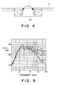
- the characteristics have no crests and valleys and that acoustic waves radiated from the dome-like vibrating plate causes neither reflection nor refraction.
- the features of the directionality are that the 30° characteristic exhibits substantially the same curve as the 0° characteristic and that the level difference is 3 - 4 dB, which is large on average compared to that between the characteristics obtained when the flat baffle 2 shown in Fig. 4 is used. This tendency is applicable to the 60° characteristics.
- the spherical wave horn baffle is an excellent one which satisfies both opposing matters of irrelevance to the hearing position and excellent location or positioning of an acoustic image.
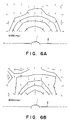
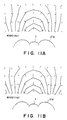
- Figs. 11A and 11B show the results using acoustic intensities in order to see the state of acoustic waves in the vicinity of a dome-like vibrating plate. Comparison of Figs. 11A and 11B and Figs. 6A and 6B exhibits that disturbances in the wave front of Figs. 11A and 11B are extremely small even at a position remote from the dome-like vibrating plate 1 compared to Figs. 6A and 6B.
- the dome-like speaker provides the flat characteristics, and improves the directional characteristic, and the location of an acoustic image by employing the new spherical wave horn baffle in the speaker.
- the horn baffle of Figs. 7 and 9 has a very excellent shape for a dome-like speaker to radiate acoustic waves without causing reflection, interference and refraction.
- Such structure of Fig. 13 serves to decrease disturbances in the acoustic waves due to reflection and refraction in the frequency characteristic.
- the object of this invention is to solve the above problems, and to provide a dome-like speaker in which the horn wall of the spherical wave horn baffle and the flat baffle surface of the cabinet are joined to each other without any discontinuity portion therebetween to thereby improve the frequency characteristic and acoustic quality.
- a dome-like speaker according to this invention solves the problems by forming a slope on a spherical wave horn baffle provided on the outer periphery of the dome-like vibrating plate and joining the slope to the flat baffle surface of the cabinet so as not to produce any discontinuity portions with the flat baffle surface.
- the baffle By the slope continuous to the horn wall of the spherical wave horn baffle provided on the dome-like speaker, the baffle can be joined to the flat baffle surface with no or little discontinuity portions to make it difficult to cause reflection and refraction of acoustic waves and provide a smooth frequency characteristic.
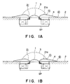
- Figs. 1 - 3 show embodiments of a dome-like speaker according to this invention.
- Fig. 1A is a cross section view of the essential portion of a first embodiment
- Fig. 1B is cross section view of the essential portion of a second embodiment
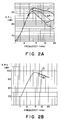
- Figs. 2A and 2B show frequency characteristics
- Figs. 3A and 3B show characteristics illustrating the state of acoustic waves in the vicinity of the dome-like vibrating plate.
- Figs. 4 - 13 show a conventional speaker.
- Fig. 4 is a cross section view of the essential portion of a structure in which the dome-like speaker is mounted on the flat baffle of the cabinet
- Fig. 5 is a frequency characteristic diagram
- FIGS. 6A and 6B are characteristic diagrams showing the state of acoustic waves in the vicinity of the dome-like vibrating plate
- Fig. 7 illustrates the principle of a spherical wave horn baffle
- Fig. 8 illustrates a change in the size of a baffle required when the cut off frequency of the dome-like vibrating plate varies
- Fig. 9 is a cross section view of the essential portion of a high-frequency band reproducing dome-like speaker which employs a spherical wave horn baffle
- Fig. 10 is a frequency characteristic diagram
- Figs. 11A and 11B are characteristic diagrams showing the state of acoustic waves in the vicinity of the dome-like vibrating plate of Fig. 9, Fig.
- Fig. 12 is a cross section view of the essential portion of a dome-like speaker having a spherical wave horn baffle mounted on the flat baffle of the cabinet
- Fig. 13 is a cross section view of the essential portion of an example which a spherical wave horn baffle is joined to the flat baffle surface of the cabinet.
- Fig. 1A is a cross section view of the essential portion of a first embodiment of this invention and Fig. 1B is a cross section view of the essential portion of a second embodiment.
- Figs. 2A and 2B are frequency characteristic diagrams and Figs. 3A and 3B show the state of acoustic waves in the vicinity of the dome-like vibrating plate using acoustic intensities at 6320 and 8000 Hz.
- a spherical horn baffle 21 provided on the dome-like speaker SP is mounted on the surface of a flat baffle 2 of the cabinet, they are not simply joined as shown in Fig. 12, but the baffle 2 surface and the horn wall 21a are continuously joined through a slope 4.
- the slope 4 is formed such that the tangent line at an end point c on the spherical wave horn baffle is smoothly connected to the surface of the flat baffle 2 at a point d without discontinuity.
- Reference numeral 3 inFigs. 1A and 1B denotes the front surface of the opening in the horn 21.
- the frequency and directional characteristics of the speaker do not substantially show disturbances, as shown in Fig. 2A.
- the relationship between the 30° and 60° characteristics and the 0° level is substantially similar to that of Fig. 10 and sufficiently maintains the closed characteristic of Fig. 7.
- This embodiment shows a structure in which the slope 4 which comprises an extension of a tangent line to the horn wall 21a of the spherical wave horn baffle 21 mounted on the dome-like speaker SP and the surface of the flat baffle 2 of the cabinet on which a dome-like speaker SP is mounted are joined with a discontinuity portion or a step at g therebetween.
- the rise or discontinuity portion at the junction g is formed to be sufficiently small compared to the wavelengths in the frequency band used of the speaker SP.
- the influence of reflection and refraction of acoustic waves by a discontinuity portion at the junction where the spherical wave horn baffle mounted on the dome-like speaker is joined to the flat baffle surface of the cabinet in which the speaker is mounted is reduced, so that disturbances in the frequency characteristic are greatly reduced and the acoustic quality is improved.
- the horn length can be increased compared to that of Fig. 13, so that the effect of the spherical wave horn baffle is improved.
- the dome-like vibrating plate can be disposed further forwardly compared to that of Fig. 13, so that the inventive structure is very preferable in acoustic characteristic.
- dome-like speaker having the spherical wave horn baffle can be easily mounted on the flat baffle surface of the cabinet to thereby improve greatly the characteristic of the speaker.
Landscapes
- Health & Medical Sciences (AREA)
- Otolaryngology (AREA)
- Physics & Mathematics (AREA)
- Engineering & Computer Science (AREA)
- Acoustics & Sound (AREA)
- Signal Processing (AREA)
- Obtaining Desirable Characteristics In Audible-Bandwidth Transducers (AREA)
Claims (2)
- Kalottenartiger Lautsprecher mit einer zur Ausbreitung von einer kalottenartigen Schwingungsplatte (1) ausgehender Schallwellen in einen Schallfeldraum hinein ohne Störung der Kugelwellen geformten Kugelwellen-Hornschallwand (21) aufgrund der Tatsache, daß von einer kalottenartigen Schwingungsplatte (1) ausgehende Schallwellen Kugelwellen ähnlich sind, dadurch gekennzeichnet, daß die Kugelwellen-Hornschallwand (21) eine Rampe (4) aufweist, die in einem Bereich flach und geneigt ist, wobei die Rampe (4) an eine flache Schallwandoberfläche (2) eines Lautsprechergehäuses anschließt und die Rampe (4) derart an die Schallwandoberfläche (2) anschließt, daß kein Unstetigkeitsbereich auftritt.
- Kalottenartiger Lautsprecher mit einer zur Ausbreitung von einer kalottenartigen Schwingungsplatte (1) ausgehender Schallwellen in einen Schallfeldraum hinein ohne Störung der Kugelwellen geformten Kugelwellen-Hornschallwand (21) aufgrund der Tatsache, daß von einer kalottenartigen Schwingungsplatte (1) ausgehende Schallwellen Kugelwellen ähnlich sind, dadurch gekennzeichnet, daß die Kugelwellen-Hornschallwand (21) eine flache und geneigte Rampe (4) aufweist, die an eine flache Schallwandoberfläche (2) eines Lautsprechergehäuses anschließt, und daß ein an der Verbindungsstelle der Rampe (4) und der Schallwandoberfläche (2) gebildeter Unstetigkeitsbereich (g) im Vergleich zu den Wellenlängen in einer Wiedergabezone der kalottenartigen Schwingungsplatte (1) hinreichend klein ausgebildet ist.
Applications Claiming Priority (2)
| Application Number | Priority Date | Filing Date | Title |
|---|---|---|---|
| JP190171/87 | 1987-07-31 | ||
| JP62190171A JP2588205B2 (ja) | 1987-07-31 | 1987-07-31 | ド−ム型スピ−カ |
Publications (3)
| Publication Number | Publication Date |
|---|---|
| EP0301552A2 EP0301552A2 (de) | 1989-02-01 |
| EP0301552A3 EP0301552A3 (en) | 1990-12-12 |
| EP0301552B1 true EP0301552B1 (de) | 1994-06-01 |
Family
ID=16253616
Family Applications (1)
| Application Number | Title | Priority Date | Filing Date |
|---|---|---|---|
| EP19880112256 Expired - Lifetime EP0301552B1 (de) | 1987-07-31 | 1988-07-28 | Kalottenähnliches Lautsprechersystem |
Country Status (3)
| Country | Link |
|---|---|
| EP (1) | EP0301552B1 (de) |
| JP (1) | JP2588205B2 (de) |
| DE (2) | DE3889798T2 (de) |
Families Citing this family (1)
| Publication number | Priority date | Publication date | Assignee | Title |
|---|---|---|---|---|
| KR101011087B1 (ko) * | 2008-08-14 | 2011-01-27 | 배익건 | 귀이개를 부설한 필기구 |
Family Cites Families (1)
| Publication number | Priority date | Publication date | Assignee | Title |
|---|---|---|---|---|
| DE2143539B2 (de) * | 1971-08-31 | 1974-12-19 | Gottlob Widmann + Soehne Gmbh, 7914 Pfuhl | Elektrodynamischer Lautsprecher für mittlere und hohe Frequenzen |
-
1987
- 1987-07-31 JP JP62190171A patent/JP2588205B2/ja not_active Expired - Fee Related
-
1988
- 1988-07-28 DE DE19883889798 patent/DE3889798T2/de not_active Expired - Fee Related
- 1988-07-28 EP EP19880112256 patent/EP0301552B1/de not_active Expired - Lifetime
- 1988-07-28 DE DE1988112256 patent/DE301552T1/de active Pending
Also Published As
| Publication number | Publication date |
|---|---|
| JPS6436193A (en) | 1989-02-07 |
| DE3889798D1 (de) | 1994-07-07 |
| DE301552T1 (de) | 1989-06-01 |
| DE3889798T2 (de) | 1995-01-05 |
| EP0301552A3 (en) | 1990-12-12 |
| JP2588205B2 (ja) | 1997-03-05 |
| EP0301552A2 (de) | 1989-02-01 |
Similar Documents
| Publication | Publication Date | Title |
|---|---|---|
| US5446792A (en) | Reflection-type speaker apparatus | |
| US6118883A (en) | System for controlling low frequency acoustical directivity patterns and minimizing directivity discontinuities during frequency transitions | |
| KR0132198B1 (ko) | 텔레비전 세트의 스피커 시스템 | |
| US8175311B2 (en) | Electroacoustic waveguide transducing | |
| US7236606B2 (en) | Sound system having a HF horn coaxially aligned in the mouth of a midrange horn | |
| JPS6081999A (ja) | ホ−ン型ラウドスピ−カ | |
| US4469921A (en) | Horn type loudspeaker | |
| US5115883A (en) | Loudspeaker | |
| JPH05268690A (ja) | 広角度の指向性を有するスピーカ装置 | |
| JP4123046B2 (ja) | スピーカ装置 | |
| US6585077B2 (en) | Sound-producing device with acoustic waveguide | |
| JPH09149487A (ja) | 電気音響変換システム | |
| JP2713080B2 (ja) | 指向性スピーカ装置 | |
| EP1292170B1 (de) | Anordnung zum Verhindern der Bildung von stehenden Wellen in einem Mobilfunkgerät | |
| US4454927A (en) | Reentrant cone driven loudspeaker | |
| EP0301552B1 (de) | Kalottenähnliches Lautsprechersystem | |
| JP2973677B2 (ja) | 反射型指向性スピーカ | |
| CN221381162U (zh) | 一种高音波导及包含该波导的高音号角和音箱 | |
| JPS6121917Y2 (de) | ||
| CN101283622A (zh) | 波导单元 | |
| US4445227A (en) | Loudspeaker having improved directional characteristics | |
| JPH04167697A (ja) | スピーカーシステム | |
| US8254614B2 (en) | Horn speaker with hyperbolic paraboloid lens | |
| CN117202051B (zh) | 一种双声源波前不共腔水平耦合高音波导 | |
| JPH05236585A (ja) | スピーカシステム |
Legal Events
| Date | Code | Title | Description |
|---|---|---|---|
| PUAI | Public reference made under article 153(3) epc to a published international application that has entered the european phase |
Free format text: ORIGINAL CODE: 0009012 |
|
| AK | Designated contracting states |
Kind code of ref document: A2 Designated state(s): DE FR GB |
|
| EL | Fr: translation of claims filed | ||
| DET | De: translation of patent claims | ||
| PUAL | Search report despatched |
Free format text: ORIGINAL CODE: 0009013 |
|
| AK | Designated contracting states |
Kind code of ref document: A3 Designated state(s): DE FR GB |
|
| 17P | Request for examination filed |
Effective date: 19910610 |
|
| RAP1 | Party data changed (applicant data changed or rights of an application transferred) |
Owner name: KABUSHIKI KAISHA KENWOOD |
|
| 17Q | First examination report despatched |
Effective date: 19930415 |
|
| GRAA | (expected) grant |
Free format text: ORIGINAL CODE: 0009210 |
|
| AK | Designated contracting states |
Kind code of ref document: B1 Designated state(s): DE FR GB |
|
| REF | Corresponds to: |
Ref document number: 3889798 Country of ref document: DE Date of ref document: 19940707 |
|
| ET | Fr: translation filed | ||
| RAP4 | Party data changed (patent owner data changed or rights of a patent transferred) |
Owner name: KABUSHIKI KAISHA KENWOOD |
|
| PLBE | No opposition filed within time limit |
Free format text: ORIGINAL CODE: 0009261 |
|
| STAA | Information on the status of an ep patent application or granted ep patent |
Free format text: STATUS: NO OPPOSITION FILED WITHIN TIME LIMIT |
|
| 26N | No opposition filed | ||
| REG | Reference to a national code |
Ref country code: GB Ref legal event code: IF02 |
|
| PGFP | Annual fee paid to national office [announced via postgrant information from national office to epo] |
Ref country code: GB Payment date: 20040716 Year of fee payment: 17 |
|
| PGFP | Annual fee paid to national office [announced via postgrant information from national office to epo] |
Ref country code: FR Payment date: 20040726 Year of fee payment: 17 |
|
| PGFP | Annual fee paid to national office [announced via postgrant information from national office to epo] |
Ref country code: DE Payment date: 20040930 Year of fee payment: 17 |
|
| PG25 | Lapsed in a contracting state [announced via postgrant information from national office to epo] |
Ref country code: GB Free format text: LAPSE BECAUSE OF NON-PAYMENT OF DUE FEES Effective date: 20050728 |
|
| PG25 | Lapsed in a contracting state [announced via postgrant information from national office to epo] |
Ref country code: DE Free format text: LAPSE BECAUSE OF NON-PAYMENT OF DUE FEES Effective date: 20060201 |
|
| GBPC | Gb: european patent ceased through non-payment of renewal fee |
Effective date: 20050728 |
|
| PG25 | Lapsed in a contracting state [announced via postgrant information from national office to epo] |
Ref country code: FR Free format text: LAPSE BECAUSE OF NON-PAYMENT OF DUE FEES Effective date: 20060331 |
|
| REG | Reference to a national code |
Ref country code: FR Ref legal event code: ST Effective date: 20060331 |