EP0301367B1 - Appareil d'arrosage - Google Patents
Appareil d'arrosage Download PDFInfo
- Publication number
- EP0301367B1 EP0301367B1 EP88111564A EP88111564A EP0301367B1 EP 0301367 B1 EP0301367 B1 EP 0301367B1 EP 88111564 A EP88111564 A EP 88111564A EP 88111564 A EP88111564 A EP 88111564A EP 0301367 B1 EP0301367 B1 EP 0301367B1
- Authority
- EP
- European Patent Office
- Prior art keywords
- nozzle
- nozzle unit
- head
- sprinkler according
- unit
- Prior art date
- Legal status (The legal status is an assumption and is not a legal conclusion. Google has not performed a legal analysis and makes no representation as to the accuracy of the status listed.)
- Expired - Lifetime
Links
Images

Classifications
-
- B—PERFORMING OPERATIONS; TRANSPORTING
- B05—SPRAYING OR ATOMISING IN GENERAL; APPLYING FLUENT MATERIALS TO SURFACES, IN GENERAL
- B05B—SPRAYING APPARATUS; ATOMISING APPARATUS; NOZZLES
- B05B3/00—Spraying or sprinkling apparatus with moving outlet elements or moving deflecting elements
- B05B3/02—Spraying or sprinkling apparatus with moving outlet elements or moving deflecting elements with rotating elements
- B05B3/04—Spraying or sprinkling apparatus with moving outlet elements or moving deflecting elements with rotating elements driven by the liquid or other fluent material discharged, e.g. the liquid actuating a motor before passing to the outlet
- B05B3/06—Spraying or sprinkling apparatus with moving outlet elements or moving deflecting elements with rotating elements driven by the liquid or other fluent material discharged, e.g. the liquid actuating a motor before passing to the outlet by jet reaction, i.e. creating a spinning torque due to a tangential component of the jet
-
- B—PERFORMING OPERATIONS; TRANSPORTING
- B05—SPRAYING OR ATOMISING IN GENERAL; APPLYING FLUENT MATERIALS TO SURFACES, IN GENERAL
- B05B—SPRAYING APPARATUS; ATOMISING APPARATUS; NOZZLES
- B05B1/00—Nozzles, spray heads or other outlets, with or without auxiliary devices such as valves, heating means
- B05B1/14—Nozzles, spray heads or other outlets, with or without auxiliary devices such as valves, heating means with multiple outlet openings; with strainers in or outside the outlet opening
- B05B1/16—Nozzles, spray heads or other outlets, with or without auxiliary devices such as valves, heating means with multiple outlet openings; with strainers in or outside the outlet opening having selectively- effective outlets
- B05B1/1627—Nozzles, spray heads or other outlets, with or without auxiliary devices such as valves, heating means with multiple outlet openings; with strainers in or outside the outlet opening having selectively- effective outlets with a selecting mechanism comprising a gate valve, a sliding valve or a cock
- B05B1/1672—Nozzles, spray heads or other outlets, with or without auxiliary devices such as valves, heating means with multiple outlet openings; with strainers in or outside the outlet opening having selectively- effective outlets with a selecting mechanism comprising a gate valve, a sliding valve or a cock the selectively-effective outlets being arranged on a tube or pipe
-
- B—PERFORMING OPERATIONS; TRANSPORTING
- B05—SPRAYING OR ATOMISING IN GENERAL; APPLYING FLUENT MATERIALS TO SURFACES, IN GENERAL
- B05B—SPRAYING APPARATUS; ATOMISING APPARATUS; NOZZLES
- B05B15/00—Details of spraying plant or spraying apparatus not otherwise provided for; Accessories
- B05B15/60—Arrangements for mounting, supporting or holding spraying apparatus
- B05B15/62—Arrangements for supporting spraying apparatus, e.g. suction cups
- B05B15/625—Arrangements for supporting spraying apparatus, e.g. suction cups designed to be placed on the ground
Definitions
- the invention relates to a sprinkling device according to the preamble of patent claim 1.
- a known irrigation device according to FR-A-1 319 379 has nozzle heads which are adjustable to change the atomization angle. As a result, however, the mode of operation of the irrigation device can be influenced only very slightly, and no adaptation in the sense of very different irrigation images is possible.
- the invention has for its object to provide a sprinkling device of the type mentioned, which allows the setting of very different sprinkling patterns in a simple manner, for example between one can choose between a small and an extremely large irrigation width or between a low and large irrigation density.
- At least one nozzle carrier at least two separate different nozzle units can be provided, at least one of which is arranged to be convertible into a rest position either in the working position and out of the working position.
- at least two nozzle units designed for different irrigation patterns can optionally be used, it being conceivable to design the nozzle units interchangeably, for example by plugging them onto the nozzle holder, so that the nozzle unit not required is separated from the nozzle holder, for example in a holder on the foot part can be kept.
- a particularly advantageous embodiment of the subject matter of the invention is that in addition to, but in particular instead, all the nozzle units provided for use on the associated nozzle holder are mounted on the nozzle holder in such a way that they can be moved separately or optionally in pairs or in pairs in a simple movement a working position can be transferred in which they are connected to the water supply. It can be provided two, four, five, six or more nozzle units, but preferably three nozzle units evenly distributed around an actuating axis, so that in the manner of a Turret control by turning the nozzle head can bring any of the existing nozzle units into the working position without any special effort and the associated irrigation pattern can be set.
- outlet nozzles for each nozzle unit in a row, for example, parallel to the actuating axis, so that a kind of flat water curtain can emerge from the differently inclined outlet nozzles of the nozzle unit.
- nozzles on an upright or approximately vertically arranged nozzle carrier, in most cases a more horizontal arrangement of the nozzle carrier is to be provided such that the nozzle unit is in the working position on the top of the nozzle carrier and the outlet nozzles of the row of nozzles take place are provided one behind the other in the associated orientation.
- the combination of the separate nozzle units brought into the working position results in numerous possible variations even for a very fine change of the irrigation pattern within a very large setting range.
- This can also be further improved in that the respective nozzle unit in the working position can be changed in position within a limited range relative to the nozzle carrier, which can be achieved in a particularly simple manner if the nozzle unit moves over a limited arc angle without interrupting the water supply can be adjusted about the adjustment axis and is only blocked when this arc angle is exceeded by the water supply.
- the arrangement can also be such that the water supply can be shut off per nozzle head, that is to say against all of its nozzle units is what z. B. can be achieved in that the water supply to both of these nozzle units is interrupted in a middle position between two working positions of two adjacent nozzle units. Shutting off or stopping individual nozzle heads increases the possible variations for setting the irrigation pattern accordingly by a multiple. This also applies if each nozzle unit is formed by an exchangeable nozzle body and all nozzle bodies are fastened to the nozzle head with the same fastening means, since in this case there are even more nozzle units to choose from than are provided on the nozzle heads.
- nozzle holder (s) in a fixed position relative to the foot part formed, for example, by an earth anchor, a standing console or the like, a particularly advantageous embodiment results if at least one, in particular all, nozzle holders are provided together on a rotor which has a suitable drive device rotates about a rotor axis during operation of the irrigation device, so that an even more uniform irrigation pattern is achieved over a relatively large irrigation area.
- nozzle carrier (s) for example reciprocating movements.
- the movement mentioned is expediently driven by hydropower via the pressurized water supplied to the sprinkling device, a separate water motor, such as a turbine, which is also conceivable, if at least one nozzle unit can be brought into an inclined drive position in such a way that it is simultaneously used as a drive nozzle acts, so the driving force for the nozzle holder is a reaction force of the water emerging from the nozzle unit.
- the irrigation device can be designed very simply and, in addition, the driving force can be changed between a maximum value and a preferably zero value by varying the setting of the nozzle unit in the working position, so that the variation in the movement speed of the nozzle holder results in a further increase in the possible variations of the irrigation pattern .
- three nozzle supports projecting in a star shape from an axis or the rotor axis, distributed uniformly around the axis and projecting to the same extent or having the same design are provided with the same nozzle heads, each nozzle head having three nozzle units each with a different number of outlet nozzles .
- the number of outlet nozzles per nozzle unit is expediently between approximately 1 or 2 and 10, preferably between 4 and 6, the outlet nozzles per nozzle unit having different nozzle widths and / or different nozzle inclination angles, in particular in such a way that the outermost outlet nozzle of the nozzle unit is the flattest Inclination angle or the largest nozzle width and the innermost outlet nozzle has the smallest nozzle width or the smallest angle of inclination, namely, for example, can be aligned approximately vertically; the intermediate outlet nozzles can have increasing angles of inclination in the direction of the outermost outlet nozzle.
- the arrangement is expediently such that the outermost outlet nozzles of all nozzle units have approximately the same distances relative to one end of the nozzle carrier or to the rotor axis, so that, depending on the number of outlet nozzles, the innermost outlet nozzles of the nozzle units have different corresponding distances.
- the intermediate distances between adjacent outlet nozzles are expediently the same for all nozzle units.
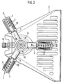
- the irrigation device 1 has a flat, desk-shaped and essentially trapezoidal foot part 2 in plan view, three star-shaped lying on its top, horizontal or to the standing area of the base part 2 approximately parallel nozzle holder 3, at the end of each nozzle holder 3 a nozzle head 4 rotatably mounted on a bearing shaft 5 about the central axis of the associated nozzle holder 3 and on each nozzle head 4 three nozzle units 6, 7 which are uniformly distributed over the circumference but differ from one another.
- each nozzle unit 6, 7, 8 being formed by a nozzle body 10, which is a separate, angular strip-shaped unit on the sleeve-shaped or sleeve-shaped nozzle head 4 via a snap or Plug connection is attached.
- the nozzle holder 3 are part of a rotor shaft 12, which is rotatable about a perpendicular or approximately vertical rotor axis 12 to the base of the foot part 2 and is located on the upper side close to the trapezoidal apex, which has a hub 13, which is only open at the bottom and with which the tubular nozzle carrier 3 are formed in one piece such that they protrude radially from the jacket of the hub 13. It is also conceivable to provide only a single nozzle holder 3 with a nozzle head 4.
- the hub 13 is rotatably mounted with a substantially spaced within its shell central, tubular and at an angle to the inner ends of the nozzle holder 3 bearing socket on a bearing sleeve 14 designed in the manner of a union nut, which on the external thread one over the top of the remaining foot part 2 protruding support neck 15 is screwed.
- the tubular support stub 15 merges in the interior of the foot part 2 into an angularly adjoining connection stub 16, which protrudes rearward beyond the apex surface of the trapezoidal shape and is designed to connect the hose coupling of a water hose.
- the support stub 15, the connection stub 16, the bearing stub and the respective nozzle carrier 3 including the associated bearing shaft 5 each form a water supply 17 for the associated nozzle head.
- the rotor 11 which is rotatably mounted via an axial sliding bearing, has a frustoconical bearing surface at the lower end of the bearing socket, to which a corresponding frustoconical bearing recess is assigned in the bearing sleeve 14.
- a bearing sleeve 19 is inserted, which has a collar on an end face of the bearing face 14 facing away from the bearing neck for receiving a bearing ring 20 which is also suitable for sealing and which, with axial play on its side facing the bearing neck, is assigned an annular surface of the bearing sleeve 14 as a running surface is.
- the storage described lies essentially within the projecting part of the support stub 15.
- all parts can be made of plastic or formed by injection molded plastic parts, but the bearing sleeve 19 is expediently made of thin-walled stainless steel.
- the design described results in a compact, smooth-running and dirt-protected bearing for the rotor 11.
- the bearing shaft 5 forms a continuation of the tubular nozzle carrier 3, which is closed at the free end at the front end, and is rigidly fastened to it by insertion with an end sleeve 21, whereby, however, possibly by twisting or by arrangement of the bearing shaft 5 offset according to the central axis of the nozzle carrier 3 in accordance with Art a basic adjustment the working position the respective nozzle unit can be influenced.
- the protruding part of the bearing shaft 5 has an outer width which is at most as large as the inner width of the nozzle carrier 3, in particular slightly smaller.
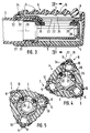
- a water passage opening 22 which is continuous over the major part of its length and which is elongated in view and which in the jacket of the nozzle head 4 has an approximately the same size or slightly longer and slightly narrower water inlet opening 23 for each nozzle unit 6 is assigned such that in at least one working position of the respective nozzle unit 6, its inlet opening 23 is practically congruent with the passage opening 22.
- the water inlet opening 23 directly adjoins a distribution chamber 24 which is longer or protrudes beyond the front and rear ends and which is delimited on the side opposite the inlet opening 23 by the associated nozzle body 10 or on this side the inner openings of the outlet nozzles 9 has.
- the nozzle body 10 has a trapezoidal profile with an open base side, projecting plug-in members being provided on the profile legs, which can be inserted into groove-shaped receptacles 26 of the nozzle head 4 provided on both sides of the respective distribution chamber such that the profile legs of the nozzle body 10 with their longitudinal edges rest against the nozzle head 4 and with their outer surfaces form a practically continuous continuation of the associated outer surfaces of the nozzle head 4.
- each nozzle body 10 has an end leg that is perpendicular to the row of its outlet nozzles 9 and lies approximately in the plane of the free end of the nozzle head 4.
- the nozzle head 4 is also sleeve-shaped and, at its free or outer end, is closed at the end in the manner of a push-in sleeve which is rotatably mounted on the outer circumference of the outer end of the nozzle carrier 3 with a bearing end 27 facing away from its end wall and having an inner diameter which is enlarged. Close to the free end of the nozzle carrier 3, the nozzle head 4 is reduced in internal width, but is supported over the largest part of the length of the bearing shaft 5 in a contact-free manner or only via the seal 25.
- annular groove 28 is expediently provided immediately adjacent to the end on the outer circumference of the bearing shaft 5, into which an adjacent groove associated end of the inlet opening 23 engages lying cams 29 of the nozzle head 4.
- the jacket of the nozzle head 4 which has a polygonal outer cross section approximately corresponding to the number of nozzle units 6, 7, 8 and the nozzle units 6, 7, 8 in the region of the Has cross-sectional corners, a number of openings corresponding to the number of nozzle units 6, 7, 8 is provided, which form the inlet openings 23.
- the jacket of the nozzle head 4 is also provided on the outer circumference in each case with a recess which is delimited over the entire circumference and extends approximately from the front end to approximately the rear end of the nozzle head 4, that is to say into the longitudinal region of the end sleeve 21 or the associated end of the nozzle carrier 3 is sufficient and which forms the distribution chamber 24, which is also slightly wider than the inlet opening 23.
- the nozzle body 10 lies with its inner surface sealed over the entire circumference of this boundary, all inner openings of all outlet nozzles 9 of the associated nozzle unit 6, 7, 8 being provided between the front and rear ends of this boundary .
- the foremost or outermost outlet nozzle 9 is expediently located together with further adjacent nozzles directly in the region of the inlet opening 23, while at least one or two rear outlet nozzles 9 are provided behind the inlet opening 23 in the region of the outer end of the nozzle carrier 3, that is to say in the region of the bearing end 27 could be.
- each of the nozzle units 6, 7, 8 can optionally be divided into at least one Bring work position in which its inlet opening 23 is connected in the manner described to the passage opening 22 of the water supply 17.
- the outlet nozzles 9 have a drive angle of attack relative to the rotor axis 12 such that a drive occurs when the water exits the outlet nozzles 9 on the rotor 11 -Rotational force acts, which sets the rotor 11 in rotary motion.
- the central axes of the outlet nozzles 9 lying in a common axial plane 31 in the working position on the top of the nozzle head 4 are inclined in longitudinal view of the nozzle head 4 relative to the rotor axis 12 by an angle of attack which is expediently less than 30 ° in the middle working position or Is 20 °, preferably about 10 ° such that this angle of attack can be continuously increased to about twice, ie about 20 °.
- the angle of attack is equal to zero, ie. H. that the axial plane 31 is parallel to or in the rotor axis 12.
- the central axes of the outlet nozzles 9 appropriately cross or intersect the actuating axis 30, i. H. that the axial plane 31 coinciding with the longitudinal central plane of the distribution chamber 24 and the inlet opening 23 is also an axial plane of the actuating axis 30 and coincides with the longitudinal central plane of the passage opening 22 in the middle working position.
- a locking device 32 is provided, which is expediently designed so that it must be overcome in both working end positions of the respective nozzle unit 6, 7, 8, it being conceivable that to make it easier to find the middle one Working position is also provided for this an easily triggered, but noticeable detent.
- at least one protruding detent cam 33 is provided on the outer circumference of the nozzle carrier 3, and a ring of detent openings 34, which are provided for the setting of the respective nozzle unit 6, 7, 8, is assigned to the jacket of the nozzle head 4 or the bearing end 27 .
- each nozzle unit 6, 7, 8 two latching cams 33 offset from one another at a corresponding arc angle and for each nozzle unit 6, 7, 8, only one latching opening 34 can be provided, which is expediently used as an opening in the jacket of the bearing end 27 formed and on the outer periphery of the associated end of the nozzle body 10 is covered, so that no dirt can penetrate despite simple manufacture.
- the angular distances between the inlet openings 23 and their widths are coordinated with respect to the effective arc angle of the seal 25 such that the nozzle head 4 is also in a middle position between two middle working positions of two adjacent nozzle units 6, 7 , 8 can be set so that the inlet openings 23 of these two adjacent nozzle units are located on both sides outside of the seal 25, that is to say that all the nozzle units 6, 7, 8 of the nozzle head 4 are blocked off from the water supply 17 and no water emerges from any of the associated outlet nozzles 9 can.
- the multi-arm irrigation device can therefore be set from an operation in which any number less than the total number of its arms is effective.
- each nozzle unit 6 of each nozzle head 4 has a large number of, for example, six nozzle openings 9 distributed uniformly over the length of the nozzle body 10, a further nozzle unit 7, in contrast, a number of, for example, five outlet nozzles 9 reduced by at least one outlet nozzle, and finally the third nozzle unit 8 a further reduced number, for example four outlet nozzles 9.
- the adjusting axes 30 could also be provided in the side view according to FIG. 1 at an angle to the rotor axis 12, for example, in such a way that they are inclined downwards or upwards towards the free ends of the nozzle arms; in any case, however, it is expedient if the adjusting axes 30 lie transversely to the rotor axis 12.
Claims (12)
- Appareil d'arrosage (1) comprenant un pied (2) et au moins un support de buses (3) disposé sur ce pied et pouvant être déplacé notamment par la puissance de l'eau, sachant qu'est prévue au moins une tête de buses (4) comprenant une unité de buses (6, 7, 8) présentant une buse de sortie (9) et associée à un entraînement pour réaliser un mouvement de travail, caractérisé en ce qu'au moins une tête de buses (4) peut être réglée peur faire fonctionner, au choix, différentes unités de buses (6, 7, 8), et en ce qu'au moins une unité de buses (6, 7, 8) présente au moins deux buses de sortie (9).
- Appareil d'arrosage selon la revendication 1, caractérisé en ce que l'unité de buses (6, 7, 8) peut être déplacée par rapport au support de buses (3) d'au moins une position de travail raccordée au conduit d'alimentation d'eau (17), et en ce que sont prévues peur au moins un support de buses (3), de préférence, au moins deux unités de buses (6, 7, 8) différentes et séparées, dont au moins l'une est disposée en position de travail ou peut être déplacée de la position de travail dans une position de repos.
- Appareil selon la revendication 1 ou 2, caractérisé en ce qu'au moins deux ou toutes les unités de buses (6, 7, 8) sont disposées ensemble dans un support sur le support de buses (3) et sont disposées de manière à pouvoir être déplacées alternativement entre une position de travail et une position de repos, sachant que, de préférence, au moins deux ou toutes les unités de buses (6, 7, 8) sont prévues sur une tête de buses (4) commune.
- Appareil selon l'une des revendications précédentes, caractérisé en ce que l'unité de buses (6, 7, 8) est disposée de manière rotative autour d'un axe de réglage (30), et en ce que la tête de buses (4) est montée sur le support de buses (3), de préférence, comme une tourelle de manière à ce que chaque fois au moins une unité de buses (6, 7, 8) soit en position de travail et/ou au moins une unité de buses (6, 7, 8) soit en position de repos.
- Appareil selon l'une des revendications précédentes, caractérisé en ce que chaque unité de buses (6, 7, 8) est réalisée en tant que buse d'entraînement pour le support de buses (3) monté sur le pied (2) notamment de manière à pouvoir tourner autour d'un axe de rotor (12), et en ce que les unités de buses (6, 7, 8) présentent des buses de sortie (9) essentiellement disposées en une rangée qui diffèrent par leur nombre, leur taille ou leur position angulaire.
- Appareil selon l'une des revendications précédentes, caractérisé en ce que les buses de sortie (9) de chaque unité de buses (6, 7, 8) sont essentiellement situées dans un plan axial (31) commun, notamment approximativement dans un plan axial de l'axe de réglage (30) ou de l'axe du rotor (12), et/ou en ce que sont prévus plusieurs supports de buses (3) notamment identiques qui sont, de préférence, formés par des bras de buses tubulaires prévus sur un moyeu de rotor (13) commun et faisant saillie en forme d'étoile de l'axe du rotor (12).
- Appareil selon l'une des revendications précédentes, caractérisé en ce que chaque unité de buses (6, 7, 8) est constituée par un corps de buses (10) notamment essentiellement en forme de baguette, et en ce que de préférence tous les corps de buses (10) de la tête de buses (4) sont logés ou enfoncés par des assemblages à enclenchement dans des logements (26) de la tête de buses (4) qui sont tous réalisés de la même manière.
- Appareil selon l'une des revendications précédentes, caractérisé en ce que chaque unité de buses (6, 7, 8) peut être réglée par rapport au support de buses (3), de préférence en continu, sur plusieurs positions de travail autour de l'axe de réglage (30) notamment, et en ce que l'unité de buses (6, 7, 8) présente, dans sa position de travail centrale, de préférence une inclinaison d'entraînement telle qu'en position de travail extérieure, elle prenne une position de repos d'entaînement.
- Appareil selon l'une des revendications précédentes, caractérisé en ce que dans le conduit d'alimentation d'eau (17) menant à chaque unité de buses (6, 7, 8) est disposé un clapet anti-retour réalisé notamment comme un robinet-vanne, qui s'ouvre ou se ferme, de préférence, en fonction de la position de l'unité de buses (6, 7, 8) qui lui est associée.
- Appareil selon l'une des revendications précédentes, caractérisé en ce que le support de buses (3) présente une tige (5) tubulaire pour la tête de buses (4), comportant un orifice de passage pour l'eau (22) menant à chaque unité de buses (6, 7, 8) en position de travail, et en ce que la tête de buses (4) est montée, de préférence, sur l'extrémité du support de buses (3), au voisinage de la tige (5) dont l'enveloppe est traversée par l'orifice de passage (22), et présente pour chaque unité de buses (6, 7, 8) une chambre de distribution (24) qui, en position de travail, coïncide essentiellement avec l'orifice de passage (22) entouré par une garniture d'étanchéité (25).
- Appareil selon l'une des revendications précédentes, caractérisé en ce que pour une zone de travail de chaque unité de buses (6, 7, 8), qui inclut au moins une position de travail, est prévu un dispositif à crans à ressort qui est formé, de préférence, par au moins un mentonnet (33) sur le pourtour extérieur du support de buses (3) et par des crans (34) dans l'enveloppe de la tête de buses (4) en cuvette, sachant que les crans (34) sont recouverts notamment à l'extérieur par les corps de buses (10).
- Appareil selon l'une des revendications précédentes, caractérisé en ce que les unités de buses (6, 7, 8) sont disposées dans un support horizontal de manière à pouvoir être déplacées, sachant que l'axe de réglage (30) perpendiculaire à l'axe du rotor (12) est, de préférence, prévu approximativement horizontal.
Priority Applications (1)
| Application Number | Priority Date | Filing Date | Title |
|---|---|---|---|
| AT88111564T ATE98913T1 (de) | 1987-07-31 | 1988-07-19 | Beregnungsvorrichtung. |
Applications Claiming Priority (2)
| Application Number | Priority Date | Filing Date | Title |
|---|---|---|---|
| DE19873725384 DE3725384A1 (de) | 1987-07-31 | 1987-07-31 | Beregnungsvorrichtung |
| DE3725384 | 1987-07-31 |
Publications (3)
| Publication Number | Publication Date |
|---|---|
| EP0301367A2 EP0301367A2 (fr) | 1989-02-01 |
| EP0301367A3 EP0301367A3 (en) | 1990-01-24 |
| EP0301367B1 true EP0301367B1 (fr) | 1993-12-22 |
Family
ID=6332778
Family Applications (1)
| Application Number | Title | Priority Date | Filing Date |
|---|---|---|---|
| EP88111564A Expired - Lifetime EP0301367B1 (fr) | 1987-07-31 | 1988-07-19 | Appareil d'arrosage |
Country Status (6)
| Country | Link |
|---|---|
| US (1) | US4905903A (fr) |
| EP (1) | EP0301367B1 (fr) |
| JP (1) | JP2646242B2 (fr) |
| AT (1) | ATE98913T1 (fr) |
| AU (1) | AU603473B2 (fr) |
| DE (2) | DE3725384A1 (fr) |
Families Citing this family (28)
| Publication number | Priority date | Publication date | Assignee | Title |
|---|---|---|---|---|
| US5480102A (en) * | 1990-08-06 | 1996-01-02 | Shimano Inc. | Baitcasting reel |
| US5307993A (en) * | 1992-01-22 | 1994-05-03 | Melnor Industries, Inc. | Rotary sprinkler |
| US5305956A (en) * | 1992-08-03 | 1994-04-26 | Wang H | Oscillatory sprinkler |
| US5826797C1 (en) * | 1995-03-16 | 2001-04-03 | Carl L C Kah Iii | Operationally changeable multiple nozzles sprinkler |
| CA2166157C (fr) * | 1995-12-27 | 1999-06-29 | King-Yuan Wang | Structure d'arroseur rotatif pour l'irrigation de pelouses |
| US5746375A (en) * | 1996-05-31 | 1998-05-05 | Guo; Wen-Li | Sprayer device |
| DE19830861A1 (de) * | 1998-07-10 | 2000-01-13 | Gardena Kress & Kastner Gmbh | Verfahren zur Verstellung des Regnerbildes einer Beregnungsvorrichtung und Beregnungsvorrichtung |
| IL155053A (en) * | 2003-03-24 | 2012-12-31 | Moshe Lutzki | Revolving sprinkler |
| TWI268809B (en) * | 2005-05-13 | 2006-12-21 | Hin Cheng Hsin Entpr Co Ltd | A sprinkler structure with adjustable spraying style and rotation speed |
| US8291524B2 (en) * | 2005-12-20 | 2012-10-23 | S.C, Johnson & Son, Inc. | Clip for mounting a fluid delivery device |
| US20070240252A1 (en) * | 2005-12-20 | 2007-10-18 | Leonard Stephen B | Clip for mounting a fluid delivery device |
| US7607590B2 (en) | 2006-08-31 | 2009-10-27 | Melnor, Inc. | Oscillating sprinkler with adjustable spray width |
| US8684283B2 (en) * | 2009-05-01 | 2014-04-01 | Melnor, Inc. | Variable range sprinkler apparatus and variable range sprinkler pattern method |
| DE102009044215A1 (de) * | 2009-10-09 | 2011-04-28 | Gardena Manufacturing Gmbh | Regner |
| US10232395B2 (en) | 2010-07-19 | 2019-03-19 | Irrigreen, Inc. | Multi-nozzle rotary sprinkler |
| EP2595756B1 (fr) * | 2010-07-19 | 2021-09-01 | Irrigreen LLC | Arroseur rotatif à plusieurs buses |
| US9010660B2 (en) | 2011-06-13 | 2015-04-21 | Nelson Irrigation Corporation | Integrated sprinkler head multi-nozzle/shut-off system |
| CN102247939A (zh) * | 2011-07-12 | 2011-11-23 | 马建 | 一种可控角度和射程的灌溉装置 |
| EP2551022A1 (fr) | 2011-07-25 | 2013-01-30 | Nelson Irrigation Corporation | Système à buses multiples, à charge latérale linéaire d'arroseur |
| CN103567102A (zh) * | 2012-07-24 | 2014-02-12 | 苏州宏久航空防热材料科技有限公司 | 一种玻璃棉用粘结剂喷洒装置 |
| US10350619B2 (en) | 2013-02-08 | 2019-07-16 | Rain Bird Corporation | Rotary sprinkler |
| US9492832B2 (en) | 2013-03-14 | 2016-11-15 | Rain Bird Corporation | Sprinkler with brake assembly |
| US9669420B2 (en) * | 2013-03-15 | 2017-06-06 | Fiskars Oyj Abp | Water sprinkler |
| US9700904B2 (en) | 2014-02-07 | 2017-07-11 | Rain Bird Corporation | Sprinkler |
| EP3445145B1 (fr) | 2016-04-18 | 2023-07-12 | Precision Planting LLC | Outils et unités d'application ayant au moins un élément d'application pour la réalisation d'applications par rapport à des plantes agricoles de champs agricoles |
| RU2706291C1 (ru) | 2016-07-22 | 2019-11-15 | ПРЕСИЖН ПЛЭНТИНГ ЭлЭлСи | Орудия и устройства для нанесения для размещения вносимых материалов относительно сельскохозяйственных растений на сельскохозяйственных полях |
| CN106134932A (zh) * | 2016-08-08 | 2016-11-23 | 李海斌 | 柱状瞄准式节水灌溉系统 |
| DE102019114760A1 (de) * | 2019-06-03 | 2020-12-03 | Dr. Ing. H.C. F. Porsche Aktiengesellschaft | Vorrichtung zum Kühlen einer Unterbodenbatterie eines Kraftfahrzeugs und Verfahren zum Kühlen einer Unterbodenbatterie eines Kraftfahrzeugs |
Family Cites Families (13)
| Publication number | Priority date | Publication date | Assignee | Title |
|---|---|---|---|---|
| US2624625A (en) * | 1949-01-11 | 1953-01-06 | Crane Co | Shower head |
| US2769667A (en) * | 1954-07-22 | 1956-11-06 | Scovill Manufacturing Co | Reaction type sprinklers |
| US3051183A (en) * | 1959-03-30 | 1962-08-28 | Gen Motors Corp | Spray tube for a dishwasher |
| US3064665A (en) * | 1960-12-01 | 1962-11-20 | Gen Electric | Dishwashing apparatus |
| US3081950A (en) * | 1961-06-15 | 1963-03-19 | Melnor Ind Inc | Turret-type lawn sprinkler |
| FR1319379A (fr) * | 1962-01-17 | 1963-03-01 | Doyer Ets | Perfectionnements aux arroseurs rotatifs |
| US3459377A (en) * | 1967-11-14 | 1969-08-05 | Kenneth I Van Der Hulse | Sprinkler hose construction |
| FR2278404A1 (fr) * | 1974-07-19 | 1976-02-13 | Pont A Mousson | Deverseur, notamment sanitaire, a jets multiples |
| GB1492096A (en) * | 1975-09-16 | 1977-11-16 | Burnett & Rolfe Ltd | Device for cleaning storage tanks and like containers |
| DE2600071A1 (de) * | 1976-01-02 | 1977-07-14 | Sauter Fa Ernst | Brausekopf mit verstellbarem wasserstrahl |
| US3982698A (en) * | 1976-01-29 | 1976-09-28 | Specialty Manufacturing Company | Nozzle selector valve |
| US4510784A (en) * | 1983-10-11 | 1985-04-16 | Kaiser Aluminum & Chemical Corporation | Rolling mill spray bar |
| US4671462A (en) * | 1984-09-20 | 1987-06-09 | Gerardus Johannes Kraaij | Sprinklers |
-
1987
- 1987-07-31 DE DE19873725384 patent/DE3725384A1/de not_active Withdrawn
-
1988
- 1988-07-19 AT AT88111564T patent/ATE98913T1/de not_active IP Right Cessation
- 1988-07-19 EP EP88111564A patent/EP0301367B1/fr not_active Expired - Lifetime
- 1988-07-19 DE DE88111564T patent/DE3886464D1/de not_active Expired - Fee Related
- 1988-07-28 US US07/225,286 patent/US4905903A/en not_active Expired - Fee Related
- 1988-07-28 JP JP63187058A patent/JP2646242B2/ja not_active Expired - Lifetime
- 1988-07-29 AU AU20189/88A patent/AU603473B2/en not_active Ceased
Also Published As
| Publication number | Publication date |
|---|---|
| EP0301367A2 (fr) | 1989-02-01 |
| JPS6451161A (en) | 1989-02-27 |
| ATE98913T1 (de) | 1994-01-15 |
| AU603473B2 (en) | 1990-11-15 |
| EP0301367A3 (en) | 1990-01-24 |
| DE3886464D1 (de) | 1994-02-03 |
| US4905903A (en) | 1990-03-06 |
| AU2018988A (en) | 1989-02-02 |
| JP2646242B2 (ja) | 1997-08-27 |
| DE3725384A1 (de) | 1989-02-09 |
Similar Documents
| Publication | Publication Date | Title |
|---|---|---|
| EP0301367B1 (fr) | Appareil d'arrosage | |
| DE2819945C2 (de) | Gerät zum Versprühen von Flüssigkeit | |
| DE69723968T2 (de) | Auf vorgegebene sprühbilder einstellbarer statischer sprinkler | |
| EP0826426B1 (fr) | Arroseur | |
| DE2911405C2 (de) | Massagebrause mit einer Einrichtung zur wahlweisen Erzeugung pulsierender und/oder nicht pulsierender Flüssigkeitsstrahlen | |
| DE102011000344B4 (de) | Anordnung zur Verstellung der Düsen eines Sprinklers | |
| EP0698417B2 (fr) | Arroseur pour la distribution d'un fluide | |
| DE2901306C2 (fr) | ||
| DE2615111A1 (de) | Verstellbarer duschkopf | |
| DE4328303C2 (de) | Einrichtung zum Entzundern von warmem Walzgut | |
| DE2904127A1 (de) | Einstellbare fluessigkeitsabgabeduese | |
| DE3820080A1 (de) | Handbrause mit einem rotierenden buerstensatz | |
| EP0970753A2 (fr) | Méthode de régler le façon de distribution d'eau d'un arroseur et arroseur | |
| EP1343591B1 (fr) | Gicleur | |
| DE4133973C2 (de) | Vorrichtung zum Versprühen eines Flüssigkeitsstrahls mit rotierender Achse auf einer konischen Fläche | |
| EP0410198B1 (fr) | Arroseur escamotable | |
| DE1609199C (fr) | ||
| DE1609199A1 (de) | Brausekopf | |
| DE2412748B2 (de) | Beregnungsvorrichtung | |
| EP2181772B1 (fr) | Dispositif d'irrigation | |
| EP1502653B1 (fr) | Buse de pulvérisation d'un fluide sur une suface | |
| EP1000665A2 (fr) | Buse rotative | |
| EP0247532A2 (fr) | Dispositif de nettoyage pour réservoirs et similaires | |
| DE4109001C2 (fr) | ||
| EP0639325B1 (fr) | Distributeur de fluide, en particulier pour l'irrigation de sols |
Legal Events
| Date | Code | Title | Description |
|---|---|---|---|
| PUAI | Public reference made under article 153(3) epc to a published international application that has entered the european phase |
Free format text: ORIGINAL CODE: 0009012 |
|
| AK | Designated contracting states |
Kind code of ref document: A2 Designated state(s): AT CH DE FR GB IT LI NL SE |
|
| PUAL | Search report despatched |
Free format text: ORIGINAL CODE: 0009013 |
|
| AK | Designated contracting states |
Kind code of ref document: A3 Designated state(s): AT CH DE FR GB IT LI NL SE |
|
| 17P | Request for examination filed |
Effective date: 19900504 |
|
| 17Q | First examination report despatched |
Effective date: 19911001 |
|
| GRAA | (expected) grant |
Free format text: ORIGINAL CODE: 0009210 |
|
| AK | Designated contracting states |
Kind code of ref document: B1 Designated state(s): AT CH DE FR GB IT LI NL SE |
|
| REF | Corresponds to: |
Ref document number: 98913 Country of ref document: AT Date of ref document: 19940115 Kind code of ref document: T |
|
| ET | Fr: translation filed | ||
| GBT | Gb: translation of ep patent filed (gb section 77(6)(a)/1977) |
Effective date: 19940105 |
|
| REF | Corresponds to: |
Ref document number: 3886464 Country of ref document: DE Date of ref document: 19940203 |
|
| ITF | It: translation for a ep patent filed |
Owner name: MODIANO & ASSOCIATI S.R.L. |
|
| PG25 | Lapsed in a contracting state [announced via postgrant information from national office to epo] |
Ref country code: LI Effective date: 19940731 Ref country code: CH Effective date: 19940731 |
|
| PLBE | No opposition filed within time limit |
Free format text: ORIGINAL CODE: 0009261 |
|
| STAA | Information on the status of an ep patent application or granted ep patent |
Free format text: STATUS: NO OPPOSITION FILED WITHIN TIME LIMIT |
|
| 26N | No opposition filed | ||
| EAL | Se: european patent in force in sweden |
Ref document number: 88111564.6 |
|
| REG | Reference to a national code |
Ref country code: CH Ref legal event code: PL |
|
| REG | Reference to a national code |
Ref country code: GB Ref legal event code: IF02 |
|
| PGFP | Annual fee paid to national office [announced via postgrant information from national office to epo] |
Ref country code: NL Payment date: 20020717 Year of fee payment: 15 |
|
| PGFP | Annual fee paid to national office [announced via postgrant information from national office to epo] |
Ref country code: AT Payment date: 20020722 Year of fee payment: 15 |
|
| PGFP | Annual fee paid to national office [announced via postgrant information from national office to epo] |
Ref country code: SE Payment date: 20020723 Year of fee payment: 15 |
|
| PGFP | Annual fee paid to national office [announced via postgrant information from national office to epo] |
Ref country code: GB Payment date: 20030630 Year of fee payment: 16 |
|
| PG25 | Lapsed in a contracting state [announced via postgrant information from national office to epo] |
Ref country code: AT Free format text: LAPSE BECAUSE OF NON-PAYMENT OF DUE FEES Effective date: 20030719 |
|
| PG25 | Lapsed in a contracting state [announced via postgrant information from national office to epo] |
Ref country code: SE Free format text: LAPSE BECAUSE OF NON-PAYMENT OF DUE FEES Effective date: 20030720 |
|
| PG25 | Lapsed in a contracting state [announced via postgrant information from national office to epo] |
Ref country code: NL Free format text: LAPSE BECAUSE OF NON-PAYMENT OF DUE FEES Effective date: 20040201 |
|
| EUG | Se: european patent has lapsed | ||
| NLV4 | Nl: lapsed or anulled due to non-payment of the annual fee |
Effective date: 20040201 |
|
| PG25 | Lapsed in a contracting state [announced via postgrant information from national office to epo] |
Ref country code: GB Free format text: LAPSE BECAUSE OF NON-PAYMENT OF DUE FEES Effective date: 20040719 |
|
| GBPC | Gb: european patent ceased through non-payment of renewal fee |
Effective date: 20040719 |
|
| PG25 | Lapsed in a contracting state [announced via postgrant information from national office to epo] |
Ref country code: IT Free format text: LAPSE BECAUSE OF NON-PAYMENT OF DUE FEES Effective date: 20050719 |
|
| PGFP | Annual fee paid to national office [announced via postgrant information from national office to epo] |
Ref country code: FR Payment date: 20060719 Year of fee payment: 19 |
|
| PGFP | Annual fee paid to national office [announced via postgrant information from national office to epo] |
Ref country code: DE Payment date: 20060810 Year of fee payment: 19 |
|
| PG25 | Lapsed in a contracting state [announced via postgrant information from national office to epo] |
Ref country code: DE Free format text: LAPSE BECAUSE OF NON-PAYMENT OF DUE FEES Effective date: 20080201 |
|
| REG | Reference to a national code |
Ref country code: FR Ref legal event code: ST Effective date: 20080331 |
|
| PG25 | Lapsed in a contracting state [announced via postgrant information from national office to epo] |
Ref country code: FR Free format text: LAPSE BECAUSE OF NON-PAYMENT OF DUE FEES Effective date: 20070731 |