EP0294281B1 - System zum Halten von Tochtergeschossen in einem sich um seine Längsachse drehenden Geschoss - Google Patents
System zum Halten von Tochtergeschossen in einem sich um seine Längsachse drehenden Geschoss Download PDFInfo
- Publication number
- EP0294281B1 EP0294281B1 EP88401314A EP88401314A EP0294281B1 EP 0294281 B1 EP0294281 B1 EP 0294281B1 EP 88401314 A EP88401314 A EP 88401314A EP 88401314 A EP88401314 A EP 88401314A EP 0294281 B1 EP0294281 B1 EP 0294281B1
- Authority
- EP
- European Patent Office
- Prior art keywords
- stage
- tabs
- parts
- release
- tab
- Prior art date
- Legal status (The legal status is an assumption and is not a legal conclusion. Google has not performed a legal analysis and makes no representation as to the accuracy of the status listed.)
- Expired - Lifetime
Links
- 230000000694 effects Effects 0.000 claims description 4
- 230000002093 peripheral effect Effects 0.000 claims description 3
- 125000006850 spacer group Chemical group 0.000 description 21
- 230000000284 resting effect Effects 0.000 description 4
- 238000010586 diagram Methods 0.000 description 2
- 238000000605 extraction Methods 0.000 description 2
- 238000000034 method Methods 0.000 description 2
- 239000004570 mortar (masonry) Substances 0.000 description 2
- 238000000926 separation method Methods 0.000 description 2
- 230000001133 acceleration Effects 0.000 description 1
- 230000000712 assembly Effects 0.000 description 1
- 238000000429 assembly Methods 0.000 description 1
- 230000007423 decrease Effects 0.000 description 1
- 230000001788 irregular Effects 0.000 description 1
- 230000000750 progressive effect Effects 0.000 description 1
- 230000002787 reinforcement Effects 0.000 description 1
- 210000003462 vein Anatomy 0.000 description 1
Images

Classifications
-
- F—MECHANICAL ENGINEERING; LIGHTING; HEATING; WEAPONS; BLASTING
- F42—AMMUNITION; BLASTING
- F42B—EXPLOSIVE CHARGES, e.g. FOR BLASTING, FIREWORKS, AMMUNITION
- F42B12/00—Projectiles, missiles or mines characterised by the warhead, the intended effect, or the material
- F42B12/02—Projectiles, missiles or mines characterised by the warhead, the intended effect, or the material characterised by the warhead or the intended effect
- F42B12/36—Projectiles, missiles or mines characterised by the warhead, the intended effect, or the material characterised by the warhead or the intended effect for dispensing materials; for producing chemical or physical reaction; for signalling ; for transmitting information
- F42B12/56—Projectiles, missiles or mines characterised by the warhead, the intended effect, or the material characterised by the warhead or the intended effect for dispensing materials; for producing chemical or physical reaction; for signalling ; for transmitting information for dispensing discrete solid bodies
- F42B12/58—Cluster or cargo ammunition, i.e. projectiles containing one or more submissiles
- F42B12/62—Cluster or cargo ammunition, i.e. projectiles containing one or more submissiles the submissiles being ejected parallel to the longitudinal axis of the projectile
-
- F—MECHANICAL ENGINEERING; LIGHTING; HEATING; WEAPONS; BLASTING
- F42—AMMUNITION; BLASTING
- F42B—EXPLOSIVE CHARGES, e.g. FOR BLASTING, FIREWORKS, AMMUNITION
- F42B14/00—Projectiles or missiles characterised by arrangements for guiding or sealing them inside barrels, or for lubricating or cleaning barrels
- F42B14/06—Sub-calibre projectiles having sabots; Sabots therefor
-
- F—MECHANICAL ENGINEERING; LIGHTING; HEATING; WEAPONS; BLASTING
- F42—AMMUNITION; BLASTING
- F42B—EXPLOSIVE CHARGES, e.g. FOR BLASTING, FIREWORKS, AMMUNITION
- F42B14/00—Projectiles or missiles characterised by arrangements for guiding or sealing them inside barrels, or for lubricating or cleaning barrels
- F42B14/06—Sub-calibre projectiles having sabots; Sabots therefor
- F42B14/065—Sabots carrying several projectiles
Definitions
- the invention relates to loads composed of multiple and / or heterogeneous charges such as submunitions, loaded on a projectile rotating around its longitudinal axis. These loads having to be dropped during the trajectory, their arrangement inside the projectile is provided to separate the components at the time of their release.
- the invention is more particularly adapted to solve problems concerning the projectiles constituted by mortar shells, the rotational speed of which is very high (more than 10,000 revolutions per minute).
- each submunition has a support element, consisting of two spacers 2A and 2B, separable at the time of the release to release the submunition. These two spacers have at their rear a reinforcement 3A and 3B to support the submunition upon departure.
- the inertia forces at the start of the shot, due to each submunition are only supported by their two respective spacers. Each spacer is in contact with the next. The forces thus accumulated are transmitted to the bottom 4 of the projectile.
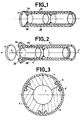
- FIG. 2 One of the drawbacks of this type of mounting is illustrated in FIG. 2. On this, the same elements have been shown as those shown in FIG. 1, but during the release. The ejection is done by the rear of the casing 5 of the projectile, along the longitudinal axis XX ′, the bottom 4 coming off first. Next follow, the last two spacers 2A and 2B supporting the ammunition 6. It can be seen that the rear parts 3A and 3B of the last two spacers are subjected to centrifugal force due to the high speed of rotation of the entire projectile, of the submunitions and their spacers.
- the object of the invention is to remedy these drawbacks by creating a new system for maintaining the load inside the projectile while allowing it to be released easily.
- the invention is a load holding system composed of multiple and / or heterogeneous charges loaded on a projectile rotating around its longitudinal axis and released during the trajectory by one end thereof, said load comprising at at least one stage comprising side by side at least two distinct parts which must be separated at the time of the release, the projectile comprising an envelope inside which said loading is placed, the system being characterized in that it comprises for each stage of the fixing means intended to maintain in a compact assembly the distinct parts of said stage, so as not to cause against the envelope significant radial stresses under the effect of the centrifugal force resulting from the rotation of the projectile, these fixing means consisting of U-shaped profiles called jumpers, placed on the periphery of each stage and having at least two fixing lugs, each of these lugs entering in a corresponding peripheral recess of one of said separate parts, the mechanical strength and the exact shape of said jumpers being provided so that they hold the parts of the same stage before release, and that they retract at the moment of the drop.
- the principle of the system according to the invention is based on the fact that the different parts of a stage of a stack, in this case the spacers 6 and their submunitions 7, must constitute a compact stage before dropping so as not to cause significant radial stresses against the envelope 5 due to the centrifugal force created by the projectile rotating around its longitudinal axis.
- Fastening means 8 must be provided, and also be retractable at the time of the release so that these different parts can move laterally and freely, due to the centrifugal force.
- these fixing means consists in using U-shaped profiles called, in the following description, "jumpers". These parts are rigid enough to hold the different parts of the same floor, and are placed on the periphery of the assembly. Referring to Figure 4, these jumpers have in their cross section, two legs 9, each sinking into a corresponding notch of one of the parts 6 to be maintained assemblies. These tabs are connected by a central part 10 of smaller thickness.
- the shape of the rider's legs is such that, under the influence of the centrifugal force, its components and the friction forces thus generated, all the riders and the parts linked by these riders remain naturally united. This can be done for example by forming a slight dovetail.
- the jumpers are each associated with ejection means.
- the latter are constituted, to operate under the effect of simple centrifugal force, counterweight 12, whose mass subjected to centrifugal force, allows the uprooting of a jumper. Furthermore, this mass should not be too large so that the centrifugal force, which is applied to it, does not cause the annoying friction against the casing 5, mentioned in connection with the devices according to known techniques.
- Each flyweight is associated with a rider. In FIG. 4, no fixing means between the rider and the counterweight has been drawn, the counterweight 12 being able to form an integral part of the rider 10. Fixing means can however be envisaged between these two parts, for example, means fixing by pins or screws placed parallel to the axis of the casing 5.
- this counterweight 12 is the last part of the jumper to come out of the envelope 5 (see FIG. 5).
- the flyweight drives the rider after an inward race.
- the counterweight 30 has an annular groove 31, deep enough to allow a re-entrant annular part 32 of the jumper 33 to penetrate therein over several millimeters while not filling a radial space E.
- the side 34 of the groove 31 placed between it and the rider has a reduced diameter to allow a translational movement of the counterweight 30 towards the outside, authorized by the presence of the space E.
- the counterweight is released from the envelope, it deviates towards the outside as previously.
- the jumper must be completely removed so that it can be ejected from the parts 6 to be separated. This therefore prevents the bracing of any part during its exit from the envelope.
- the separation of the parts, after the uprooting of all the jumpers, is carried out thanks to the centrifugal force which applies to each of the parts 6.
- the application of the system according to the invention to a projectile containing the submunitions is as follows.
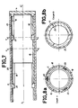
- the counterweights are of a thickness greater than that of the corresponding jumper 20, but also that these weights extend over a maximum peripheral sector, forming a continuous circular ring, so as to touch each other. This has the effect of considerably increasing the mass of these weights. By this fact, they can also provide support for the corresponding munition 6.
- the spacers 18 only position the submunitions coaxially. As shown in FIG.
- the counterweight 21 no longer fulfills the function of hooking the spacers 18, and is therefore subjected to centrifugal force without being maintained by the ammunition 6, this so as to entail, during the release, the remainder of the rider 20.
- the ammunition in this example was drawn in two parts of different diameter, and resting on the weights, approximately in the middle of the length of each ammunition. This is a exemplary embodiment, each munition being able to be supported either by the counterweight, or by the spacer, at one end of this ammunition as well as in its center.
- the spacers do not separate until after their complete extraction, and avoid jamming stresses by progressive angular separation during extraction, as illustrated in FIG. 5.
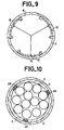
- FIGS. 8 and 9 can allow asymmetrical locking and release, so as to make variable lateral ejections of the different parts.
- the system easily allows the entire load placed inside the envelope to be rotated, by providing interconnection between each spacer.
Landscapes
- Engineering & Computer Science (AREA)
- General Engineering & Computer Science (AREA)
- Chemical & Material Sciences (AREA)
- Combustion & Propulsion (AREA)
- Aiming, Guidance, Guns With A Light Source, Armor, Camouflage, And Targets (AREA)
- Toys (AREA)
Claims (11)
Applications Claiming Priority (2)
| Application Number | Priority Date | Filing Date | Title |
|---|---|---|---|
| FR8707708A FR2616217B1 (fr) | 1987-06-02 | 1987-06-02 | Systeme de maintien de charges multiples embarquees dans un projectile tournant autour de son axe longitudinal |
| FR8707708 | 1987-06-02 |
Publications (2)
| Publication Number | Publication Date |
|---|---|
| EP0294281A1 EP0294281A1 (de) | 1988-12-07 |
| EP0294281B1 true EP0294281B1 (de) | 1992-01-29 |
Family
ID=9351669
Family Applications (1)
| Application Number | Title | Priority Date | Filing Date |
|---|---|---|---|
| EP88401314A Expired - Lifetime EP0294281B1 (de) | 1987-06-02 | 1988-05-31 | System zum Halten von Tochtergeschossen in einem sich um seine Längsachse drehenden Geschoss |
Country Status (4)
| Country | Link |
|---|---|
| US (1) | US4920887A (de) |
| EP (1) | EP0294281B1 (de) |
| DE (1) | DE3868144D1 (de) |
| FR (1) | FR2616217B1 (de) |
Families Citing this family (16)
| Publication number | Priority date | Publication date | Assignee | Title |
|---|---|---|---|---|
| FR2684754B1 (fr) * | 1991-12-10 | 1995-04-07 | Thomson Brandt Armements | Obus dont le culot fait office de pot de parachute d'une sous-munition. |
| SE503719C2 (sv) * | 1992-06-30 | 1996-08-12 | Bofors Ab | Sätt och anordning för separation av substridsdelar |
| DE4429292C2 (de) * | 1994-08-18 | 1998-04-09 | Rheinmetall Ind Ag | Drallstabilisiertes Trägergeschoß |
| KR100549487B1 (ko) * | 1997-12-11 | 2006-02-08 | 록히드 마틴 코포레이션 | 장갑형 투하 폭탄 |
| US6408762B1 (en) | 1997-12-11 | 2002-06-25 | Lockheed Martin Corporation | Clamp assembly for shrouded aerial bomb |
| US6389977B1 (en) | 1997-12-11 | 2002-05-21 | Lockheed Martin Corporation | Shrouded aerial bomb |
| RU2138007C1 (ru) * | 1998-09-07 | 1999-09-20 | Государственное научно-производственное предприятие "Сплав" | Кассетная головная часть |
| USD438930S1 (en) | 2000-02-09 | 2001-03-13 | Lockheed Martin | Shrouded aerial bomb |
| US6374744B1 (en) | 2000-05-25 | 2002-04-23 | Lockheed Martin Corporation | Shrouded bomb |
| US6874425B1 (en) | 2001-05-18 | 2005-04-05 | Day & Zimmermann, Inc. | Projectile carrying sub-munitions |
| US6640723B2 (en) * | 2002-03-25 | 2003-11-04 | The United States Of America As Represented By The Secretary Of The Navy | Mission responsive ordnance |
| US6619210B1 (en) * | 2002-03-25 | 2003-09-16 | The United States Of America As Represented By The Secretary Of The Navy | Explosively formed penetrator (EFP) and fragmenting warhead |
| US6857371B1 (en) * | 2003-06-19 | 2005-02-22 | The United States Of America As Represented By The Secretary Of The Navy | Two-payload decoy device |
| SE540399C2 (sv) | 2016-04-20 | 2018-09-11 | Bae Systems Bofors Ab | Stödanordning för delningsbar fallskärmsgranat |
| RU2681042C1 (ru) * | 2018-03-26 | 2019-03-01 | Акционерное общество "Конструкторское бюро приборостроения им. академика А.Г. Шипунова" | Отделяющееся ведущее устройство подкалиберного реактивного снаряда |
| US10443993B1 (en) * | 2018-11-29 | 2019-10-15 | The United States Of America As Represented By The Secretary Of The Army | Spin discarding multiple projectile sabot |
Family Cites Families (10)
| Publication number | Priority date | Publication date | Assignee | Title |
|---|---|---|---|---|
| US3016011A (en) * | 1956-07-11 | 1962-01-09 | Brown Fred | Cluster opening method |
| US2970542A (en) * | 1956-07-13 | 1961-02-07 | George L Pigman | Bomb release device |
| US3088404A (en) * | 1956-11-15 | 1963-05-07 | Brown Fred | Interlocking screw threads |
| US3834312A (en) * | 1973-03-14 | 1974-09-10 | Bofors Ab | Parachute-borne flare assemblage |
| US4389940A (en) * | 1976-04-02 | 1983-06-28 | Raytheon Company | Antipersonnel mine |
| DE3139473C2 (de) * | 1981-10-03 | 1984-03-01 | Diehl GmbH & Co, 8500 Nürnberg | Vorrichtung zum Zusammenfassen von zylindrischer Abwurfmunition in Bündeln |
| FR2547910B1 (fr) * | 1983-06-27 | 1987-01-23 | Lacroix E Tous Artifices | Projectile pour dispersion de munitions |
| DE3506889A1 (de) * | 1985-02-27 | 1986-08-28 | Dynamit Nobel Ag, 5210 Troisdorf | Flugkoerper |
| US4638737A (en) * | 1985-06-28 | 1987-01-27 | The United States Of America As Represented By The Secretary Of The Army | Multi-warhead, anti-armor missile |
| US4714020A (en) * | 1987-01-30 | 1987-12-22 | Honeywell Inc. | Enabling device for a gas generator of a forced dispersion munitions dispenser |
-
1987
- 1987-06-02 FR FR8707708A patent/FR2616217B1/fr not_active Expired - Fee Related
-
1988
- 1988-05-31 EP EP88401314A patent/EP0294281B1/de not_active Expired - Lifetime
- 1988-05-31 DE DE8888401314T patent/DE3868144D1/de not_active Expired - Fee Related
- 1988-06-03 US US07/201,853 patent/US4920887A/en not_active Expired - Lifetime
Also Published As
| Publication number | Publication date |
|---|---|
| FR2616217B1 (fr) | 1993-02-05 |
| DE3868144D1 (de) | 1992-03-12 |
| FR2616217A1 (fr) | 1988-12-09 |
| US4920887A (en) | 1990-05-01 |
| EP0294281A1 (de) | 1988-12-07 |
Similar Documents
| Publication | Publication Date | Title |
|---|---|---|
| EP0294281A1 (de) | System zum Halten von Tochtergeschossen in einem sich um seine Längsachse drehenden Geschoss | |
| EP0541411B1 (de) | Vorrichtung zum Auswerfen der Submunitionen aus einem Trägergeschoss | |
| EP3102906B1 (de) | Hohlladung und verwendung zur trennung von zwei stockwerken eines luftfahrtfahrzeugs oder zur neutralisierung davon | |
| EP0905473A1 (de) | Grosskalibriges und weitreichendes Artilleriegeschoss | |
| FR2650662A1 (fr) | Dispositif d'amorcage de chaine pyrotechnique pour sous-munition d'obus cargo | |
| EP0438343B1 (de) | Penetratormunition für Ziele mit hohem mechanischem Widerstand | |
| EP0020226B1 (de) | Vorrichtung zum Transportieren und Abwerfen einer Mehrzahl von in einem Behälter enthaltenen Ladungen | |
| EP1181498B1 (de) | Anzündrohr für artilleriemunition | |
| EP0130893B1 (de) | Trägergeschoss für Streumunition | |
| EP0367815B1 (de) | Aerodynamische bremsvorrichtung für einen körper | |
| FR2646503A1 (fr) | Dispositif d'ejection de conteneurs sur trajectoire | |
| FR2702557A1 (fr) | Dispositif de calage pour sous-munition. | |
| EP0138640A1 (de) | Explosive Ladung für militärische Verwendung | |
| FR2689972A1 (fr) | Dispositif de sécurité et d'armement pour fusée de projectile comportant un moyen anti-vibratoire. | |
| EP0401114B1 (de) | Vorrichtung zum Halten eines Geschosses in bezug auf das Gehäuse einer teleskopartigen Munition | |
| EP1521052A1 (de) | Panzergeschoss | |
| FR2662789A1 (fr) | Projectile d'exercice pour canon automatique. | |
| FR2629581A1 (fr) | Projectile perforant a effet cinetique | |
| FR2552871A1 (fr) | Projectile antichar agissant en vitesse defilante | |
| FR2625802A1 (fr) | Projectile comprenant des sous-munitions | |
| FR2601763A1 (fr) | Projectile sous-calibre de type fleche pour blindages actifs | |
| FR2506925A1 (fr) | Projectile destine a etre lance par un tube | |
| FR2952424A1 (fr) | Obus non letal de gros calibre stabilise en rotation | |
| EP0767356B1 (de) | Drallabbremsende Mittel für ein Trägermunitionsubgeschoss | |
| EP0359637A1 (de) | Verfahren zum Bremsen oder Umkehren der Rollgeschwindigkeit einer Geschossladung und Geschoss zur Ausführung des Verfahrens |
Legal Events
| Date | Code | Title | Description |
|---|---|---|---|
| PUAI | Public reference made under article 153(3) epc to a published international application that has entered the european phase |
Free format text: ORIGINAL CODE: 0009012 |
|
| AK | Designated contracting states |
Kind code of ref document: A1 Designated state(s): DE GB IT SE |
|
| 17P | Request for examination filed |
Effective date: 19890503 |
|
| 17Q | First examination report despatched |
Effective date: 19900827 |
|
| GRAA | (expected) grant |
Free format text: ORIGINAL CODE: 0009210 |
|
| AK | Designated contracting states |
Kind code of ref document: B1 Designated state(s): DE GB IT SE |
|
| ITF | It: translation for a ep patent filed | ||
| GBT | Gb: translation of ep patent filed (gb section 77(6)(a)/1977) | ||
| REF | Corresponds to: |
Ref document number: 3868144 Country of ref document: DE Date of ref document: 19920312 |
|
| PLBE | No opposition filed within time limit |
Free format text: ORIGINAL CODE: 0009261 |
|
| STAA | Information on the status of an ep patent application or granted ep patent |
Free format text: STATUS: NO OPPOSITION FILED WITHIN TIME LIMIT |
|
| 26N | No opposition filed | ||
| EAL | Se: european patent in force in sweden |
Ref document number: 88401314.5 |
|
| PGFP | Annual fee paid to national office [announced via postgrant information from national office to epo] |
Ref country code: GB Payment date: 19960419 Year of fee payment: 9 |
|
| PG25 | Lapsed in a contracting state [announced via postgrant information from national office to epo] |
Ref country code: GB Effective date: 19970531 |
|
| GBPC | Gb: european patent ceased through non-payment of renewal fee |
Effective date: 19970531 |
|
| PGFP | Annual fee paid to national office [announced via postgrant information from national office to epo] |
Ref country code: DE Payment date: 20010419 Year of fee payment: 14 |
|
| PGFP | Annual fee paid to national office [announced via postgrant information from national office to epo] |
Ref country code: SE Payment date: 20010525 Year of fee payment: 14 |
|
| PG25 | Lapsed in a contracting state [announced via postgrant information from national office to epo] |
Ref country code: SE Free format text: LAPSE BECAUSE OF NON-PAYMENT OF DUE FEES Effective date: 20020601 |
|
| PG25 | Lapsed in a contracting state [announced via postgrant information from national office to epo] |
Ref country code: DE Free format text: LAPSE BECAUSE OF NON-PAYMENT OF DUE FEES Effective date: 20021203 |
|
| EUG | Se: european patent has lapsed | ||
| PG25 | Lapsed in a contracting state [announced via postgrant information from national office to epo] |
Ref country code: IT Free format text: LAPSE BECAUSE OF NON-PAYMENT OF DUE FEES;WARNING: LAPSES OF ITALIAN PATENTS WITH EFFECTIVE DATE BEFORE 2007 MAY HAVE OCCURRED AT ANY TIME BEFORE 2007. THE CORRECT EFFECTIVE DATE MAY BE DIFFERENT FROM THE ONE RECORDED. Effective date: 20050531 |