EP0293584A1 - Bohrvorrichtung für ein Hochdruck-Injektions-Bohrverfahren - Google Patents
Bohrvorrichtung für ein Hochdruck-Injektions-Bohrverfahren Download PDFInfo
- Publication number
- EP0293584A1 EP0293584A1 EP88106156A EP88106156A EP0293584A1 EP 0293584 A1 EP0293584 A1 EP 0293584A1 EP 88106156 A EP88106156 A EP 88106156A EP 88106156 A EP88106156 A EP 88106156A EP 0293584 A1 EP0293584 A1 EP 0293584A1
- Authority
- EP
- European Patent Office
- Prior art keywords
- outer tube
- drilling
- drilling device
- channel
- flushing
- Prior art date
- Legal status (The legal status is an assumption and is not a legal conclusion. Google has not performed a legal analysis and makes no representation as to the accuracy of the status listed.)
- Granted
Links
- 238000005553 drilling Methods 0.000 title claims abstract description 52
- 238000002347 injection Methods 0.000 title claims abstract description 29
- 239000007924 injection Substances 0.000 title claims abstract description 29
- 238000000034 method Methods 0.000 title claims abstract description 18
- 238000011010 flushing procedure Methods 0.000 claims abstract description 30
- 239000000725 suspension Substances 0.000 claims abstract description 16
- 238000007599 discharging Methods 0.000 abstract 1
- 239000002689 soil Substances 0.000 description 5
- 239000000463 material Substances 0.000 description 2
- 230000006978 adaptation Effects 0.000 description 1
- 229910000278 bentonite Inorganic materials 0.000 description 1
- 239000000440 bentonite Substances 0.000 description 1
- SVPXDRXYRYOSEX-UHFFFAOYSA-N bentoquatam Chemical compound O.O=[Si]=O.O=[Al]O[Al]=O SVPXDRXYRYOSEX-UHFFFAOYSA-N 0.000 description 1
- 239000004568 cement Substances 0.000 description 1
- 239000007788 liquid Substances 0.000 description 1
- 238000004519 manufacturing process Methods 0.000 description 1
- 238000005086 pumping Methods 0.000 description 1
- 238000007789 sealing Methods 0.000 description 1
- 238000009424 underpinning Methods 0.000 description 1
- XLYOFNOQVPJJNP-UHFFFAOYSA-N water Substances O XLYOFNOQVPJJNP-UHFFFAOYSA-N 0.000 description 1
Images

Classifications
-
- E—FIXED CONSTRUCTIONS
- E02—HYDRAULIC ENGINEERING; FOUNDATIONS; SOIL SHIFTING
- E02D—FOUNDATIONS; EXCAVATIONS; EMBANKMENTS; UNDERGROUND OR UNDERWATER STRUCTURES
- E02D7/00—Methods or apparatus for placing sheet pile bulkheads, piles, mouldpipes, or other moulds
- E02D7/26—Placing by using several means simultaneously
-
- E—FIXED CONSTRUCTIONS
- E02—HYDRAULIC ENGINEERING; FOUNDATIONS; SOIL SHIFTING
- E02D—FOUNDATIONS; EXCAVATIONS; EMBANKMENTS; UNDERGROUND OR UNDERWATER STRUCTURES
- E02D5/00—Bulkheads, piles, or other structural elements specially adapted to foundation engineering
- E02D5/22—Piles
- E02D5/34—Concrete or concrete-like piles cast in position ; Apparatus for making same
- E02D5/38—Concrete or concrete-like piles cast in position ; Apparatus for making same making by use of mould-pipes or other moulds
- E02D5/385—Concrete or concrete-like piles cast in position ; Apparatus for making same making by use of mould-pipes or other moulds with removal of the outer mould-pipes
-
- E—FIXED CONSTRUCTIONS
- E02—HYDRAULIC ENGINEERING; FOUNDATIONS; SOIL SHIFTING
- E02D—FOUNDATIONS; EXCAVATIONS; EMBANKMENTS; UNDERGROUND OR UNDERWATER STRUCTURES
- E02D5/00—Bulkheads, piles, or other structural elements specially adapted to foundation engineering
- E02D5/22—Piles
- E02D5/34—Concrete or concrete-like piles cast in position ; Apparatus for making same
- E02D5/46—Concrete or concrete-like piles cast in position ; Apparatus for making same making in situ by forcing bonding agents into gravel fillings or the soil
-
- E—FIXED CONSTRUCTIONS
- E02—HYDRAULIC ENGINEERING; FOUNDATIONS; SOIL SHIFTING
- E02D—FOUNDATIONS; EXCAVATIONS; EMBANKMENTS; UNDERGROUND OR UNDERWATER STRUCTURES
- E02D5/00—Bulkheads, piles, or other structural elements specially adapted to foundation engineering
- E02D5/22—Piles
- E02D5/62—Compacting the soil at the footing or in or along a casing by forcing cement or like material through tubes
-
- E—FIXED CONSTRUCTIONS
- E21—EARTH OR ROCK DRILLING; MINING
- E21B—EARTH OR ROCK DRILLING; OBTAINING OIL, GAS, WATER, SOLUBLE OR MELTABLE MATERIALS OR A SLURRY OF MINERALS FROM WELLS
- E21B33/00—Sealing or packing boreholes or wells
- E21B33/10—Sealing or packing boreholes or wells in the borehole
- E21B33/13—Methods or devices for cementing, for plugging holes, crevices or the like
-
- E—FIXED CONSTRUCTIONS
- E21—EARTH OR ROCK DRILLING; MINING
- E21B—EARTH OR ROCK DRILLING; OBTAINING OIL, GAS, WATER, SOLUBLE OR MELTABLE MATERIALS OR A SLURRY OF MINERALS FROM WELLS
- E21B7/00—Special methods or apparatus for drilling
- E21B7/002—Drilling with diversely driven shafts extending into the borehole
-
- E—FIXED CONSTRUCTIONS
- E21—EARTH OR ROCK DRILLING; MINING
- E21B—EARTH OR ROCK DRILLING; OBTAINING OIL, GAS, WATER, SOLUBLE OR MELTABLE MATERIALS OR A SLURRY OF MINERALS FROM WELLS
- E21B7/00—Special methods or apparatus for drilling
- E21B7/20—Driving or forcing casings or pipes into boreholes, e.g. sinking; Simultaneously drilling and casing boreholes
Definitions
- the invention relates to a drilling device for a high-pressure injection method with a first drilling drive and with a channel rod, which has at least one injection nozzle for the discharge of a high-pressure suspension and a drilling head at its end.
- the invention further relates to a drilling method using this drilling device.
- High pressure injection processes are used in civil engineering for the production of supporting and sealing walls in the ground, underpinning bodies or plate-shaped bodies for base seals.
- a drill bit attached to a rod is primarily introduced with external rinsing.
- a concrete-cement suspension is injected into the soil under high pressure via a horizontally oriented nozzle located in the lower part of the drill pipe.
- By rotating the drill pipe it is possible to produce column-shaped injection bodies during withdrawal, the size and strength of which are determined by the choice of drawing speed, pump pressure and nozzle diameter.
- the wall and plate-shaped injection bodies are obtained by connecting several columns.
- the invention has for its object to provide a drilling device and a drilling method of the type mentioned, with which the accuracy of the holes is improved.
- the invention has the advantage that the drilling of the channel rod is made easier by the drilling aid of the outer tube.
- the guidance of the outer pipe ensures a more precise sinking.
- a deviation of the channel rod from the predefined direction of propulsion can be effectively countered.
- a preferred embodiment of the drilling device is that the outer tube is double-walled to form a feed channel for the flushing medium, which is provided with outlet openings in the area of the drill bit.
- annular space is present between the outer tube and the channel rod. Excess injection sus pension can escape unhindered. This prevents uncontrolled injection suspension from causing uplifts in the ground. In addition, there is no risk of blockages that could otherwise occur when the borehole wall collapses. Since the distance between the outer tube and the duct linkage can be freely selected, an optimal adjustment to the drilling base can be made by appropriate selection of the outer tube diameter.
- the channel linkage includes a feed for additional flushing medium for the drill head.
- the drilling method is preferably developed in that the outer tube and the channel linkage can be rotated independently of one another with respect to their direction of rotation and / or their speed.
- the propulsion of the channel rod and the outer tube are independent of one another.
- FIG. 1 a drilling tool and the associated linkage is illustrated during a drilling phase.
- the Bohr Tool consists of a double-walled outer tube 1 with a drill bit 2 at the end.
- a separate, independent channel linkage 3 with a drill head 4 is arranged coaxially inside the outer tube 1.
- both the outer tube 1 and the channel linkage 3 are each provided with a separate drill drive, which can be mounted above the ground, for example, on a carriage.
- the outer tube 1 and the rod 3 are drilled simultaneously, the directions of rotation being able to be in opposite phases, as the arrows 6 indicate. It is also possible to provide different speeds due to the two independent drilling drives. The choice of the directions of rotation and the speeds is selected depending on the properties of the soil 5 with a view to optimal propulsion.
- a flushing medium for example bentonite suspension, is introduced as a drilling aid for the outer tube through a feed channel 7 which is formed between the outer wall 8 and the inner wall 9 of the outer tube.
- the necessary pumping equipment and storage tanks are installed on the surface of the earth.
- the flushing medium In the area of the drill bit 2, the flushing medium reaches the soil acted upon by the drill bit 2 via outlet openings 10, which are distributed over the circumference of the outer tube 1.
- the escaping flushing medium is provided with the reference number 11 in the figure.
- the bottom of the drill is further processed using the drill head 4.
- the drill head 4 is also provided with outlet openings (not shown) for further flushing medium which is supplied in the interior of the channel rod 3. It acts in the area 13 in front of the drill head 4.
- FIG. 1 shows a configuration in which the outer tube 1 leads the channel rod 3. Depending on the geology, it can be the same be appropriately useful to guide the channel linkage 3 in front of the outer tube 1 or at the same height of the outer tube 1.
- the linkage 3 has at least one injection nozzle 12, which is oriented essentially horizontally. It is connected in the interior of the channel linkage 3 via a feed line (not shown) to a high-pressure pump on the surface of the earth, via which a high-pressure suspension is introduced, as the following description explains.
- the rod 3 After reaching the final depth, the rod 3 is brought into a position in which the injection nozzle 12 or, if appropriate, a plurality of such injection nozzles are in front of the drill bit 2. This position is illustrated in FIG. 2.
- the high-pressure suspension 14 is then injected into the soil 5, a cylindrical injection body 15 being produced by rotating and pulling the drill pipe 3.
- the outer tube 1 and the channel linkage 3 is partially shown in longitudinal section along the longitudinal center line 17. It can be seen that the channel linkage 3 consists of two coaxial tubes, the outer channel tube being provided with the reference number 18 and the inner channel tube with the reference number 20. The suspension is passed to the injection nozzle 12 via the inner sewer pipe 20.
- this additional flushing medium can also be used to flush out the annular space 16.
- the outer sewer pipe 18 is provided with at least one flushing nozzle 22, which directs a liquid jet from the bottom to the top. This measure ensures a continuous backflow in the annular space 16 and prevents clogging or partial narrowing of the annular space 16.
- the emerging further flushing medium flows upward in the direction of the earth's surface and supports the transport of the drilling material which has been released from the drill bit 2 and the drill head 4 (FIG. 1) under the additional influence of flushing medium. It prevents this drill material from assembling or clumping in the annular space 16.
- flushing nozzle 22 it may be sufficient to have a single flushing nozzle 22. If several such flushing nozzles are distributed along the circumference of the outer sewer pipe 18, the continuous transport of drillings to the surface of the earth can be further improved. In particular in the case of longer duct linkages 3, the flushing of the annular space 16 is supported when flushing nozzles are stacked vertically are arranged along the channel rod 3.
Landscapes
- Engineering & Computer Science (AREA)
- Life Sciences & Earth Sciences (AREA)
- Mining & Mineral Resources (AREA)
- Structural Engineering (AREA)
- General Life Sciences & Earth Sciences (AREA)
- Geology (AREA)
- Paleontology (AREA)
- General Engineering & Computer Science (AREA)
- Civil Engineering (AREA)
- Fluid Mechanics (AREA)
- Geochemistry & Mineralogy (AREA)
- Physics & Mathematics (AREA)
- Environmental & Geological Engineering (AREA)
- Earth Drilling (AREA)
- Consolidation Of Soil By Introduction Of Solidifying Substances Into Soil (AREA)
- Electrical Discharge Machining, Electrochemical Machining, And Combined Machining (AREA)
- Perforating, Stamping-Out Or Severing By Means Other Than Cutting (AREA)
Abstract
Description
- Die Erfindung betrifft eine Bohrvorrichtung für ein Hochdruck-Injektions-Verfahren mit einem ersten Bohrantrieb und mit einem Kanalgestänge, welches mindestens eine Injektionsdüse zum Austritt einer Hochdruck-Suspension und an Ihrem Ende einen Bohrkopf aufweist.
- Die Erfindung betrifft ferner ein Bohrverfahren unter Verwendung dieser Bohrvorrichtung.
- Hochdruck-Injektions-Verfahren werden im Tiefbau zu Herstellung von Stütz- und Dichtwänden im Erdreich, Unterfangungskörpern oder plattenförmigen Körpern für Sohldichtungen verwendet. Hierbei wird vornehmlich unter Außenspülung eine an einem Gestänge angebrachte Bohrkrone eingebracht. Nach Erreichen der Endteufe wird über eine im unteren Teil des Bohrgestänges befindliche, horizontal ausgerichtete Düse unter Hochdruck eine Betonit-Zement-Suspension in das Erdreich injiziert. Durch Drehen des Bohrgestänges ist es beim Zurückziehen möglich, säulenförmige Injektionskörper herzustellen, deren Größe und Festigkeit durch die Wahl von Ziehgeschwindigkeit, Pumpdruck und Düsendurchmesser festgelegt wird. Durch Verbindung von mehreren Säulen erhält man die wand- und plattenförmigen Injektionskörper.
- Obwohl derartige Hochdruck-Injektions-Verfahren, die auch als HDI-Verfahren bezeichnet werden, in den meisten Fällen erfolgreich eingesetzt werden, kann die relativ schlechte Zielgenauigkeit der Bohrungen als nachteilig bezeichnet werden.
- Der Erfindung liegt die Aufgabe zugrunde, eine Bohrvorrichtung sowie ein Bohrverfahren der eingangs genannten Art anzugegen, mit welchen die Zielgenauigkeit der Bohrungen verbessert wird.
- Diese Aufgabe wird dadurch gelöst, daß um das Kanalgestänge ein separates Außenrohr mit einer separaten Bohrkrone und mit einem unabhängigen zweiten Bohrantrieb längsverschieblich angeordnet ist. Verfahrensmäßig wird die Aufgabe mit Hilfe dieser Bohrvorrichtung durch folgende Verfahrensschritte gelöst:
- a) gleichzeitiges Abbohren des Kanalgestänges und des Außenrohres,
- b) Einleiten eines Spülmediums als Bohrhilfe für das Außenrohr,
- c) nach Erreichen der Endteufe Anordnen der Injektionsdüse vor der Bohrkrone des Außenrohres und anschließend
- d) gleichzeitiges Zurückziehen des Außenrohres und des Kanalgestänges unter Injektion der Hochdruck-Suspension.
- Die Erfindung hat den Vorteil, daß das Abbohren des Kanalgestänges durch die Bohrhilfe des Außenrohres erleichtert wird. Die Führung des Außenrohres gewährleistet ein zielgenaueres Abteufen. Insbesondere bei horizontalem Vortrieb kann einem Abweichen des Kanalgestänges von der vorgegebenen Vortriebsrichtung wirksam begegnet werden.
- Eine bevorzugte Ausgestaltung der Bohrvorrichtung besteht darin, daß das Außenrohr doppelwandig zur Bildung eines Zuführkanals für das Spülmedium ausgeführt ist, der im Bereich der Bohrkrone mit Austrittsöffnungen versehen ist.
- Ferner erweist es sich als vorteilhaft, daß zwischen dem Außenrohr und dem Kanalgestänge ein Ringraum vorhanden ist. Über diesen Zwischenraum kann überschüssige Injektions-Sus pension ungehindert nach oben entweichen. Somit wird vermieden, daß unkontrolliert austretende Injektions-Suspension Hebungen im Boden verursacht. Außerdem besteht keine Gefahr von Verstopfungen, die ansonsten bei einem Einfallen der Bohrlochwand auftreten könnten. Da der Abstand zwischen dem Außenrohr und dem Kanalgestänge frei wählbar ist, kann durch entsprechende Wahl des Außenrohrdurchmessers eine optimale Anpassung an den Bohrgrund vorgenommen werden.
- Bevorzugt ist weiterhin vorgesehen, daß das Kanalgestänge eine Zuführung für weiteres Spülmedium für den Bohrkopf umfaßt. Das Bohrverfahren wird bevorzugt dadurch weitergebildet, daß das Außenrohr und das Kanalgestänge bezüglich ihrer Drehrichtung und/oder ihrer Drehzahl unabhängig voneinander rotierbar sind.
- Ferner kann es von Vorteil sein, daß der Vortrieb des Kanalsgestänges und des Außenrohrs unabhängig voneinander sind.
- Durch diese Maßnahmen ist eine optimale Anpassung an die jeweilige Geologie sowohl beim Abbohren als auch beim Ziehen durchführbar. Der Bohrfortschritt des Außenrohres und des Kanalgestänges kann unabhängig voneinander gewählt werden. Weitere bevorzugte Ausgestaltungen der Erfindung sind in Unteransprüchen beschrieben. Im folgenden wird die Erfindung anhand eines in Figuren dargestellten Ausführungsbeispieles weiter beschrieben.
- Figur 1 zeigt schematisch einen Längsschnitt durch ein Bohrloch während des Abbohrens einer Bohrvorrichtung
- Figur 2 zeigt schematisch einen Längsschnitt durch das Bohrloch gemaß Figur 1 während des Ziehens der Bohrvorrichtung und
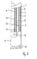
- Figur 3 zeigt schematisch einen Längsschnitt durch die Bohrvorrichtung.
- In Figur 1 ist ein Bohrwerkzeug und das zugehörige Gestänge während einer Bohrphase veranschaulicht. Das Bohr werkzeug besteht aus einem doppelwandigen Außenrohr 1 mit einer endseitigen Bohrkrone 2. Im Inneren des Außenrohres 1 ist koaxial ein separates, unabhängiges Kanalgestänge 3 mit einem Bohrkopf 4 angeordnet. Aus Gründen einer übersichtlichen Darstellung ist nicht gezeigt, daß sowohl das Außenrohr 1 als auch das Kanalgestänge 3 jeweils mit einem separaten Bohrantrieb versehen sind, die oberhalb des Erdreichs beispielsweise auf einer Lafette montiert sein können.
- Während der in der Figur 1 gezeigten Bohrphase wird das Außenrohr 1 und das Gestänge 3 gleichzeitig abgebohrt, wobei die Drehrichtungen gegenphasig sein können, wie die Drehrichtungspfeile 6 andeuten. Ebenso ist es möglich, aufgrund der beiden unabhängigen Bohrantriebe unterschiedliche Drehzahlen vorzusehen. Die Wahl der Drehrichtungen und der Drehzahlen wird in Abhängigkeit von den Eigenschaften des Erdreichs 5 im Hinblick auf einen optimalen Vortrieb gewählt. Durch einen Zuführkanal 7, der zwischen der Außenwand 8 und der Innenwand 9 des Außenrohres gebildet ist, wird ein Spülmedium, beispielsweise Bentonit-Suspension, als Bohrhilfe für das Außenrohr eingeleitet. Die dazu erforderlichen Pumpeinrichtungen und Vorratsbehälter sind an der Erdoberfläche installiert. Das Spülmedium gelangt im Bereich der Bohrkrone 2 über Austrittsöffnungen 10, die über den Umfang des Außenrohres 1 verteilt sind, in das von der Bohrkrone 2 beaufschlagte Erdreich. Das austretende Spülmedium ist in der Figur mit dem Bezugszeichen 11 versehen. Der Bohrgrund wird ferner mit Hilfe des Bohrkopfes 4 bearbeitet. Auch der Bohrkopf 4 ist mit Austrittsöffnungen (nicht dargestellt) für weiteres Spülmedium versehen, welches im Inneren des Kanalgestänges 3 zugeführt wird. Es entfaltet seine Wirkung im Bereich 13 vor dem Bohrkopf 4.
- In der Figur 1 ist eine Konfiguration dargestellt, bei welcher das Außenrohr 1 dem Kanalgestänge 3 vorauseilt. In Abhängigkeit von der jeweiligen Geologie kann es aber glei chermaßen zweckmäßig sein, das Kanalgestänge 3 vor dem Außenrohr 1 oder auf gleicher Höhe des Außenrohrs 1 zu führen.
- Im unteren Bereich weist das Gestänge 3 mindestens eine Injektionsdüse 12 auf, die im wesentlichen horizontal ausgerichtet ist. Sie ist im Inneren des Kanalgestänges 3 über eine Zuleitung (nicht dargestellt) mit einer Hochdruckpumpe an der Erdoberfläche verbunden, über welche eine Hochdruck-Suspension eingeleitet wird, wie die nachfolgende Beschreibung erläutert.
- Nach Erreichen der Endteufe wird das Gestänge 3 in eine Stellung gebracht, in welcher die Injektionsdüse 12 oder gegebenenfalls mehrere derartiger Injektionsdüsen vor der Bohrkrone 2 stehen. Diese Stellung veranschaulicht Figur 2. Anschließend wird die Hochdruck-Suspension 14 in das Erdreich 5 injiziert, wobei durch Drehen und Ziehen des Bohrgestänges 3 ein zylinderförmiger Injektionskörper 15 erzeugt wird.
- Gleichzeitig mit dem Kanalgestänge 3 wird auch das Außenrohr 1 zurückgezogen. Überschüssige Injektions-Suspension, die nicht mehr in das Erdreich 5 eindringen kann, tritt über eine Ringraum 16 zwischen dem Außenrohr 1 und dem KanaIgestänge 3 nach oben an die Erdoberfläche aus.
- In Figur 3 ist das Außenrohr 1 und das Kanalgestänge 3 teilweise im Längsschnitt entlang der Längsmittellinie 17 dargestellt. Es wird ersichtlich, daß das Kanalgestänge 3 aus zwei koaxialen Rohren besteht, wobei das äußere Kanalrohr mit dem Bezugszeichen 18, das innere Kanalrohr mit dem Bezugszeichen 20 versehen sind. Über das innere Kanalrohr 20 wird die Suspension an die Injektionsdüse 12 geleitet.
- Eine Spülleitung 21, die durch den Rohrraum zwischen dem äußeren Kanalrohr 18 und dem inneren Kanalrohr 20 gebildet wird, dient zur Versorgung mit dem weiteren Spülmedium, für das bevorzugt Wasser verwendet wird.
- Wie die Figur 3 veranschaulicht, kann dieses weitere Spülmedium auch zum Ausspülen des Ringraums 16 verwendet werden. Zu diesem Zweck ist das äußere Kanalrohr 18 mit mindestens einer Spüldüse 22 versehen, welche einen Flüssigkeitsstrahl von unten nach oben lenkt. Durch diese Maßnahme wird ein kontinuierlicher Rückfluß im Ringraum 16 sichergestellt, und ein Verstopfen oder teilweises Verengen des Ringraums 16 verhindert.
- Das austretende weitere Spülmedium fließt nach oben in Richtung auf die Erdoberfläche und unterstützt den Transport des Bohrguts, das von der Bohrkrone 2 und dem Bohrkopf 4 (Figur 1) unter dem zusätzlichen Einfluß von Spülmedium gelöst wurde. Es verhindert, daß sich dieses Bohrgut im Ringraum 16 zusammensetzt oder verklumpt.
- Grundsätzlich kann es ausreichend sein, daß eine einzige Spüldüse 22 vorhanden ist. Werden mehrere derartiger Spüldüsen entlang des Umfangs des äußeren Kanalrohrs 18 verteilt, so kann der kontinuierliche Bohrguttransport an die Erdoberfläche weiter verbessert werden. Insbesondere bei längeren Kanalgestängen 3 wird die Spülung des Ringraums 16 unterstützt, wenn Spüldüsen vertikal übereinander entlang des Kanalgestänges 3 angeordnet sind.
- Da eine Verstopfung oder Verengung des Ringraums 16 nicht nur beim Abbohren eintreten kann, wird die Spüldüse 22 gleichermaßen beim Rückziehen der Bohrvorrichtung, wie es im Zusammenhang mit Figur 2 beschrieben ist, betätigt. In dieser Phase wird überschüssige Hochdruck-Suspension nach oben abgeführt.
Claims (13)
dadurch gekennzeichnet, daß um das Kanalgestänge (3) ein separates Außenrohr (1) mit einer separaten Bohrkrone (2) und mit einem unabhängigen zweiten Bohrantrieb längsverschieblich angeordnet ist.
dadurch gekennzeichnet, daß das Außenrohr (1) doppelwandig zur Bildung eines Zuführkanals (7) für Spülmedium (11) ausgeführt ist, der im Bereich der Bohrkrone (2) mit Austrittsöffnungen (10) versehen ist.
dadurch gekennzeichnet, daß zwischen dem Außenrohr (1) und dem Kanalgestänge (3) ein Ringraum (16) vorhanden ist.
dadurch gekennzeichnet, daß das Kanalgestänge (3) eine Spülleitung für ein weiteres Spülmedium für den Bohrkopf (4) umfaßt.
dadurch gekennzeichnet, daß das Kanalgestänge (3) mindestens eine in den Ringraum (16) austretende und in Vortriebsrichtung hinter der Injektionsdüse (12) angeordnete Spüldüse (22) aufweist.
dadurch gekennzeichnet, daß die Spüldüse (22) vom bohrkopfseitigen Ende weggerichtet ist.
dadurch gekennzeichnet, daß mehrere Spüldüsen (22) über den Umfang des Kanalgestänges (3) verteilt sind.
dadurch gekennzeichnet, daß mehrere Spüldüsen (22) über die Länge des Kanalgestänges (3) verteilt sind.
gekennzeichnet durch folgende Verfahrensschritte:
dadurch gekennzeichnet, daß das Außenrohr (1) und das Kanalgestänge (3) mit unterschiedlicher Drehrichtung bewegt werden.
dadurch gekennzeichnet, daß das Außenrohr (1) und das Kanalgestänge (3) mit unterschiedlicher Drehzahl bewegt werden.
dadurch gekennzeichnet, daß das Außenrohr (1) und das Kanalgestänge (3) mit unterschiedlichem Vortrieb abgeteuft werden.
dadurch gekennzeichnet, daß während des Abteufens und/oder Zurückziehens über eine Spüldüse (22) weiteres Spülmedium in den Ringraum (16) zur Spülung des Ringraums (16) eingeleitet wird.
Priority Applications (1)
| Application Number | Priority Date | Filing Date | Title |
|---|---|---|---|
| AT88106156T ATE62293T1 (de) | 1987-06-02 | 1988-04-18 | Bohrvorrichtung fuer ein hochdruck-injektionsbohrverfahren. |
Applications Claiming Priority (2)
| Application Number | Priority Date | Filing Date | Title |
|---|---|---|---|
| DE3718480A DE3718480C2 (de) | 1987-06-02 | 1987-06-02 | Bohrvorrichtung für ein Hochdruck-Injektions-Bohrverfahren und Bohrverfahren unter Verwendung der Bohrvorrichtung |
| DE3718480 | 1987-06-02 |
Publications (2)
| Publication Number | Publication Date |
|---|---|
| EP0293584A1 true EP0293584A1 (de) | 1988-12-07 |
| EP0293584B1 EP0293584B1 (de) | 1991-04-03 |
Family
ID=6328901
Family Applications (1)
| Application Number | Title | Priority Date | Filing Date |
|---|---|---|---|
| EP88106156A Expired - Lifetime EP0293584B1 (de) | 1987-06-02 | 1988-04-18 | Bohrvorrichtung für ein Hochdruck-Injektions-Bohrverfahren |
Country Status (3)
| Country | Link |
|---|---|
| EP (1) | EP0293584B1 (de) |
| AT (1) | ATE62293T1 (de) |
| DE (2) | DE3718480C2 (de) |
Cited By (7)
| Publication number | Priority date | Publication date | Assignee | Title |
|---|---|---|---|---|
| FR2657906A1 (fr) * | 1990-02-06 | 1991-08-09 | Morillon Corvol Courbot | Procede de realisation de pieux moules dans le sol, pieux moules ainsi obtenus et tube-empreinte utilisable pour mettre en óoeuvre ledit procede. |
| FR2680380A1 (fr) * | 1991-08-14 | 1993-02-19 | Nit Co Ltd | Procede pour realiser un corps de fondation universel et dispositif pour mettre en óoeuvre ce procede. |
| EP0853162A3 (de) * | 1997-01-10 | 1999-02-03 | Juan Vicente Herrero Codina | Vorrichtung und Verfahren zur Herstellung von Gründungspfählen unter Verwendung eines Schneckenbohrers |
| EP1124037A1 (de) * | 2000-02-08 | 2001-08-16 | Günter Prof. Dr.-Ing. Klemm | Bohrvorrichtung |
| DE102011000320A1 (de) * | 2011-01-25 | 2012-07-26 | TERRA AG für Tiefbautechnik | Bohranlage zum Durchführen von Bohrungen im Erdreich |
| WO2017028645A1 (zh) * | 2015-08-18 | 2017-02-23 | 山东大学 | 防坍塌双向肋翼喷射注浆钻头、注浆固结系统及方法 |
| CN118360942A (zh) * | 2024-06-19 | 2024-07-19 | 四川坤德智联科技有限公司 | 一种多轴多层互剪高喷搅拌桩施工钻具及其使用方法 |
Families Citing this family (12)
| Publication number | Priority date | Publication date | Assignee | Title |
|---|---|---|---|---|
| DE3718631A1 (de) * | 1987-06-03 | 1988-12-22 | Gkn Keller Gmbh | Kombiniertes injektionsverfahren sowie vorrichtung zur herstellung eines hochverfestigten bodenvolumens bei gleichzeitiger stabilisierung des angrenzenden bodens |
| DE4121394A1 (de) * | 1991-06-28 | 1993-01-14 | Klemm Bohrtech | Verfahren und vorrichtung zum ausheben von erdmaterial oder bodenschaetzen |
| DE4138356A1 (de) * | 1991-11-21 | 1993-05-27 | Gu Tiefbau Ag | Bohrvorrichtung fuer den tiefbau sowie verfahren zum herstellen von stabilisierenden saeulen oder aehnlichen gebilden in erdreich |
| DE4323766A1 (de) * | 1993-07-15 | 1995-01-19 | Keller Grundbau Gmbh | Verfahren zum Ausbringen von Bindemittelsuspension |
| RU2211301C2 (ru) * | 2000-12-13 | 2003-08-27 | Ишкаев Раувель Калимуллинович | Способ обработки ствола скважины |
| RU2235190C2 (ru) * | 2001-08-29 | 2004-08-27 | Научно-производственное предприятие "Уфабурнефть" | Способ изоляции водопроявления при бурении скважин и устройство для его реализации |
| DE10319800A1 (de) * | 2003-04-30 | 2004-11-25 | Kleis, Simone | Hohlbohrkrone für Kernbohrmaschinen |
| DE102006023799B4 (de) * | 2006-05-20 | 2014-05-15 | Franki Grundbau Gmbh & Co.Kg | Vorrichtung zur Herstellung von Gründungselementen |
| DE102007023736B4 (de) * | 2007-05-22 | 2011-01-20 | Bauer Spezialtiefbau Gmbh | Schnellabbindende HDI |
| RU2386786C2 (ru) * | 2008-02-14 | 2010-04-20 | Открытое акционерное общество "Сургутнефтегаз" | Способ обработки высокопроницаемого пласта скважины |
| CN109441425B (zh) * | 2018-11-20 | 2022-02-11 | 常州大学 | 一种水平井双壁钻杆系统携岩能力测定方法 |
| CN113356255A (zh) * | 2021-06-25 | 2021-09-07 | 上海涵格建设工程有限公司 | 一种软弱地质建筑基础加固施工方法 |
Citations (7)
| Publication number | Priority date | Publication date | Assignee | Title |
|---|---|---|---|---|
| DE227376C (de) * | 1900-01-01 | |||
| GB318387A (en) * | 1928-08-31 | 1929-09-05 | August Wolfsholz | A process for sinking tubular bodies into the soil |
| US1853379A (en) * | 1926-12-29 | 1932-04-12 | Alexander G Rotinoff | Caisson and method of and means for sinking the same |
| US3604214A (en) * | 1968-08-16 | 1971-09-14 | Lee A Turzillo | Means and method of making columnar structures in situ |
| US3851490A (en) * | 1972-07-28 | 1974-12-03 | Kumagai Gumi Co Ltd | Construction pile having fluid injection means |
| GB2154630A (en) * | 1984-02-24 | 1985-09-11 | Matsuzawa Kiko Kabushiki Kaish | Construction method for foundation piling |
| FR2566813A1 (fr) * | 1984-06-29 | 1986-01-03 | Soletanche | Dispositif et procede pour la realisation de pieux en beton dans le sol et pieux obtenus par ce procede |
Family Cites Families (3)
| Publication number | Priority date | Publication date | Assignee | Title |
|---|---|---|---|---|
| US2494803A (en) * | 1946-08-22 | 1950-01-17 | Frost Jack | Multiple passage pipe sections for oil well drills or the like |
| US2684229A (en) * | 1951-09-06 | 1954-07-20 | Frank S Bergstrom | Apparatus for exploration drilling |
| DE2924393C2 (de) * | 1979-06-16 | 1983-06-23 | Brückner Grundbau GmbH, 4300 Essen | Bohrvorrichtung zum Überlagerungsbohren |
-
1987
- 1987-06-02 DE DE3718480A patent/DE3718480C2/de not_active Expired - Fee Related
-
1988
- 1988-04-18 EP EP88106156A patent/EP0293584B1/de not_active Expired - Lifetime
- 1988-04-18 AT AT88106156T patent/ATE62293T1/de not_active IP Right Cessation
- 1988-04-18 DE DE8888106156T patent/DE3862239D1/de not_active Expired - Fee Related
Patent Citations (7)
| Publication number | Priority date | Publication date | Assignee | Title |
|---|---|---|---|---|
| DE227376C (de) * | 1900-01-01 | |||
| US1853379A (en) * | 1926-12-29 | 1932-04-12 | Alexander G Rotinoff | Caisson and method of and means for sinking the same |
| GB318387A (en) * | 1928-08-31 | 1929-09-05 | August Wolfsholz | A process for sinking tubular bodies into the soil |
| US3604214A (en) * | 1968-08-16 | 1971-09-14 | Lee A Turzillo | Means and method of making columnar structures in situ |
| US3851490A (en) * | 1972-07-28 | 1974-12-03 | Kumagai Gumi Co Ltd | Construction pile having fluid injection means |
| GB2154630A (en) * | 1984-02-24 | 1985-09-11 | Matsuzawa Kiko Kabushiki Kaish | Construction method for foundation piling |
| FR2566813A1 (fr) * | 1984-06-29 | 1986-01-03 | Soletanche | Dispositif et procede pour la realisation de pieux en beton dans le sol et pieux obtenus par ce procede |
Non-Patent Citations (1)
| Title |
|---|
| PATENT ABSTRACTS OF JAPAN, Band 7, Nr. 20 (M-188)[1165], 26. Januar 1983; & JP-A-57 174 528 (KUBOTA TEKKO K.K.) 27-10-1982 * |
Cited By (11)
| Publication number | Priority date | Publication date | Assignee | Title |
|---|---|---|---|---|
| FR2657906A1 (fr) * | 1990-02-06 | 1991-08-09 | Morillon Corvol Courbot | Procede de realisation de pieux moules dans le sol, pieux moules ainsi obtenus et tube-empreinte utilisable pour mettre en óoeuvre ledit procede. |
| EP0441077A1 (de) * | 1990-02-06 | 1991-08-14 | Entreprises Morillon Corvol Courbot S.A. | Herstellungsverfahren von Ortbetonfählen und Eindruckrohr zur Durchführung des Verfahrens |
| FR2680380A1 (fr) * | 1991-08-14 | 1993-02-19 | Nit Co Ltd | Procede pour realiser un corps de fondation universel et dispositif pour mettre en óoeuvre ce procede. |
| ES2065204A2 (es) * | 1991-08-14 | 1995-02-01 | Nit Co Ltd | Metodo para formacion omnidireccional de una masa de terreno mejorada y el correspondiente equipo. |
| EP0853162A3 (de) * | 1997-01-10 | 1999-02-03 | Juan Vicente Herrero Codina | Vorrichtung und Verfahren zur Herstellung von Gründungspfählen unter Verwendung eines Schneckenbohrers |
| US6079906A (en) * | 1997-01-10 | 2000-06-27 | Herrero Codina; Juan Vicente | Method for making foundation piling with drilling machines |
| EP1124037A1 (de) * | 2000-02-08 | 2001-08-16 | Günter Prof. Dr.-Ing. Klemm | Bohrvorrichtung |
| DE102011000320A1 (de) * | 2011-01-25 | 2012-07-26 | TERRA AG für Tiefbautechnik | Bohranlage zum Durchführen von Bohrungen im Erdreich |
| WO2017028645A1 (zh) * | 2015-08-18 | 2017-02-23 | 山东大学 | 防坍塌双向肋翼喷射注浆钻头、注浆固结系统及方法 |
| US11085244B2 (en) | 2015-08-18 | 2021-08-10 | Shandong University | Anti-collapse jet grouting drill bit with bi-directional rib wings, grouting consolidation system and method |
| CN118360942A (zh) * | 2024-06-19 | 2024-07-19 | 四川坤德智联科技有限公司 | 一种多轴多层互剪高喷搅拌桩施工钻具及其使用方法 |
Also Published As
| Publication number | Publication date |
|---|---|
| DE3718480C2 (de) | 1994-04-14 |
| EP0293584B1 (de) | 1991-04-03 |
| ATE62293T1 (de) | 1991-04-15 |
| DE3718480C1 (de) | 1988-09-22 |
| DE3862239D1 (de) | 1991-05-08 |
Similar Documents
| Publication | Publication Date | Title |
|---|---|---|
| DE3718480C1 (de) | Bohrvorrichtung fuer ein Hochdruck-Injektions-Bohrverfahren | |
| DE2630027C2 (de) | Verfahren zum Herstellen von dichten Schutzwänden im Erdreich sowie Vorrichtung zum Durchführen des Verfahrens | |
| DE2540590A1 (de) | Verfahren und vorrichtung zur durchfuehrung einer bohrung unterhalb eines hindernisses laengs einer bogenfoermigen bahn | |
| EP0548588B1 (de) | Vorrichtung zur Herstellung von Erdbohrungen | |
| DE2737330C2 (de) | Verfahren zum Auffahren und Ausbauen eines Tunnels und Bohreinrichtung zur Durchführung des Verfahrens | |
| EP0474070B1 (de) | Verfahren und Vorrichtung zum Herstellen einer Schmal- oder Schlitzwand in Erdreich | |
| EP0522446B1 (de) | Verfahren zur Richtungssteuerung eines Erdbohrgerätes sowie Vorrichtung zur Herstellung von Erdbohrungen | |
| DE3726472C2 (de) | ||
| EP0819819B1 (de) | Fräskopf, Bohrvorrichtung sowie Vorrichtung und Verfahren zum Meeresbodenbohren | |
| AT413422B (de) | Verfahren und vorrichtung zum vermessen eines bohrlochs | |
| EP0634528B1 (de) | Verfahren zum Ausbringen von Bindemittelsuspension | |
| EP0509385A1 (de) | Verfahren zum Herstellen von Beton- und Zementkörpern im Boden | |
| DE19738171A1 (de) | Bohrgerät | |
| EP0837190A2 (de) | Vorrichtung und Verfahren zur kontrollierten Herstellung von Pfählen und Pfahlwänden im Boden | |
| AT393292B (de) | Vorrichtung zur herstellung von durch zugabe von binde- oder abdichtemitteln verdichteten bodenabschnitten | |
| DE3729561C2 (de) | ||
| DE3728270A1 (de) | Verfahren und vorrichtung zur herstellung von betonpfaehlen im boden | |
| DE10327470B3 (de) | Vorrichtung zur Herstellung von Einzelschlitzen oder durchgehenden Wänden im Erdreich nach dem Mixed-in-Place-Verfahren | |
| DE19533014A1 (de) | Verfahren zur Herstellung von Rohrwänden oder gemischten Spundwänden mit Rohrtragbohlen | |
| DE4121394C2 (de) | ||
| EP2666911B1 (de) | Verfahren zum Herstellen einer Bodenmörtelwand im Boden | |
| DE3737259C1 (en) | Apparatus and method for high-pressure injection | |
| DE10319800A1 (de) | Hohlbohrkrone für Kernbohrmaschinen | |
| DE3513194C1 (de) | Vorrichtung zum Durchdringen oberflächennaher Bodenschichten | |
| EP3708764B1 (de) | Bohrvorrichtung |
Legal Events
| Date | Code | Title | Description |
|---|---|---|---|
| ITCL | It: translation for ep claims filed |
Representative=s name: BARZANO' E ZANARDO ROMA S.P.A. |
|
| PUAI | Public reference made under article 153(3) epc to a published international application that has entered the european phase |
Free format text: ORIGINAL CODE: 0009012 |
|
| AK | Designated contracting states |
Kind code of ref document: A1 Designated state(s): AT CH DE ES FR GB LI |
|
| 17P | Request for examination filed |
Effective date: 19890607 |
|
| 17Q | First examination report despatched |
Effective date: 19900426 |
|
| GRAA | (expected) grant |
Free format text: ORIGINAL CODE: 0009210 |
|
| AK | Designated contracting states |
Kind code of ref document: B1 Designated state(s): AT CH DE ES FR GB LI |
|
| PG25 | Lapsed in a contracting state [announced via postgrant information from national office to epo] |
Ref country code: GB Effective date: 19910403 Ref country code: FR Effective date: 19910403 Ref country code: ES Free format text: THE PATENT HAS BEEN ANNULLED BY A DECISION OF A NATIONAL AUTHORITY Effective date: 19910403 |
|
| REF | Corresponds to: |
Ref document number: 62293 Country of ref document: AT Date of ref document: 19910415 Kind code of ref document: T |
|
| REF | Corresponds to: |
Ref document number: 3862239 Country of ref document: DE Date of ref document: 19910508 |
|
| EN | Fr: translation not filed | ||
| GBV | Gb: ep patent (uk) treated as always having been void in accordance with gb section 77(7)/1977 [no translation filed] | ||
| PLBE | No opposition filed within time limit |
Free format text: ORIGINAL CODE: 0009261 |
|
| STAA | Information on the status of an ep patent application or granted ep patent |
Free format text: STATUS: NO OPPOSITION FILED WITHIN TIME LIMIT |
|
| 26N | No opposition filed | ||
| PGFP | Annual fee paid to national office [announced via postgrant information from national office to epo] |
Ref country code: CH Payment date: 19920513 Year of fee payment: 5 |
|
| PGFP | Annual fee paid to national office [announced via postgrant information from national office to epo] |
Ref country code: AT Payment date: 19930421 Year of fee payment: 6 |
|
| PG25 | Lapsed in a contracting state [announced via postgrant information from national office to epo] |
Ref country code: LI Effective date: 19930430 Ref country code: CH Effective date: 19930430 |
|
| PGFP | Annual fee paid to national office [announced via postgrant information from national office to epo] |
Ref country code: DE Payment date: 19930430 Year of fee payment: 6 |
|
| REG | Reference to a national code |
Ref country code: CH Ref legal event code: PL |
|
| PG25 | Lapsed in a contracting state [announced via postgrant information from national office to epo] |
Ref country code: AT Effective date: 19940418 |
|
| PG25 | Lapsed in a contracting state [announced via postgrant information from national office to epo] |
Ref country code: DE Effective date: 19950103 |