EP0293178A2 - Verfahren und Gerät zum Schneiden von Betonplatten mit hohlräumigem Kern - Google Patents
Verfahren und Gerät zum Schneiden von Betonplatten mit hohlräumigem Kern Download PDFInfo
- Publication number
- EP0293178A2 EP0293178A2 EP88304724A EP88304724A EP0293178A2 EP 0293178 A2 EP0293178 A2 EP 0293178A2 EP 88304724 A EP88304724 A EP 88304724A EP 88304724 A EP88304724 A EP 88304724A EP 0293178 A2 EP0293178 A2 EP 0293178A2
- Authority
- EP
- European Patent Office
- Prior art keywords
- cutting
- slab
- blades
- mix
- cutting blades
- Prior art date
- Legal status (The legal status is an assumption and is not a legal conclusion. Google has not performed a legal analysis and makes no representation as to the accuracy of the status listed.)
- Granted
Links
Images

Classifications
-
- B—PERFORMING OPERATIONS; TRANSPORTING
- B28—WORKING CEMENT, CLAY, OR STONE
- B28B—SHAPING CLAY OR OTHER CERAMIC COMPOSITIONS; SHAPING SLAG; SHAPING MIXTURES CONTAINING CEMENTITIOUS MATERIAL, e.g. PLASTER
- B28B11/00—Apparatus or processes for treating or working the shaped or preshaped articles
- B28B11/003—Apparatus or processes for treating or working the shaped or preshaped articles the shaping of preshaped articles, e.g. by bending
- B28B11/006—Making hollow articles or partly closed articles
-
- B—PERFORMING OPERATIONS; TRANSPORTING
- B28—WORKING CEMENT, CLAY, OR STONE
- B28B—SHAPING CLAY OR OTHER CERAMIC COMPOSITIONS; SHAPING SLAG; SHAPING MIXTURES CONTAINING CEMENTITIOUS MATERIAL, e.g. PLASTER
- B28B11/00—Apparatus or processes for treating or working the shaped or preshaped articles
- B28B11/14—Apparatus or processes for treating or working the shaped or preshaped articles for dividing shaped articles by cutting
- B28B11/16—Apparatus or processes for treating or working the shaped or preshaped articles for dividing shaped articles by cutting for extrusion or for materials supplied in long webs
- B28B11/163—Apparatus or processes for treating or working the shaped or preshaped articles for dividing shaped articles by cutting for extrusion or for materials supplied in long webs in which the cutting device is moved longitudinally with the moving strand
- B28B11/165—Apparatus or processes for treating or working the shaped or preshaped articles for dividing shaped articles by cutting for extrusion or for materials supplied in long webs in which the cutting device is moved longitudinally with the moving strand mounted on a carrier
-
- Y—GENERAL TAGGING OF NEW TECHNOLOGICAL DEVELOPMENTS; GENERAL TAGGING OF CROSS-SECTIONAL TECHNOLOGIES SPANNING OVER SEVERAL SECTIONS OF THE IPC; TECHNICAL SUBJECTS COVERED BY FORMER USPC CROSS-REFERENCE ART COLLECTIONS [XRACs] AND DIGESTS
- Y10—TECHNICAL SUBJECTS COVERED BY FORMER USPC
- Y10T—TECHNICAL SUBJECTS COVERED BY FORMER US CLASSIFICATION
- Y10T83/00—Cutting
- Y10T83/02—Other than completely through work thickness
- Y10T83/0207—Other than completely through work thickness or through work presented
-
- Y—GENERAL TAGGING OF NEW TECHNOLOGICAL DEVELOPMENTS; GENERAL TAGGING OF CROSS-SECTIONAL TECHNOLOGIES SPANNING OVER SEVERAL SECTIONS OF THE IPC; TECHNICAL SUBJECTS COVERED BY FORMER USPC CROSS-REFERENCE ART COLLECTIONS [XRACs] AND DIGESTS
- Y10—TECHNICAL SUBJECTS COVERED BY FORMER USPC
- Y10T—TECHNICAL SUBJECTS COVERED BY FORMER US CLASSIFICATION
- Y10T83/00—Cutting
- Y10T83/02—Other than completely through work thickness
- Y10T83/0304—Grooving
-
- Y—GENERAL TAGGING OF NEW TECHNOLOGICAL DEVELOPMENTS; GENERAL TAGGING OF CROSS-SECTIONAL TECHNOLOGIES SPANNING OVER SEVERAL SECTIONS OF THE IPC; TECHNICAL SUBJECTS COVERED BY FORMER USPC CROSS-REFERENCE ART COLLECTIONS [XRACs] AND DIGESTS
- Y10—TECHNICAL SUBJECTS COVERED BY FORMER USPC
- Y10T—TECHNICAL SUBJECTS COVERED BY FORMER US CLASSIFICATION
- Y10T83/00—Cutting
- Y10T83/929—Tool or tool with support
- Y10T83/9411—Cutting couple type
Definitions
- the present invention relates to a method in accordance with the preamble of claim 1 for cutting hollow-cored concrete slabs.
- the invention also concerns an apparatus for implementing the method.
- the slabs are conventionally cast on long beds using a continuous slip-forming extrusion method.
- the cored slabs are prestressed structures cast from relatively stiff mixes.
- openings and recesses are worked into the slabs according to the individual specifications of construction drawings. Working is performed using manual methods by first measuring the elements with a tape measure and marking the cutting points of elements. Referencing to the cutting point, the position of each opening is measured and marked, after which manual tools are used to scrape the openings free of unhardened mix that is then placed in a waste mix container. In some cases, the ends of slabs are trimmed immediately after the casting operation prior to the hardening of the mix. The immediate cutting is most typically performed using manual tools, e.g., a circular saw.
- the immediate cutting is made over such a wide length (10...20 cm) that the ends of hollow cores are visible from the cutting point, allowing the ends to be filled with concrete mortar or mix using manual methods.
- the entire set of cored slabs is covered with a protective blanket until the final setting of the concrete.
- the slabs are cut by using a circular saw with a diamond-tipped blade, which is capable of cutting the set concrete, in addition to the tendons.
- the elements can be transferred from the casting bed to be bundled and then put into final storage until they are later transported to the construction site.
- the ends of the hollow cores are always stoppered by a suitable type of plug so that the jointing mix applied at the construction site to the joint between the element ends is not able to flow into and fill up the cores.
- the stopper plugs of the hollow cores in the cored element perform as casting plugs, but they may also be applicable as supports for the wall constructions resting on the ends of cored slab.
- the type of plug conventionally used is a cast concrete plug or a detachable, cut-shaped, molded plastic plug.
- the present invention aims to overcome the disadvantages found in prior-art techniques and to provide an entirely novel method and apparatus for cutting prestressed hollow-cored concrete slab.
- the method is based on cutting the hollow-cored slabs immediately after the casting phase while simultaneously filling the ends of the hollow cores using the excess mix from the cutting phase as a filler.
- the invention provides remarkable advantages.
- the labour-intensive sawing phase is shortened and the manual labour-requiring operation of filling the core ends is replaced by the filling of the core ends already in conjunction with the instant cutting phase.
- Figure 1 is a partially cross-sectioned side view of a cutting apparatus in accordance with the invention.
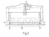
- Figure 2 is a partially cross-sectioned front view of the cutting apparatus shown in Fig. 1.
- the invention is based on arranging an instant-action cutting/-plugging apparatus 9 to be movable closely coupled to the slipforming extruder.
- the apparatus is movable on wheels 7 on side rails 8 of the casting bed.
- Drive means for the apparatus is provided by a separate transfer motor 12.
- the apparatus has preferably a distance measuring device 13, with help of which the apparatus is shifted forward on the casting line over the length of the slab element so as to locate an end cutting knife 1, which extends crosswise over the entire element width, at the separation point of the elements.
- cutting blades 3 mutually aligned in a V-shaped posture, are driven by means of an auxiliary mechanism 15 downward into the fresh unhardened mix, obliquely approaching each other in the mix.
- a tip 10 of the cutting blade 3 is preferably saw-shaped to advantageously help the blade 3 penetrate into the mix without distorting its cast shape.
- the cutting blade 3 can be subjected to a sideways reciprocating motion by means of, e.g., a reciprocating actuator 6 implemented using a separate rotational drive and an eccentric cam disc. Sideways expansion of the mix is prevented by a mold wall 11 resting against the side of the fresh cast slab.
- the frequency of the reciprocating crosswise motion is 5 to 600 strokes/min, preferably approx. 300 strokes/min.
- the height of the cutting blade 3 is adjustable by means of a separate mechanical adjustment 4, which allows the adaptation of the apparatus into the fabrication of cored slabs of different heights.
- a wedge-shaped end cutting knife 1 which extends over the entire width of the cored slab, is started.
- the end cutting knife 1 is pushed with help of a mechanical actuator 2 down into the fresh, unhardened mix close to the cutting blades 3.
- a crosswise reciprocating actuator 6 and a saw-shaped tip similar to those of the cutting blades, can be used.
- Sides 16 of the end cutting knife facing the concrete mix are substantially parallel to the cutting blades 3.
- the concrete mix of the cast slab can be moistened with help of a separate water spraying nozzle 14 in order to plasticize the extremely stiff mix.
- the downward penetration of the end cutting knife 1 through the unhardened mix to its lower position simultaneously creates an instant cutting gap between the opposing ends of elements.
- the combination of the reciprocating motion, downward gravitational motion, and wedge-shaped form of the end cutting knife 1 works the mix between the cutting blade 3 and the knife 1 so that the mix is plasticized and transferred from the ridges as well as from the upper and lower surfaces of the slab into the open cores thus forming a homogeneous concrete mix sheet 17 from the original open core structure.
- the cutting blades 3 are lifted by means of a mechanical actuator 15 to an upper position. Because of the extremely thin construction of the cutting blades 3 and the sustained downward pushing action of the end cutting knife 1, the homogeneous concrete sheet 17 formed at the cutting point is not severed but instead remains in place during all cutting phases. When the cutting blades 3 are at their upper positions, the end cutting knife 1 yet further finalizes the seam formed between an end 18 of the slab and the homogeneous concrete sheet 17, which forms a plug at the end of slab, by compacting the voids formed at the ends by the withdrawal of the cutting blade 3.
- the pushing action and a small crosswise shearing motion of the end cutting knife 1 compacts the concrete sheet 17 to adhere to the end 18 of slab thus plugging the cores of the slab.
- the end cutting knife 1 is lifted up by means of the mechanical actuator 2 to allow the transfer of the cutting apparatus to the next cutting point.
- the apparatus measures the lengths of elements, performs an immediate cutting of the hollow-cored slab, and works appropriate plugging material from the excess mix remaining from the cutting operation, and plugs the cores of the hollow-cored slab in a single work phase.
Landscapes
- Engineering & Computer Science (AREA)
- Structural Engineering (AREA)
- Chemical & Material Sciences (AREA)
- Ceramic Engineering (AREA)
- Mechanical Engineering (AREA)
- Devices For Post-Treatments, Processing, Supply, Discharge, And Other Processes (AREA)
- Processing Of Stones Or Stones Resemblance Materials (AREA)
Priority Applications (1)
| Application Number | Priority Date | Filing Date | Title |
|---|---|---|---|
| AT88304724T ATE63352T1 (de) | 1987-05-28 | 1988-05-25 | Verfahren und geraet zum schneiden von betonplatten mit hohlraeumigem kern. |
Applications Claiming Priority (2)
| Application Number | Priority Date | Filing Date | Title |
|---|---|---|---|
| FI872372A FI78018C (fi) | 1987-05-28 | 1987-05-28 | Foerfarande och anordning foer kapning av haolelement. |
| FI872372 | 1987-05-28 |
Publications (3)
| Publication Number | Publication Date |
|---|---|
| EP0293178A2 true EP0293178A2 (de) | 1988-11-30 |
| EP0293178A3 EP0293178A3 (en) | 1989-08-23 |
| EP0293178B1 EP0293178B1 (de) | 1991-05-08 |
Family
ID=8524561
Family Applications (1)
| Application Number | Title | Priority Date | Filing Date |
|---|---|---|---|
| EP88304724A Expired - Lifetime EP0293178B1 (de) | 1987-05-28 | 1988-05-25 | Verfahren und Gerät zum Schneiden von Betonplatten mit hohlräumigem Kern |
Country Status (8)
| Country | Link |
|---|---|
| US (1) | US4923379A (de) |
| EP (1) | EP0293178B1 (de) |
| AT (1) | ATE63352T1 (de) |
| DE (1) | DE3862681D1 (de) |
| DK (1) | DK290788A (de) |
| ES (1) | ES2022620B3 (de) |
| FI (1) | FI78018C (de) |
| NO (1) | NO163681C (de) |
Cited By (2)
| Publication number | Priority date | Publication date | Assignee | Title |
|---|---|---|---|---|
| GB2281050A (en) * | 1993-08-05 | 1995-02-22 | Hollow Core Systems | Method of cutting hollow core slabs |
| CN105954643A (zh) * | 2016-06-17 | 2016-09-21 | 资阳中车电力机车有限公司 | 一种便携式多芯接插件校线仪 |
Families Citing this family (8)
| Publication number | Priority date | Publication date | Assignee | Title |
|---|---|---|---|---|
| US6148560A (en) * | 1998-05-01 | 2000-11-21 | Vinifera, Inc. | Grafting machine |
| US6209855B1 (en) * | 1999-05-10 | 2001-04-03 | Canzone Limited | Gas/liquid mixing apparatus and method |
| US20060038314A1 (en) * | 2001-11-27 | 2006-02-23 | Capaldo Kevin P | Method for producing low birefringence plastic film |
| US7757451B2 (en) * | 2008-11-18 | 2010-07-20 | Lee Lum Mark E | Ventilated building block |
| CN103009467B (zh) * | 2012-12-24 | 2015-01-28 | 安徽同步自动化科技有限公司 | 一种耐火砖坯抛射成型方法及成型系统 |
| US10477883B2 (en) | 2015-08-25 | 2019-11-19 | Cornelius, Inc. | Gas injection assemblies for batch beverages having spargers |
| US10785996B2 (en) | 2015-08-25 | 2020-09-29 | Cornelius, Inc. | Apparatuses, systems, and methods for inline injection of gases into liquids |
| US11040314B2 (en) | 2019-01-08 | 2021-06-22 | Marmon Foodservice Technologies, Inc. | Apparatuses, systems, and methods for injecting gasses into beverages |
Family Cites Families (8)
| Publication number | Priority date | Publication date | Assignee | Title |
|---|---|---|---|---|
| DE275382C (de) * | ||||
| CA763876A (en) * | 1962-07-06 | 1967-07-25 | Span-Deck | Apparatus and method for forming concrete planks or slabs |
| DE2112916C3 (de) * | 1971-03-17 | 1974-01-31 | Hans Van 5130 Geilenkirchen Daal | Verfahren und Vorrichtung zur maschinellen Herstellung von Ziegelsteinen mit mindestens einer handformsteingleichen Oberfläche |
| CH570862A5 (de) * | 1972-12-08 | 1975-12-31 | Klopfer Albert | |
| EP0093785B1 (de) * | 1982-05-03 | 1985-11-13 | Societe Des Produits Nestle S.A. | Verfahren zum Formen von Gebäck |
| US4608902A (en) * | 1984-10-24 | 1986-09-02 | Charles E. Long | Measuring and cutting tool guiding device for use in the formation of fiber glass ducts |
| GB8516674D0 (en) * | 1985-07-02 | 1985-08-07 | Unilever Plc | Cutting elongated strand of soft confection material |
| US4798118A (en) * | 1988-02-26 | 1989-01-17 | Carithers Jr Charles H | Apparatus for cutting V-grooves in mats |
-
1987
- 1987-05-28 FI FI872372A patent/FI78018C/fi not_active IP Right Cessation
-
1988
- 1988-05-19 NO NO882183A patent/NO163681C/no unknown
- 1988-05-25 EP EP88304724A patent/EP0293178B1/de not_active Expired - Lifetime
- 1988-05-25 ES ES88304724T patent/ES2022620B3/es not_active Expired - Lifetime
- 1988-05-25 AT AT88304724T patent/ATE63352T1/de not_active IP Right Cessation
- 1988-05-25 DE DE8888304724T patent/DE3862681D1/de not_active Expired - Fee Related
- 1988-05-26 US US07/200,442 patent/US4923379A/en not_active Expired - Fee Related
- 1988-05-27 DK DK290788A patent/DK290788A/da not_active Application Discontinuation
Cited By (4)
| Publication number | Priority date | Publication date | Assignee | Title |
|---|---|---|---|---|
| GB2281050A (en) * | 1993-08-05 | 1995-02-22 | Hollow Core Systems | Method of cutting hollow core slabs |
| US5529735A (en) * | 1993-08-05 | 1996-06-25 | Hollow Core Systems (Mid-East) Limited | Cutting of hollow core slabs |
| GB2281050B (en) * | 1993-08-05 | 1997-03-26 | Hollow Core Systems | Cutting of hollow core slabs |
| CN105954643A (zh) * | 2016-06-17 | 2016-09-21 | 资阳中车电力机车有限公司 | 一种便携式多芯接插件校线仪 |
Also Published As
| Publication number | Publication date |
|---|---|
| DE3862681D1 (de) | 1991-06-13 |
| NO882183L (no) | 1988-11-29 |
| FI78018B (fi) | 1989-02-28 |
| ATE63352T1 (de) | 1991-05-15 |
| FI872372A0 (fi) | 1987-05-28 |
| ES2022620B3 (es) | 1991-12-01 |
| DK290788A (da) | 1988-11-29 |
| NO882183D0 (no) | 1988-05-19 |
| DK290788D0 (da) | 1988-05-27 |
| FI872372A7 (fi) | 1988-11-29 |
| EP0293178B1 (de) | 1991-05-08 |
| NO163681C (no) | 1990-07-04 |
| EP0293178A3 (en) | 1989-08-23 |
| NO163681B (no) | 1990-03-26 |
| FI78018C (fi) | 1989-06-12 |
| US4923379A (en) | 1990-05-08 |
Similar Documents
| Publication | Publication Date | Title |
|---|---|---|
| EP0293178B1 (de) | Verfahren und Gerät zum Schneiden von Betonplatten mit hohlräumigem Kern | |
| CN103817778B (zh) | 预制清水混凝土构件施工方法 | |
| SK161594A3 (en) | Device for elimination of upper waste layer, originated at cutting of plastic air-entrained concrete blocks or similar products | |
| HUP0301554A2 (en) | Method and device for correcting the position of a slab construction consisting of precast concrete slabs | |
| CN111002430B (zh) | 一种混凝土夯实设备 | |
| GB2174639A (en) | Extrusion machine for producing hollow concrete slabs | |
| EP2255938B1 (de) | Vorrichtung und Verfahren zum Anbringen einer Schalung auf einer Schalungsauflage für Betonfertigbauteile | |
| BG100080A (bg) | Машина и метод за производство на цигли за покриви | |
| US4102618A (en) | Manufacturing benches for moulded construction | |
| GB2197005A (en) | Building element and method of manufacture | |
| CN211547217U (zh) | 一种道路施工用辅助装置 | |
| US5269625A (en) | Rock depress float | |
| CN219711000U (zh) | 一种塑形阶段混凝土伸缩缝预制机 | |
| US3057274A (en) | Method of forming road joints and machine for use therein | |
| EP0309328B1 (de) | Vorrichtung zur Herstellung von Betonbalken | |
| EP0517505A1 (de) | Verfahren und Vorrichtung zum Auflegen eines Oberflächenschichtstoffes auf eine Betonfertigplatte | |
| CN117211527A (zh) | 一种防止叠合板板带位置漏浆的模板及其施工方法 | |
| CN110405937B (zh) | 一种长线台座法生产预制混凝土叠合板底板的分段方法 | |
| DE102022105755A1 (de) | Vorrichtung und Verfahren zur baustellenseitigen Oberflächenbearbeitung von plastischen Massen | |
| US1206553A (en) | Method for molding tiles. | |
| CN116922584B (zh) | 一种滑模摊铺机齿墙模具切缝装置 | |
| JPH05329795A (ja) | 未硬化板材の切断装置 | |
| CN119260925B (zh) | 预加应力的预制钢筋混凝土道路板及其制备方法 | |
| US20200298445A1 (en) | Method for manufacturing a curable, slab-like light-conducting body, mold for carrying out the method and a light-conducting body produced in accordance with the method | |
| CN214329773U (zh) | 大面积饰面砖粘贴砂浆摊铺装置 |
Legal Events
| Date | Code | Title | Description |
|---|---|---|---|
| PUAI | Public reference made under article 153(3) epc to a published international application that has entered the european phase |
Free format text: ORIGINAL CODE: 0009012 |
|
| AK | Designated contracting states |
Kind code of ref document: A2 Designated state(s): AT BE CH DE ES FR GB GR IT LI NL SE |
|
| 17P | Request for examination filed |
Effective date: 19890227 |
|
| PUAL | Search report despatched |
Free format text: ORIGINAL CODE: 0009013 |
|
| AK | Designated contracting states |
Kind code of ref document: A3 Designated state(s): AT BE CH DE ES FR GB GR IT LI NL SE |
|
| RHK1 | Main classification (correction) |
Ipc: E04C 2/04 |
|
| 17Q | First examination report despatched |
Effective date: 19900719 |
|
| GRAA | (expected) grant |
Free format text: ORIGINAL CODE: 0009210 |
|
| RAP1 | Party data changed (applicant data changed or rights of an application transferred) |
Owner name: LOHJA PARMA ENGINEERING LPE OY |
|
| AK | Designated contracting states |
Kind code of ref document: B1 Designated state(s): AT BE CH DE ES FR GB GR IT LI NL SE |
|
| PG25 | Lapsed in a contracting state [announced via postgrant information from national office to epo] |
Ref country code: LI Effective date: 19910508 Ref country code: GR Free format text: LAPSE BECAUSE OF FAILURE TO SUBMIT A TRANSLATION OF THE DESCRIPTION OR TO PAY THE FEE WITHIN THE PRESCRIBED TIME-LIMIT Effective date: 19910508 Ref country code: CH Effective date: 19910508 |
|
| REF | Corresponds to: |
Ref document number: 63352 Country of ref document: AT Date of ref document: 19910515 Kind code of ref document: T |
|
| REF | Corresponds to: |
Ref document number: 3862681 Country of ref document: DE Date of ref document: 19910613 |
|
| PGFP | Annual fee paid to national office [announced via postgrant information from national office to epo] |
Ref country code: ES Payment date: 19910624 Year of fee payment: 4 |
|
| PGFP | Annual fee paid to national office [announced via postgrant information from national office to epo] |
Ref country code: AT Payment date: 19910725 Year of fee payment: 4 |
|
| ET | Fr: translation filed | ||
| ITF | It: translation for a ep patent filed | ||
| REG | Reference to a national code |
Ref country code: CH Ref legal event code: PL |
|
| PGFP | Annual fee paid to national office [announced via postgrant information from national office to epo] |
Ref country code: FR Payment date: 19920224 Year of fee payment: 5 |
|
| PLBE | No opposition filed within time limit |
Free format text: ORIGINAL CODE: 0009261 |
|
| STAA | Information on the status of an ep patent application or granted ep patent |
Free format text: STATUS: NO OPPOSITION FILED WITHIN TIME LIMIT |
|
| PGFP | Annual fee paid to national office [announced via postgrant information from national office to epo] |
Ref country code: SE Payment date: 19920406 Year of fee payment: 5 |
|
| PGFP | Annual fee paid to national office [announced via postgrant information from national office to epo] |
Ref country code: BE Payment date: 19920422 Year of fee payment: 5 |
|
| 26N | No opposition filed | ||
| PG25 | Lapsed in a contracting state [announced via postgrant information from national office to epo] |
Ref country code: GB Effective date: 19920525 Ref country code: AT Effective date: 19920525 |
|
| PG25 | Lapsed in a contracting state [announced via postgrant information from national office to epo] |
Ref country code: ES Free format text: LAPSE BECAUSE OF NON-PAYMENT OF DUE FEES Effective date: 19920526 |
|
| PGFP | Annual fee paid to national office [announced via postgrant information from national office to epo] |
Ref country code: NL Payment date: 19920531 Year of fee payment: 5 |
|
| PGFP | Annual fee paid to national office [announced via postgrant information from national office to epo] |
Ref country code: DE Payment date: 19920611 Year of fee payment: 5 |
|
| GBPC | Gb: european patent ceased through non-payment of renewal fee |
Effective date: 19920525 |
|
| PG25 | Lapsed in a contracting state [announced via postgrant information from national office to epo] |
Ref country code: SE Effective date: 19930526 |
|
| PG25 | Lapsed in a contracting state [announced via postgrant information from national office to epo] |
Ref country code: BE Effective date: 19930531 |
|
| BERE | Be: lapsed |
Owner name: LOHJA PARMA ENGINEERING LPE OY Effective date: 19930531 |
|
| PG25 | Lapsed in a contracting state [announced via postgrant information from national office to epo] |
Ref country code: NL Effective date: 19931201 |
|
| NLV4 | Nl: lapsed or anulled due to non-payment of the annual fee | ||
| PG25 | Lapsed in a contracting state [announced via postgrant information from national office to epo] |
Ref country code: FR Effective date: 19940131 |
|
| REG | Reference to a national code |
Ref country code: FR Ref legal event code: ST |
|
| EUG | Se: european patent has lapsed |
Ref document number: 88304724.3 Effective date: 19931210 |
|
| PG25 | Lapsed in a contracting state [announced via postgrant information from national office to epo] |
Ref country code: DE Effective date: 19960201 |
|
| REG | Reference to a national code |
Ref country code: ES Ref legal event code: FD2A Effective date: 19990201 |
|
| PG25 | Lapsed in a contracting state [announced via postgrant information from national office to epo] |
Ref country code: IT Free format text: LAPSE BECAUSE OF NON-PAYMENT OF DUE FEES Effective date: 20050525 |