EP0293174A2 - Sicherungsblech für Formen oder Matrizen - Google Patents
Sicherungsblech für Formen oder Matrizen Download PDFInfo
- Publication number
- EP0293174A2 EP0293174A2 EP88304711A EP88304711A EP0293174A2 EP 0293174 A2 EP0293174 A2 EP 0293174A2 EP 88304711 A EP88304711 A EP 88304711A EP 88304711 A EP88304711 A EP 88304711A EP 0293174 A2 EP0293174 A2 EP 0293174A2
- Authority
- EP
- European Patent Office
- Prior art keywords
- locking plate
- shoulder bolts
- cover
- strap assembly
- shoulder
- Prior art date
- Legal status (The legal status is an assumption and is not a legal conclusion. Google has not performed a legal analysis and makes no representation as to the accuracy of the status listed.)
- Withdrawn
Links
Images

Classifications
-
- F—MECHANICAL ENGINEERING; LIGHTING; HEATING; WEAPONS; BLASTING
- F16—ENGINEERING ELEMENTS AND UNITS; GENERAL MEASURES FOR PRODUCING AND MAINTAINING EFFECTIVE FUNCTIONING OF MACHINES OR INSTALLATIONS; THERMAL INSULATION IN GENERAL
- F16B—DEVICES FOR FASTENING OR SECURING CONSTRUCTIONAL ELEMENTS OR MACHINE PARTS TOGETHER, e.g. NAILS, BOLTS, CIRCLIPS, CLAMPS, CLIPS OR WEDGES; JOINTS OR JOINTING
- F16B1/00—Devices for securing together, or preventing relative movement between, constructional elements or machine parts
-
- B—PERFORMING OPERATIONS; TRANSPORTING
- B29—WORKING OF PLASTICS; WORKING OF SUBSTANCES IN A PLASTIC STATE IN GENERAL
- B29C—SHAPING OR JOINING OF PLASTICS; SHAPING OF MATERIAL IN A PLASTIC STATE, NOT OTHERWISE PROVIDED FOR; AFTER-TREATMENT OF THE SHAPED PRODUCTS, e.g. REPAIRING
- B29C31/00—Handling, e.g. feeding of the material to be shaped, storage of plastics material before moulding; Automation, i.e. automated handling lines in plastics processing plants, e.g. using manipulators or robots
- B29C31/006—Handling moulds, e.g. between a mould store and a moulding machine
-
- B—PERFORMING OPERATIONS; TRANSPORTING
- B29—WORKING OF PLASTICS; WORKING OF SUBSTANCES IN A PLASTIC STATE IN GENERAL
- B29C—SHAPING OR JOINING OF PLASTICS; SHAPING OF MATERIAL IN A PLASTIC STATE, NOT OTHERWISE PROVIDED FOR; AFTER-TREATMENT OF THE SHAPED PRODUCTS, e.g. REPAIRING
- B29C33/00—Moulds or cores; Details thereof or accessories therefor
- B29C33/20—Opening, closing or clamping
- B29C33/202—Clamping means operating on closed or nearly closed mould parts, the clamping means being independently movable of the opening or closing means
-
- B—PERFORMING OPERATIONS; TRANSPORTING
- B29—WORKING OF PLASTICS; WORKING OF SUBSTANCES IN A PLASTIC STATE IN GENERAL
- B29C—SHAPING OR JOINING OF PLASTICS; SHAPING OF MATERIAL IN A PLASTIC STATE, NOT OTHERWISE PROVIDED FOR; AFTER-TREATMENT OF THE SHAPED PRODUCTS, e.g. REPAIRING
- B29C45/00—Injection moulding, i.e. forcing the required volume of moulding material through a nozzle into a closed mould; Apparatus therefor
- B29C45/17—Component parts, details or accessories; Auxiliary operations
-
- Y—GENERAL TAGGING OF NEW TECHNOLOGICAL DEVELOPMENTS; GENERAL TAGGING OF CROSS-SECTIONAL TECHNOLOGIES SPANNING OVER SEVERAL SECTIONS OF THE IPC; TECHNICAL SUBJECTS COVERED BY FORMER USPC CROSS-REFERENCE ART COLLECTIONS [XRACs] AND DIGESTS
- Y10—TECHNICAL SUBJECTS COVERED BY FORMER USPC
- Y10T—TECHNICAL SUBJECTS COVERED BY FORMER US CLASSIFICATION
- Y10T403/00—Joints and connections
- Y10T403/57—Distinct end coupler
- Y10T403/5721—Single actuator for plural connections
-
- Y—GENERAL TAGGING OF NEW TECHNOLOGICAL DEVELOPMENTS; GENERAL TAGGING OF CROSS-SECTIONAL TECHNOLOGIES SPANNING OVER SEVERAL SECTIONS OF THE IPC; TECHNICAL SUBJECTS COVERED BY FORMER USPC CROSS-REFERENCE ART COLLECTIONS [XRACs] AND DIGESTS
- Y10—TECHNICAL SUBJECTS COVERED BY FORMER USPC
- Y10T—TECHNICAL SUBJECTS COVERED BY FORMER US CLASSIFICATION
- Y10T403/00—Joints and connections
- Y10T403/70—Interfitted members
- Y10T403/7005—Lugged member, rotary engagement
-
- Y—GENERAL TAGGING OF NEW TECHNOLOGICAL DEVELOPMENTS; GENERAL TAGGING OF CROSS-SECTIONAL TECHNOLOGIES SPANNING OVER SEVERAL SECTIONS OF THE IPC; TECHNICAL SUBJECTS COVERED BY FORMER USPC CROSS-REFERENCE ART COLLECTIONS [XRACs] AND DIGESTS
- Y10—TECHNICAL SUBJECTS COVERED BY FORMER USPC
- Y10T—TECHNICAL SUBJECTS COVERED BY FORMER US CLASSIFICATION
- Y10T403/00—Joints and connections
- Y10T403/71—Rod side to plate or side
- Y10T403/7152—Lapped rod ends
Definitions
- the present invention relates to the registering molds of a plastic mold or die cast die and particularly to a removable safety strap for retaining the molds against accidental separation.
- An important feature of the present invention is to provide an improved safety strap assembly for removably interconnecting a pair of engaging molds for a plastic molding or die cast die for retaining the molds against accidental separation.
- An important feature is to provide upon the respective molds a pair of laterally spaced shoulder bolts which are threaded into and secured upon said molds and remain secured thereto at all times, and not be removed for disengagement of the safety strap.
- the present safety strap assembly includes an elongated metallic locking plate adapted to extend between and bear against a pair of adjacent mold assemblies at their parting line.
- Said plate has a pair of spaced apertures therethrough with each aperture terminating in an arcuate keyhole slot, receiving the shoulder bolts respectively.
- the shoulder bolt retainingly engages the locking plate and the locking plate retainingly engages the shoulder bolts and connected molds in a locking position against separation.
- the locking plate may be rotated to an unlocked position aligning the spaced apertures with the shoulder bolts for disengaging said shoulder bolts from the locking plate and wherein the locking plate is removable from the shoulder bolts.
- each shoulder belt a cylindrical shoulder which terminates in an enlarged head and wherein the threaded shank of the shoulder bolt is projected into a bored and tapped aperture in the corresponding molds and fixly secured thereto.
- Keyhole slots on the apertures see adapted to cooperatively receive the cylindrical shoulders of the shoulder bolts and the enlarged heads thereof are adapted to retainingly engage the locking plate when in a locking position.
- An important feature is to apply to the locking plate an elongated locating cover which overlies the locking plate and is rotatively and pivotally connected thereto and which has a pair of spaced apertures therethrough in registry with and receiving the shoulder bolts and wherein the locking plate is rotatable relative to the locating cover when rotated to unlocking position.
- the locking plate apertures are in registry with the cover apertures.
- An important feature includes a pivotal connection for the locking plate with respect to the locating cover and wherein a rivet extends through retainingly engages the cover, extends through and retainingly engages the locking plate.
- the locating cover is constructed of a plastic material and is flexible and includes undersurface portions which lie in a plane in engaging registry with the locking plate.
- Detent means project from the cover outwardly of said plane normally in registry with recessed portions of the locking plate when the locking plate is in a locking position. Said detent means on rotation of the locking plate to an unlocking position, operatively engage the locking plate under stress deflecting portions of the locating cover into increased frictional engagement with the locking plate for retaining the locking plate in unlocked position relative to said cover to facilitate reassembly of the safety strap assembly over the shoulder bolts.
- a pair of diametrically opposed detents which are in registry with apertures in the locking plate when the locking plate is in a locking position but when rotated to an unlocked position are in operative stress condition with respect to the locking plate for increased frictional engagement therewith for retaining the locking plate in unlocked position relative to the locating cover.
- An important feature provides for an additional shoulder bolt mounted upon one of the adjacent dies at a corresponding spacing of the first shoulder bolts and wherein after the safety strap assembly has been separated from the first shoulder bolts when in an unlocked position, said safety strap assembly may be reassembled over the adjacent pair of shoulder bolts upon one of the dies and thereafter the locking plate rotated to a locking position for anchoring the safety strap assembly upon one of said dies during separation of the said dies and to prevent separation of the safety strap assembly therefrom.
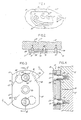
- the present safety strap assembly is generally indicated at 11 for interconnecting the adjacent contacting molds 13 and 15 for a plastic mold or die cast die.
- the respective molds-13 and 15 are in engagement side by side along a vertical parting line 17, for illustration, and a pair of laterally spaced shoulder bolts 19 are threaded into or otherwise secured to the respective molds 13 and 15 over which the present safety strap assembly 11 is assemblied and secured.
- shoulder straps are essentially employed between a pair of dies such as the dies 13 and 15 which are arranged side by side at their parting line 17 and are retained against lateral separation by accident such as for transporting in a plant or shipping purposes.
- the present shoulder bolt 19 includes a threaded shank 21 which is threaded into a drilled and tapped aperture within the corresponding molds 13 and 15 and a portion of the cylindrical shoulder 23 is snugly nested within a counterbore within the molds with a major portion of the cylindrical shoulder projecting outwardly of the molds and received by locking plate 29.
- Each of the shoulder bolts includes a head 25 at its outer end of increased diameter with respect to shoulder 23 and wherein there is an axially arranged Allen socket 27.
- the present safety strap assembly includes the elongated metallic locking plate 29, preferably steel, and over which is superimposed the locating cover 31 of a plastic material. Said cover is pivotably connected centrally to locking plate 29 by rivet 33, which extends through and retainingly engages the locating cover and extends through and retainingly engages an undersurface portion of the locking plate, figure 7.
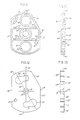
- the elongated locking plate 29 includes a pair of diametrically spaced apertures 35 with a diameter greater than shoulder bolt head 25 and extends upon a radius 43 arranged at an angle of 30 degrees with respect to the central axis 37.
- the center 39 of locking plate 29 is arranged along central axis 37 and provides a center for the opposed keyhole slots 41 which provide arcuate extensions of the respective apertures 35 adjacent opposite ends of locking plate 29.
- the corresponding radius 43 for apertures 35 as well as the keyhole slots 41 extends along an axis in the illustrative embodiment at 30 degrees with respect to central axis 37.
- Locking plate 29 has a pair of opposed parallel sides 45 with one of the sides terminating in tapered edge 47, which in the illustrative embodiment is inclined at a 30 degree angle with respect to central axis 37 or the corresponding straight side 45.
- Tapered edge 47 provides a detent clearance in the assembly shown in figure 3 relative to detent 79.
- the respective arcuate ends 49 are equidistant from center 39 through which is directed rivet aperture 51.
- the locating 31 cover shown in assembly figures 3 and 6 with respect to locking plate 29 is separately illustrated in figures 9, 10 and 11.
- Said cover includes a pair of centrally arranged spaced apertures 55 of a diameter greater than heads 25 of shoulder bolts 19. Said apertures are secured along central axis 57 of locating cover 31.
- Said cover has a center at 59 through which extends bore 61 and couter bore 63 defining the intermediate shoulder 65.
- Said shoulder is adapted to supportably receive rivet 33 for projection therethrough as in figure 7.
- Locating cover 31 has a pair of opposed parallel straight sides 67 equidistant from central axis 57 with one of the sides terminating in the inwardly tapered edge 69, which in the illustrative embodiment extends at an angle of 30 degrees with respect to axis 57.
- the locating cover 31 is of a moulded plastic material and as shown in figure 11 includes as extensions of apertures 55 the parallel sleeves 71. Their outer ends are coplanar with the peripheral flange 73 and the transverse ribs 75.
- a plurality of interference spacer bosses 77 Spaced outwardly of the plane which includes the outer surface of flange 73, the ribs 75 and sleeves 71 are a plurality of interference spacer bosses 77. These are shown in figure 10 as projecting outwardly of said plane adapted for cooperative registry with the adjacent surface of the locking plate when assemblied figures 3 through 8.
- first detent 79 which projects outwardly of the plane of peripheral flange 73, sleeves 71 and ribs 75. In the locking position of the safety strap assembly Figure 1, said detent is in registry with the corresponding tapered surface 45 figures 3 and 5.
- first detent 79 Diametrically opposed to first detent 79 upon the undersurface of locating cover 31 is a second detent 81 which projects outwardly of said plane.
- detent 81 In the locking position of the safety strap assembly, figure 3, detent 81 is in registry with the corresponding detent aperture 53 in locking plate figures 3 and 12.
- the safety strap assembly 11 has a locking position, figures 3 and 4 wherein locking plate 29 is so rotated that the respective keyhole slots 41 cooperatively receive the corresponding cylindrical shoulders 23 of shoulder bolts 19. At the same time the corresponding heads 25 of said shoulder bolts retainingly engage locking plate 29. Said heads extend outwardly and are enclosed within corresponding apertures 55 of locating plate 31. In the illustrative embodiment and regardless of whether the safety strap assembly is in a locking position, figure 3, or nonlocking position figure 6, locating plate 31 remains in the relative upright position shown.
- the locking plate 29 may be rotated 30 degrees, for illustration, counter clockwise from the position shown in figure 6 so as to create an interlock of the locking plate with the adjacent pair of shoulder bolts 19 upon the single die 15. This provides a means for anchoring the safety strap assembly upon one of the dies, such as die 15, after the safety strap has been removed from its connection between the respective dies.
Landscapes
- Engineering & Computer Science (AREA)
- Mechanical Engineering (AREA)
- General Engineering & Computer Science (AREA)
- Manufacturing & Machinery (AREA)
- Robotics (AREA)
- Moulds For Moulding Plastics Or The Like (AREA)
- Buckles (AREA)
Applications Claiming Priority (2)
| Application Number | Priority Date | Filing Date | Title |
|---|---|---|---|
| US53799 | 1987-05-26 | ||
| US07/053,799 US4773788A (en) | 1987-05-26 | 1987-05-26 | Safety strap assembly for molds and die cast dies |
Publications (2)
| Publication Number | Publication Date |
|---|---|
| EP0293174A2 true EP0293174A2 (de) | 1988-11-30 |
| EP0293174A3 EP0293174A3 (de) | 1990-07-04 |
Family
ID=21986618
Family Applications (1)
| Application Number | Title | Priority Date | Filing Date |
|---|---|---|---|
| EP88304711A Withdrawn EP0293174A3 (de) | 1987-05-26 | 1988-05-25 | Sicherungsblech für Formen oder Matrizen |
Country Status (3)
| Country | Link |
|---|---|
| US (1) | US4773788A (de) |
| EP (1) | EP0293174A3 (de) |
| CA (1) | CA1280269C (de) |
Cited By (1)
| Publication number | Priority date | Publication date | Assignee | Title |
|---|---|---|---|---|
| WO1997032679A1 (en) * | 1996-03-08 | 1997-09-12 | Aeroquip Corporation | Crimper assembly |
Families Citing this family (21)
| Publication number | Priority date | Publication date | Assignee | Title |
|---|---|---|---|---|
| US4881850A (en) * | 1988-09-01 | 1989-11-21 | Abreo Jr William A | Subsea guidebase |
| US5141386A (en) * | 1990-09-28 | 1992-08-25 | Barwise Robert D | Load handling apparatus with separable load coupling |
| US6094797A (en) * | 1992-03-16 | 2000-08-01 | Aircraft Parts Corporation | Apparatus and method for installing a starter-generator on an aircraft engine |
| US5257525A (en) * | 1992-06-24 | 1993-11-02 | Atco Products, Inc. | Portable slim-line hose fitting crimper |
| US5507199A (en) * | 1994-01-18 | 1996-04-16 | Grand Haven Stamped Products | Shifter with locking cover |
| US5762310A (en) * | 1996-02-09 | 1998-06-09 | Schill; Francine E. | Infant seat support with a resting surface having an adjustable height |
| JP3248841B2 (ja) * | 1996-02-29 | 2002-01-21 | 三菱電機株式会社 | アンテナマウント |
| US6416248B1 (en) * | 1998-01-22 | 2002-07-09 | Flexco | Quick release delineator apparatus |
| WO1999054634A1 (en) * | 1998-04-20 | 1999-10-28 | Globe Products, Inc. | Quick-change winding form assembly |
| US6616369B2 (en) * | 1999-01-20 | 2003-09-09 | Flexco | Quick release delineator apparatus |
| US6213631B1 (en) * | 1999-12-30 | 2001-04-10 | Barbara J. Miranda | Adapter for sealant tube |
| US6398179B1 (en) | 2000-01-19 | 2002-06-04 | General Motors Corporation | Fastener-less spring assembly |
| US6799579B2 (en) * | 2003-01-29 | 2004-10-05 | James R. Joseph | Fingernail and toenail shaping apparatus |
| CN101223399B (zh) * | 2005-06-09 | 2012-04-18 | 山田明 | 通路块的结合装置 |
| US7731443B2 (en) * | 2007-04-03 | 2010-06-08 | International Truck Intellectual Property Company, Llc | Mounting system for modular frame components |
| TR201103641A2 (tr) * | 2011-04-14 | 2012-11-21 | General Electric Company | Elektrik makine bileşeni montaj aparatı |
| CN102878156A (zh) * | 2011-07-13 | 2013-01-16 | 中国航空工业集团公司沈阳发动机设计研究所 | 一种安装边连接装置 |
| US9843849B1 (en) * | 2016-10-25 | 2017-12-12 | Christian Lasnier de Lavalette | Speaker mounting |
| CN107053544B (zh) * | 2017-06-07 | 2024-01-02 | 佛山市南海奔达模具有限公司 | 具有锁合机构的模具 |
| IT201800006169A1 (it) * | 2018-06-08 | 2019-12-08 | Apparato e procedimento per il campionamento dello spazio di testa dotato di uno o più sensori | |
| US20250339999A1 (en) * | 2024-05-06 | 2025-11-06 | Progressive Components International Corporation | Safety strap for injection molds |
Family Cites Families (9)
| Publication number | Priority date | Publication date | Assignee | Title |
|---|---|---|---|---|
| US1691676A (en) * | 1926-05-18 | 1928-11-13 | Smith Ernest Robert | Dental impression tray |
| FR638058A (fr) * | 1927-07-20 | 1928-05-15 | Dispositif de serrage de moule en deux parties | |
| BE481829A (de) * | 1948-04-13 | |||
| US2647294A (en) * | 1949-09-23 | 1953-08-04 | Frank L Davis | Releasable fastener |
| US4350481A (en) * | 1981-03-11 | 1982-09-21 | Corea John E | Apparatus for centrifugal casting of thermosetting plastics |
| DE3215567C2 (de) * | 1982-04-26 | 1996-07-11 | Battenfeld Gmbh | Schnellwechsel- und/oder Spannvorrichtung für die Formwerkzeuge von Druck- oder Spritzgießmaschinen |
| US4515037A (en) * | 1983-04-01 | 1985-05-07 | Kohler Co. | Handle assembly |
| US4487564A (en) * | 1983-04-29 | 1984-12-11 | Holdt J W Von | Split mold lock |
| DE8509642U1 (de) * | 1985-03-30 | 1985-07-18 | Wörner, Alois, 7580 Bühl | Werkzeug mit Einhängeöse, insbesondere aus zwei Formhälften bestehende Spritzgießform |
-
1987
- 1987-05-26 US US07/053,799 patent/US4773788A/en not_active Expired - Fee Related
-
1988
- 1988-03-29 CA CA000562858A patent/CA1280269C/en not_active Expired - Fee Related
- 1988-05-25 EP EP88304711A patent/EP0293174A3/de not_active Withdrawn
Cited By (1)
| Publication number | Priority date | Publication date | Assignee | Title |
|---|---|---|---|---|
| WO1997032679A1 (en) * | 1996-03-08 | 1997-09-12 | Aeroquip Corporation | Crimper assembly |
Also Published As
| Publication number | Publication date |
|---|---|
| CA1280269C (en) | 1991-02-19 |
| EP0293174A3 (de) | 1990-07-04 |
| US4773788A (en) | 1988-09-27 |
Similar Documents
| Publication | Publication Date | Title |
|---|---|---|
| US4773788A (en) | Safety strap assembly for molds and die cast dies | |
| US5201858A (en) | Quick-release connector | |
| US4946127A (en) | Theft resistant rotatable mount for computer consoles and the like | |
| US5946952A (en) | Lock cover system | |
| US4918820A (en) | Foldable pocket saw | |
| US5054170A (en) | Connector engageable in multiple positions and releasable in only one position | |
| US4987639A (en) | Frangible fastening construction for handles and method of fastening | |
| JPS6145032Y2 (de) | ||
| US4472128A (en) | Quick change locator clamp assembly for plastic molding machine | |
| US5113727A (en) | Pliers with removable jaw inserts | |
| US5544506A (en) | Auxiliary lock | |
| JPH0441234B2 (de) | ||
| US3963361A (en) | Shaft attachment assembly | |
| JPH0530448Y2 (de) | ||
| US4915342A (en) | Chain anchor clamp device | |
| US4687393A (en) | Centering pin with ovaloid point | |
| GB2251652A (en) | Panel hole closure assembly | |
| JPS6336221Y2 (de) | ||
| US5741145A (en) | Locking mechanism for an electrical connecting device | |
| CA1107528A (en) | Closure cap device for a fuel tank of a motorcycle | |
| US4426098A (en) | Head assembly for a towing device | |
| EP4206422B1 (de) | Verriegelungsmechanismus für schranktüren | |
| US6282758B1 (en) | Lock assembly for a roller-blades | |
| US4227707A (en) | Ski locking device | |
| JPS639155Y2 (de) |
Legal Events
| Date | Code | Title | Description |
|---|---|---|---|
| PUAI | Public reference made under article 153(3) epc to a published international application that has entered the european phase |
Free format text: ORIGINAL CODE: 0009012 |
|
| AK | Designated contracting states |
Kind code of ref document: A2 Designated state(s): DE FR GB IT SE |
|
| PUAL | Search report despatched |
Free format text: ORIGINAL CODE: 0009013 |
|
| AK | Designated contracting states |
Kind code of ref document: A3 Designated state(s): DE FR GB IT SE |
|
| STAA | Information on the status of an ep patent application or granted ep patent |
Free format text: STATUS: THE APPLICATION IS DEEMED TO BE WITHDRAWN |
|
| 18D | Application deemed to be withdrawn |
Effective date: 19910105 |