EP0437398A2 - Diebstahlsicherer drehbarer Standfuss für Rechnerkonsolen und dergleichen - Google Patents
Diebstahlsicherer drehbarer Standfuss für Rechnerkonsolen und dergleichen Download PDFInfo
- Publication number
- EP0437398A2 EP0437398A2 EP91400038A EP91400038A EP0437398A2 EP 0437398 A2 EP0437398 A2 EP 0437398A2 EP 91400038 A EP91400038 A EP 91400038A EP 91400038 A EP91400038 A EP 91400038A EP 0437398 A2 EP0437398 A2 EP 0437398A2
- Authority
- EP
- European Patent Office
- Prior art keywords
- section
- mount
- lower section
- stud
- sections
- Prior art date
- Legal status (The legal status is an assumption and is not a legal conclusion. Google has not performed a legal analysis and makes no representation as to the accuracy of the status listed.)
- Withdrawn
Links
- 238000000926 separation method Methods 0.000 claims description 2
- 230000002401 inhibitory effect Effects 0.000 claims 1
- 239000000945 filler Substances 0.000 description 2
- 238000010276 construction Methods 0.000 description 1
- 230000006378 damage Effects 0.000 description 1
- 230000001419 dependent effect Effects 0.000 description 1
- 230000001066 destructive effect Effects 0.000 description 1
- 230000013011 mating Effects 0.000 description 1
- 238000000034 method Methods 0.000 description 1
- 238000012986 modification Methods 0.000 description 1
- 230000004048 modification Effects 0.000 description 1
Images
Classifications
-
- E—FIXED CONSTRUCTIONS
- E05—LOCKS; KEYS; WINDOW OR DOOR FITTINGS; SAFES
- E05B—LOCKS; ACCESSORIES THEREFOR; HANDCUFFS
- E05B73/00—Devices for locking portable objects against unauthorised removal; Miscellaneous locking devices
- E05B73/0082—Devices for locking portable objects against unauthorised removal; Miscellaneous locking devices for office machines, e.g. PC's, portable computers, typewriters, calculators
-
- F—MECHANICAL ENGINEERING; LIGHTING; HEATING; WEAPONS; BLASTING
- F16—ENGINEERING ELEMENTS AND UNITS; GENERAL MEASURES FOR PRODUCING AND MAINTAINING EFFECTIVE FUNCTIONING OF MACHINES OR INSTALLATIONS; THERMAL INSULATION IN GENERAL
- F16M—FRAMES, CASINGS OR BEDS OF ENGINES, MACHINES OR APPARATUS, NOT SPECIFIC TO ENGINES, MACHINES OR APPARATUS PROVIDED FOR ELSEWHERE; STANDS; SUPPORTS
- F16M11/00—Stands or trestles as supports for apparatus or articles placed thereon ; Stands for scientific apparatus such as gravitational force meters
- F16M11/02—Heads
- F16M11/04—Means for attachment of apparatus; Means allowing adjustment of the apparatus relatively to the stand
- F16M11/06—Means for attachment of apparatus; Means allowing adjustment of the apparatus relatively to the stand allowing pivoting
- F16M11/08—Means for attachment of apparatus; Means allowing adjustment of the apparatus relatively to the stand allowing pivoting around a vertical axis, e.g. panoramic heads
-
- F—MECHANICAL ENGINEERING; LIGHTING; HEATING; WEAPONS; BLASTING
- F16—ENGINEERING ELEMENTS AND UNITS; GENERAL MEASURES FOR PRODUCING AND MAINTAINING EFFECTIVE FUNCTIONING OF MACHINES OR INSTALLATIONS; THERMAL INSULATION IN GENERAL
- F16M—FRAMES, CASINGS OR BEDS OF ENGINES, MACHINES OR APPARATUS, NOT SPECIFIC TO ENGINES, MACHINES OR APPARATUS PROVIDED FOR ELSEWHERE; STANDS; SUPPORTS
- F16M2200/00—Details of stands or supports
- F16M2200/02—Locking means
-
- F—MECHANICAL ENGINEERING; LIGHTING; HEATING; WEAPONS; BLASTING
- F16—ENGINEERING ELEMENTS AND UNITS; GENERAL MEASURES FOR PRODUCING AND MAINTAINING EFFECTIVE FUNCTIONING OF MACHINES OR INSTALLATIONS; THERMAL INSULATION IN GENERAL
- F16M—FRAMES, CASINGS OR BEDS OF ENGINES, MACHINES OR APPARATUS, NOT SPECIFIC TO ENGINES, MACHINES OR APPARATUS PROVIDED FOR ELSEWHERE; STANDS; SUPPORTS
- F16M2200/00—Details of stands or supports
- F16M2200/08—Foot or support base
-
- Y—GENERAL TAGGING OF NEW TECHNOLOGICAL DEVELOPMENTS; GENERAL TAGGING OF CROSS-SECTIONAL TECHNOLOGIES SPANNING OVER SEVERAL SECTIONS OF THE IPC; TECHNICAL SUBJECTS COVERED BY FORMER USPC CROSS-REFERENCE ART COLLECTIONS [XRACs] AND DIGESTS
- Y10—TECHNICAL SUBJECTS COVERED BY FORMER USPC
- Y10S—TECHNICAL SUBJECTS COVERED BY FORMER USPC CROSS-REFERENCE ART COLLECTIONS [XRACs] AND DIGESTS
- Y10S248/00—Supports
- Y10S248/917—Video display screen support
- Y10S248/919—Adjustably orientable video screen support
- Y10S248/922—Angular
Definitions
- the present invention relates to a theft-resistant mount for rotatably mounting an instrument such as a computer console or the like on a stand or other support.
- a rotatable, theft-resistant mount for office instruments such as computer consoles in accordance with the invention comprises a base having two vertically stacked sections.
- the lower section is generally circular with a depression in the middle of its upper surface.
- the upper section has a matching circular surface defined by a depending rim which nests over the circular lower section, and a depending stud rotatably affixed in its lower surface which mates with the depression in the upper surface of the lower section.
- the lower section is also provided with a diametrical tubular passage passing through the central depression.
- the depending stud affixed to the upper section is provided with a hole through which an elongated locking rod positioned within the tubular passage extends, thus preventing the upper section of the base from being separated from the lower section, while permitting relative rotation of the two sections. It is preferred to position a rotary bearing between the contiguous surfaces of the upper and lower sections to permit the sections to rotate freely relative to each other without binding or wobbling.
- the lower section of the base is rigidly attached to a stand or other support by means passing through its upper surface downwardly into the stand.
- the object to be supported hereinafter the "instrument" is attached to the upper base by means passing upwardly through the lower surface of the upper base.
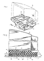
- the theft-resistant rotatable mount 10 of the invention comprises two sections which can be separated when desired but which in normal operation are interconnected to permit relative rotation thereof.
- Mount 10 comprises a generally circular plate-like lower section 11 and an upper section 12 having a corresponding circular surface defined in part by a circular depending rim 13 sized to nest snugly over the outer edge of the lower section.
- Attached to the upper portion, upper section 12 is a mounting plate 14 having a surface 16 adapted to receive the instrument 15 to be supported.
- the particular configuration of surface 16 depends on the identity and nature of the instrument and does not per se form a part of the invention.
- upper surface 16 of plate 14 is provided with rectangular grooves 17 and circular depressions 18 adapted to receive a particular model of computer console. Surface 16 could have a different configuration appropriate for use with other instruments.
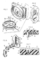
- a depending stud 21 Attached to the center of the lower circular surface 19 in upper section 12 is a depending stud 21 which freely rotates in place but which cannot be removed when the mount is assembled except by application of destructive force. Stud 21 is provided with a transverse hole 22 which extends completely through the thickness of the stud.
- the upper surface 23 of lower section 12 is provided at its center with a recess 24 adapted to receive stud 21 and thus to permit sections 11 and 12 to nest snugly together.
- Lower section 11 is also provided with a tubular passage 26 extending diametrically through recess 24, into which an elongated locking pin 27 can be inserted. It is preferred to provide both recess 24 and stud 21 with mating noncircular, cross-sectional outlines such that when stud 21 is inserted into recess 24, the stud is oriented in a position causing hole 22 to be aligned with passage 26, permitting locking pin 27, inserted through an appropriately situated opening 25 in rim 13 to pass through stud 21.
- the end of locking pin 27 which is inserted into tubular passage 26 is provided with means, e.g., threads 28, for engaging a locking means 29 (figure 2) located within tubular passage 26 at a point opposite its entrance.
- locking means 29 is represented by a threaded nut 31 into which the threads 28 of pin 27 are received.
- the opposite end of pin 27 is provided with means (not shown) for rotating the pin into locking engagement with nut 31.
- the rotating means in the end of the pin a nonstandard shape or form, requiring a specially designed driver, the particular nature of which is not critical.
- it is desirable to have its end when completely inserted lie entirely within passage 26 and substantially below the outer surface of lower section 11.
- FIG. 4 One embodiment of suitable means for rotatably attaching stud 21 to upper section 12 is illustrated in figures 4, 5 and 6.
- the invention is, of course, not restricted to the particular means shown in these drawings since other suitable mechanical embodiments will be apparent to those skilled in the art.
- lower surface 19 of upper section 12 is provided with a slot 32 having an enlarged circular portion 33 at one end, to which is joined a narrower slot 34 provided with an undercut portion 36 having a width equal to the diameter of the circular portion 33.
- Stud 21 is provided at one end with a circular flange 37 which can be inserted in circular portion 33 of slot 32.
- a resilient washer 38 having an inner diameter equal to that of the diameter of stud 21 is then slipped over the stud and the assembly is moved vertically, as shown in figure 4, to the narrow upper end of slot 32.
- a resilient filler plug 39 is then inserted in the open portion of the slot, thus preventing the removal of the stud assembly from the surface. It will be seen that in the condition shown in figure 6, stud 21 can rotate freely relative to upper section 12 but cannot be separated therefrom without destruction of the assembly or removal of washer 38 and filler plug 39.
- fastening means e.g. screws or bolts 42 as shown in figures 2 and 3, which when installed are covered by the upper section 12 of the mount. As shown in figure 2, screws 42 pass through lower section 11 and into the stand and cannot be removed to release the assembled base 10 without first removing upper section 12.
- attaching means e.g. bolt 43 (figure 7), which pass vertically through plate 14 of upper section 12 into instrument 15.
- attaching means 43 are covered and cannot be easily removed.
- mount 10 will be obvious from the description which has been given. After lower section 11 of the mount is attached to stand 44, and the upper section 12 of the mount is attached to instrument 15, as described, the upper and lower sections are nested together, and locking pin 27 is inserted into tubular passage 26 through the opening 25 in rim 13, through stud 21 and into engagement with nut 31 on the far side of the passage. The two sections of the mount are thus interconnected to prevent separation thereof while permitting free rotation.
- the outer rim of lower section 11 may be provided with a plurality of relatively shallow holes 46 (figure 3) having a size similar to that of opening 25 in rim 13 in upper section 12 and located so as to register with opening 25.
- a positioning pin 47 By rotating the upper section to the desired location and with opening 25 in registry with a desired one of openings 46 in the lower section, a positioning pin 47 can be inserted through rim 13 into lower section 11, holding upper section 12 in the desired position.
Landscapes
- Engineering & Computer Science (AREA)
- General Engineering & Computer Science (AREA)
- Computer Hardware Design (AREA)
- Mechanical Engineering (AREA)
- Casings For Electric Apparatus (AREA)
- Connection Of Plates (AREA)
Applications Claiming Priority (2)
| Application Number | Priority Date | Filing Date | Title |
|---|---|---|---|
| US464527 | 1990-01-12 | ||
| US07/464,527 US4946127A (en) | 1990-01-12 | 1990-01-12 | Theft resistant rotatable mount for computer consoles and the like |
Publications (2)
| Publication Number | Publication Date |
|---|---|
| EP0437398A2 true EP0437398A2 (de) | 1991-07-17 |
| EP0437398A3 EP0437398A3 (en) | 1992-04-22 |
Family
ID=23844289
Family Applications (1)
| Application Number | Title | Priority Date | Filing Date |
|---|---|---|---|
| EP19910400038 Withdrawn EP0437398A3 (en) | 1990-01-12 | 1991-01-10 | Theft resistant rotatable mount for computer consoles and the like |
Country Status (3)
| Country | Link |
|---|---|
| US (1) | US4946127A (de) |
| EP (1) | EP0437398A3 (de) |
| CA (1) | CA2033824A1 (de) |
Cited By (1)
| Publication number | Priority date | Publication date | Assignee | Title |
|---|---|---|---|---|
| CN104279415A (zh) * | 2013-05-21 | 2015-01-14 | 罗斯蒙特航天公司 | 旋转式电子显示适配器 |
Families Citing this family (33)
| Publication number | Priority date | Publication date | Assignee | Title |
|---|---|---|---|---|
| GB2239390B (en) * | 1989-12-11 | 1994-01-19 | Titus Tool Co Ltd | Turntable |
| DE9006002U1 (de) | 1990-05-26 | 1990-08-02 | Grundmann, Ernst H., 4005 Meerbusch | Drehtellereinrichtung |
| US5169116A (en) * | 1991-07-19 | 1992-12-08 | Bergetz Carl A | Mounting lug for television or similar appliance |
| US5150482A (en) * | 1991-07-25 | 1992-09-29 | Leo Shapiro | Bath chair swivel foot |
| US5383641A (en) * | 1992-10-27 | 1995-01-24 | Peerless Industries, Inc. | Television support member security mounting assembly |
| US5479867A (en) * | 1993-10-12 | 1996-01-02 | Blevins; Bruce D. | Rotary table |
| USD361990S (en) | 1993-11-05 | 1995-09-05 | International Business Machines Corporation | Computer stand |
| USD358381S (en) | 1993-11-05 | 1995-05-16 | International Business Machines Corporation | Computer stand |
| USD368706S (en) | 1994-04-28 | 1996-04-09 | International Business Machines Corporation | Monitor pedestal |
| US5564669A (en) * | 1995-02-03 | 1996-10-15 | Acer Peripherals, Inc. | Base support of a display device capable of moving on a surface |
| GB2306191A (en) * | 1995-10-11 | 1997-04-30 | Delta 3 Ltd | A device for securing portable equipment |
| DE19633003A1 (de) * | 1996-08-16 | 1998-02-19 | Philips Patentverwaltung | Vorrichtung zur drehbaren Lagerung von Gegenständen um eine Drehachse |
| KR100255765B1 (ko) * | 1997-07-09 | 2000-05-01 | 구자홍 | 영상표시기기의 전후 조절 받침대 구조 |
| US6095476A (en) * | 1998-02-12 | 2000-08-01 | Mathis; Virgil | Adjustable television stand |
| US6178089B1 (en) | 1998-07-15 | 2001-01-23 | Dell U.S.A., L.P. | Securing device for computer equipment housing |
| CN1121001C (zh) * | 1998-12-14 | 2003-09-10 | 卡路事务器株式会社 | 臂垫 |
| US6062523A (en) * | 1999-01-28 | 2000-05-16 | Lu; William | Structure of a rotatable base for computer monitors |
| US6474614B2 (en) | 2000-07-05 | 2002-11-05 | Road Tools Llc | Heat dissipating laptop computer stand with adjustable tilt |
| US7481410B2 (en) * | 2002-06-24 | 2009-01-27 | Business Machines Security, Inc. | Equipment security apparatus |
| US6959901B2 (en) * | 2003-12-04 | 2005-11-01 | Chun Yuan Chang | Rotatable book or file holder device |
| KR100710078B1 (ko) * | 2005-06-13 | 2007-04-23 | 삼성전자주식회사 | 모니터장치 |
| US7360748B2 (en) * | 2005-09-01 | 2008-04-22 | Suncast Corporation | Rotary table for enclosed hose reel |
| US8082944B2 (en) | 2005-09-01 | 2011-12-27 | Suncast Corporation | Pivotal base for enclosed hose reel |
| TWI325038B (en) * | 2006-08-11 | 2010-05-21 | Au Optronics Corp | Variable revolving position device |
| US7644903B2 (en) * | 2007-01-19 | 2010-01-12 | Metra Electronics | Rotating pedestal with lock |
| EP2115341A1 (de) * | 2007-02-02 | 2009-11-11 | Bang & Olufsen A/S | Träger für multimedieneinheiten |
| US20080197246A1 (en) * | 2007-02-20 | 2008-08-21 | Alpha Security Products, Inc. | Adapter for article display stand |
| US7576276B2 (en) * | 2007-12-31 | 2009-08-18 | Hallerberg Dale A | Percussion instrument spinner |
| US20100050706A1 (en) * | 2008-09-03 | 2010-03-04 | Lucasey Manufacturing Company | Releasable security mount |
| GB2479895A (en) * | 2010-04-28 | 2011-11-02 | Wincor Nixdorf Ltd | A plinth for securing an object to a base |
| US8616268B2 (en) * | 2010-07-15 | 2013-12-31 | Preston Industries, Inc. | Movable constant temperature circulator assembly |
| US8851413B2 (en) | 2012-11-02 | 2014-10-07 | Suncast Technologies, Llc | Reel assembly |
| GB201517487D0 (en) | 2015-10-03 | 2015-11-18 | Choquette Samuel | Rotatable platter for visual display having a passage for wiring and a stopper |
Family Cites Families (13)
| Publication number | Priority date | Publication date | Assignee | Title |
|---|---|---|---|---|
| US3291432A (en) * | 1965-01-22 | 1966-12-13 | Joseph A Lucasey | Mounting arrangement for television receivers and the like |
| US3321165A (en) * | 1965-08-06 | 1967-05-23 | Sylvania Electric Prod | Tv table mount |
| NL6516278A (de) * | 1965-12-14 | 1967-06-15 | ||
| DE1973567U (de) * | 1967-07-12 | 1967-11-30 | Braun Ag | Drehgestell. |
| US3908942A (en) * | 1974-04-25 | 1975-09-30 | Morton Metalcraft Co | Mounting means for television sets and the like |
| US4143927A (en) * | 1977-10-21 | 1979-03-13 | Market Forge, A Division Of Beatrice Foods Co. | Cassette locking device |
| US4305266A (en) * | 1979-12-21 | 1981-12-15 | Lockwood Robert G | Locking apparatus for portable devices |
| US4542872A (en) * | 1983-02-09 | 1985-09-24 | Prime Computer, Inc. | Terminal with tilt-swivel display |
| US4579311A (en) * | 1983-11-16 | 1986-04-01 | Spranza Iii Joseph J | Equipment lockdown apparatus |
| US4613109A (en) * | 1984-03-19 | 1986-09-23 | Lucasey Manufacturing Company | Appliance security device |
| US4635894A (en) * | 1985-06-17 | 1987-01-13 | Fournier Accessory Furniture, Inc. | Multi-purpose furniture swivel assembly |
| JPS6221923U (de) * | 1985-07-25 | 1987-02-09 | ||
| US4852830A (en) * | 1988-07-21 | 1989-08-01 | Apple Computer, Inc. | Computer moniter stand |
-
1990
- 1990-01-12 US US07/464,527 patent/US4946127A/en not_active Expired - Fee Related
-
1991
- 1991-01-09 CA CA002033824A patent/CA2033824A1/en not_active Abandoned
- 1991-01-10 EP EP19910400038 patent/EP0437398A3/en not_active Withdrawn
Cited By (2)
| Publication number | Priority date | Publication date | Assignee | Title |
|---|---|---|---|---|
| CN104279415A (zh) * | 2013-05-21 | 2015-01-14 | 罗斯蒙特航天公司 | 旋转式电子显示适配器 |
| CN104279415B (zh) * | 2013-05-21 | 2018-09-11 | 罗斯蒙特航天公司 | 旋转式电子显示适配器 |
Also Published As
| Publication number | Publication date |
|---|---|
| CA2033824A1 (en) | 1991-07-13 |
| EP0437398A3 (en) | 1992-04-22 |
| US4946127A (en) | 1990-08-07 |
Similar Documents
| Publication | Publication Date | Title |
|---|---|---|
| US4946127A (en) | Theft resistant rotatable mount for computer consoles and the like | |
| JP3682978B2 (ja) | 管等を圧締するクランプ装置 | |
| US5135197A (en) | Equipment security method and apparatus | |
| US6955515B2 (en) | Locking turn pin | |
| US4074941A (en) | Cam operated toggle for securing a light fixture or the like to a tube | |
| US4305266A (en) | Locking apparatus for portable devices | |
| DE60101167T2 (de) | Verriegelungsvorrichtung bedienbar ohne werkzeug | |
| KR20010040601A (ko) | 턴 파스너 | |
| EP0293174A2 (de) | Sicherungsblech für Formen oder Matrizen | |
| US5058838A (en) | Support for variably sized electrically energized tubing | |
| DE69918745T2 (de) | Handgriff und innenseitiger Kraftfahrzeugsgriff | |
| JPH07508089A (ja) | ネジ部材を係合するための方法および装置 | |
| AU3985089A (en) | Computer data drive locking device | |
| US6305890B1 (en) | Covering device for nut and covering device for bolt head | |
| US11358170B2 (en) | Sprinkler center bracket provided with locker for preventing loosening of cam lever coupled thereto | |
| DE19833157A1 (de) | Vorrichtung zur Befestigung und Ausrichtung eines Gerätes an einem Halterahmen | |
| US4111016A (en) | Locking fastener assembly | |
| US9933111B1 (en) | Electronics mount | |
| US20090242352A1 (en) | Rotation stop system | |
| EP0051766B1 (de) | Haltevorrichtung für elektrische Geräte, insbesondere für Einbruchdetektoren | |
| EP0825057B1 (de) | Vorrichtung zur drehbaren Lagerung von Gegenständen um eine Drehachse | |
| JP3353143B2 (ja) | 遊技機等における着脱施錠装置 | |
| US4227707A (en) | Ski locking device | |
| EP0365197A2 (de) | Befestigungsvorrichtung | |
| JP3125186B2 (ja) | 遊技機等における着脱用部材の着脱施錠装置 |
Legal Events
| Date | Code | Title | Description |
|---|---|---|---|
| PUAI | Public reference made under article 153(3) epc to a published international application that has entered the european phase |
Free format text: ORIGINAL CODE: 0009012 |
|
| AK | Designated contracting states |
Kind code of ref document: A2 Designated state(s): AT BE CH DE DK ES FR GB GR IT LI LU NL SE |
|
| PUAL | Search report despatched |
Free format text: ORIGINAL CODE: 0009013 |
|
| AK | Designated contracting states |
Kind code of ref document: A3 Designated state(s): AT BE CH DE DK ES FR GB GR IT LI LU NL SE |
|
| STAA | Information on the status of an ep patent application or granted ep patent |
Free format text: STATUS: THE APPLICATION IS DEEMED TO BE WITHDRAWN |
|
| 18D | Application deemed to be withdrawn |
Effective date: 19921023 |