US4915342A - Chain anchor clamp device - Google Patents
Chain anchor clamp device Download PDFInfo
- Publication number
- US4915342A US4915342A US07/255,666 US25566688A US4915342A US 4915342 A US4915342 A US 4915342A US 25566688 A US25566688 A US 25566688A US 4915342 A US4915342 A US 4915342A
- Authority
- US
- United States
- Prior art keywords
- anchor
- plate
- chain
- clamp device
- retainer cap
- Prior art date
- Legal status (The legal status is an assumption and is not a legal conclusion. Google has not performed a legal analysis and makes no representation as to the accuracy of the status listed.)
- Expired - Fee Related
Links
Images


Classifications
-
- B—PERFORMING OPERATIONS; TRANSPORTING
- B21—MECHANICAL METAL-WORKING WITHOUT ESSENTIALLY REMOVING MATERIAL; PUNCHING METAL
- B21D—WORKING OR PROCESSING OF SHEET METAL OR METAL TUBES, RODS OR PROFILES WITHOUT ESSENTIALLY REMOVING MATERIAL; PUNCHING METAL
- B21D1/00—Straightening, restoring form or removing local distortions of sheet metal or specific articles made therefrom; Stretching sheet metal combined with rolling
- B21D1/14—Straightening frame structures
- B21D1/145—Clamps therefor
-
- Y—GENERAL TAGGING OF NEW TECHNOLOGICAL DEVELOPMENTS; GENERAL TAGGING OF CROSS-SECTIONAL TECHNOLOGIES SPANNING OVER SEVERAL SECTIONS OF THE IPC; TECHNICAL SUBJECTS COVERED BY FORMER USPC CROSS-REFERENCE ART COLLECTIONS [XRACs] AND DIGESTS
- Y10—TECHNICAL SUBJECTS COVERED BY FORMER USPC
- Y10S—TECHNICAL SUBJECTS COVERED BY FORMER USPC CROSS-REFERENCE ART COLLECTIONS [XRACs] AND DIGESTS
- Y10S72/00—Metal deforming
- Y10S72/705—Vehicle body or frame straightener
Definitions
- This invention relates to a vehicle attachment device for a vehicle chassis straightening or aligning bench, and more particularly to a moveable chain anchor clamp which secures a vehicle to the straightening bench.
- Straightening or alignment benches are used to repair damaged vehicle frames and bodies. But before any straightening operation can be carried out, the vehicle must be secured to the frame of the straightening bench by attachment devices.
- attachment devices include chain anchor clamps which are fixed in various locations on the frame to secure chains connected to the vehicle frame.
- a chain anchor clamp device having an anchor plate which pivots about a generally vertical axis, slides generally transversely and is releasably securable to a straightening bench in any desired pivoted position.
- Objects, features and advantages of this invention are to provide a chain anchor clamp device for securing a chain connected to a vehicle to a straightening bench, which is capable of locking in any desired pivotal position and along the guide track, usable for many different vehicles, easy to set up and use, rugged, durable and of relatively simple and economical design, manufacture and assembly.
- FIG. 1 is a perspective view of a chassis straightening or aligning bench with chain anchor clamp devices embodying this invention
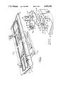
- FIG. 2 is an exploded perspective view of a chain anchor clamp device of FIG. 1;
- FIG. 3 is a top view of the chain anchor clamp device of FIGS. 1 and 2 with portions broken away for purposes of illustration;
- FIG. 4 is a sectional view taken along line 4--4 in FIG. 3;
- FIG. 5 a fragmentary end view of the vehicle chassis straightening bench of FIG. 1 with a lock plate inserted in the guide track with its position just before insertion shown in phantom;
- FIG. 6 is a fragmentary top view of the lock plate and track of FIG. 5;
- FIG. 7 is a fragmentary end view of the vehicle chassis straightening bench of FIG. 1 with the chain anchor clamp device securing a chain connected to a vehicle;
- FIG. 8 is an enlarged perspective view of a loc plate of the chain anchor clamp device of FIG. 1.
- FIGS. 1 and 2 illustrate a chain anchor clamp device 10 embodying this invention inserted into the recesses or grooves 12 and 14 in guide tracks 16 which are welded to the perimeter of the top surface of side beams 18 of a vehicle chassis straightening bench 20.
- clamp device 10 has an anchor plate 22 journaled for pivoting on a retainer cap 24 connected to a lock plate 26 by a pair of bolts 28.
- a hook 30 with a clevis 32 is pivotally connected by a pin 34 to a mounting block 36 fixed to the anchor plate.
- the anchor plate 22 is journaled for rotation on a cylindrical bearing 38 of a central hub 40 of the retainer 24 cap which is slidably received in a bore 42 through the anchor plate 22.
- the anchor plate 22 is retained on the hub 40 by a circumferentially continuous flange 44 of the cap 24.
- the chain anchor clamp device 10 is slidably received and releasably secured to the bench 20 by the cooperation of the retainer cap 24, lock plate 26 and bolts 28.
- the bolts 28 are received in guide bores 46 of the retainer cap 24 and engage lock plate 26.
- the lock plate 26 has a central prominence or island 48 receivable between a pair of opposed channels or tracks 16 of the bench and a peripheral flange or shoulder 50 which projects into the grooves 12 and 14 in the tracks.
- the lock plate 26 is constructed so that it can be inserted from above the tracks into their grooves 12 and 14 as shown in FIG. 5, and then rotated 90° from the position shown in FIG. 6 to that shown in FIG. 3 to fully engage the flange 50 in the grooves 12 and 14.
- both guide flange portions 52 will project somewhat into the grooves 12 and 14 when the plate 26 is centered between the tracks 16.
- a pair of parallel lock flange portions 56 have their edges 58 transversely spaced apart sufficiently so that they extend further into the grooves 12 and 14 with their edges 58 closely adjacent to the bottoms of the grooves 12 and 14.
- the transverse spacing between the edges 58 is greater than the transverse spacing between the edges 54.
- edges 60 of edges 58 are rounded or curved.
- the lower edges 62 of the guide flanges 52 are beveled. As shown in FIG. 5, when the lock plate 26 is initially inserted in the grooves 12 and 14, it is centered between the tracks 16 by the beveled edges 62 and the upper face 64 of the flange 50 is spaced from the upper faces 66 of the grooves.
- the beveled edges 62 act as cams to lift the plate 26 so that the flange portions 56 are automatically aligned with and easily slide into the grooves 12 and 14 of the tracks 16, with the upper face 64 of the flange underlying the upper faces 66 of the grooves 12 and 14.
- the island 48 also has peripheral edges 68, 70 and 72 spaced inwardly of and complimentary to the peripheral edges 54, 58 and 60 of the flange 50.
- the anchor device 10 When the anchor device 10 is received on the tracks 16 of the bench 20 and the lock plate 26 is turned to its locked position, as shown in FIGS. 3 and 4, it can be releasably secured to the bench 20 by tightening bolts 28 which are received in complimentary threaded holes 74 through the lock plate 26.
- the lock plate 26 has a center locating hole 76 through it to facilitate its machining from a block of steel.
- the centers of the threaded holes 74 are on a center line of the locater hole 76 parallel to one of the edges of the flange such as an edge 58 and are equally spaced from the center of the locater hole 76.
- a vehicle is rolled onto the straightening bench 20 and chain anchor clamp devices 10 are installed into the guide tracks 16 beneath the vehicle.
- the clamp devices 10 are slid along the tracks 16 to the most convenient and advantageous position under the vehicle, then the lock plate 26 is rotated to its locked position by manually grasping the head of the bolts 28 and/or the retainer cap 24.
- the anchor plate 26 can be rotated 360° about this advantageous position.
- a chain 80 is then attached to the vehicle and hooked to the clevis 32 of the clamp device 10.
- the bolts 28 can be tightened down, drawing up the lock plate 26 and tightly engaging its upper flange surface 64 with the upper face 66 of the grooves 12 and 14. This also forces the retainer cap 24 onto the anchor plate 22 to hold it securely on the top of the guide tracks 16. This prevents the chain anchor clamp 10 from moving from the desired position.
Landscapes
- Engineering & Computer Science (AREA)
- Mechanical Engineering (AREA)
- Vehicle Cleaning, Maintenance, Repair, Refitting, And Outriggers (AREA)
Abstract
Description
Claims (5)
Priority Applications (1)
| Application Number | Priority Date | Filing Date | Title |
|---|---|---|---|
| US07/255,666 US4915342A (en) | 1988-10-11 | 1988-10-11 | Chain anchor clamp device |
Applications Claiming Priority (1)
| Application Number | Priority Date | Filing Date | Title |
|---|---|---|---|
| US07/255,666 US4915342A (en) | 1988-10-11 | 1988-10-11 | Chain anchor clamp device |
Publications (1)
| Publication Number | Publication Date |
|---|---|
| US4915342A true US4915342A (en) | 1990-04-10 |
Family
ID=22969361
Family Applications (1)
| Application Number | Title | Priority Date | Filing Date |
|---|---|---|---|
| US07/255,666 Expired - Fee Related US4915342A (en) | 1988-10-11 | 1988-10-11 | Chain anchor clamp device |
Country Status (1)
| Country | Link |
|---|---|
| US (1) | US4915342A (en) |
Cited By (18)
| Publication number | Priority date | Publication date | Assignee | Title |
|---|---|---|---|---|
| US5092587A (en) * | 1990-09-27 | 1992-03-03 | Ulner Eric R | Climbing system |
| US5139375A (en) * | 1990-07-05 | 1992-08-18 | Franchuk Robert J | Adjustable mounting system |
| US5201487A (en) * | 1992-04-17 | 1993-04-13 | Epplett Richard E | Vehicular rooftop rail mount-to-gutter mount adaptor system |
| US6568237B1 (en) * | 2000-08-08 | 2003-05-27 | Hein-Werner Corporation | Apparatus and method for vehicle manipulative anchoring |
| US20040099039A1 (en) * | 2002-11-21 | 2004-05-27 | Michael Marx | Deck leverage anchor |
| US20040131440A1 (en) * | 2003-01-03 | 2004-07-08 | Nissan Technical Center North America, Inc. | Track slot fastener |
| US20040131439A1 (en) * | 2003-01-03 | 2004-07-08 | Nissan Technical Center North America, Inc. | Track slot fastener |
| US20040200258A1 (en) * | 2003-04-08 | 2004-10-14 | Hess Jeffrey A. | Locking mechanism for jack with elevated platform |
| US20050108958A1 (en) * | 2003-11-21 | 2005-05-26 | Michael Marx | Deck leverage anchor with swivel mechanism |
| US20050117991A1 (en) * | 2000-10-25 | 2005-06-02 | Nissan Design America, Inc. | Flexible truck bed tie-down system |
| US7032866B1 (en) * | 2003-05-15 | 2006-04-25 | Cummins, Inc. | Bracket with captured spacer |
| US20080028820A1 (en) * | 2006-07-18 | 2008-02-07 | Browning Christopher L | Frame rail pulling apparatus |
| US20080116344A1 (en) * | 2006-09-11 | 2008-05-22 | Robert Whitt | Quick-release mounting bracket for a hand truck |
| US20090080995A1 (en) * | 2007-09-20 | 2009-03-26 | Nissan Technical Center North America, Inc. | Vehicle cargo arrangement |
| CN102950172A (en) * | 2012-11-07 | 2013-03-06 | 浙江弘道科技有限公司 | Correction method and device of flatness of metal plate |
| US9162271B2 (en) | 2010-10-08 | 2015-10-20 | Michael J. Marx | Deck leverage anchor with spaced-apart body portions |
| US20160297503A1 (en) * | 2015-04-07 | 2016-10-13 | Andre Smit | Mounting system and associated apparatus |
| US20220017021A1 (en) * | 2020-07-17 | 2022-01-20 | Wild West Investments, LLC | Clamp assembly for mounting a mobile device |
Citations (7)
| Publication number | Priority date | Publication date | Assignee | Title |
|---|---|---|---|---|
| US2688289A (en) * | 1952-02-08 | 1954-09-07 | Pan American World Airways Inc | Cargo tie-down assembly |
| US3381925A (en) * | 1966-09-02 | 1968-05-07 | Davis Aircraft Products Inc | Tiedown fitting for ship decks |
| US3432197A (en) * | 1966-06-30 | 1969-03-11 | Mc Donnell Douglas Corp | Slider latch |
| US3722910A (en) * | 1971-04-21 | 1973-03-27 | H Heckenlaible | Hook unit for pickup trucks |
| US3779502A (en) * | 1972-04-03 | 1973-12-18 | B Marberg | Stake pocket tie down insert |
| US3888190A (en) * | 1974-01-10 | 1975-06-10 | Henry W Bigge | Tiedown lug |
| US4708549A (en) * | 1986-05-01 | 1987-11-24 | Ancra Corporation | Rattle-proof anchor fitting for securing loads to retainer track |
-
1988
- 1988-10-11 US US07/255,666 patent/US4915342A/en not_active Expired - Fee Related
Patent Citations (7)
| Publication number | Priority date | Publication date | Assignee | Title |
|---|---|---|---|---|
| US2688289A (en) * | 1952-02-08 | 1954-09-07 | Pan American World Airways Inc | Cargo tie-down assembly |
| US3432197A (en) * | 1966-06-30 | 1969-03-11 | Mc Donnell Douglas Corp | Slider latch |
| US3381925A (en) * | 1966-09-02 | 1968-05-07 | Davis Aircraft Products Inc | Tiedown fitting for ship decks |
| US3722910A (en) * | 1971-04-21 | 1973-03-27 | H Heckenlaible | Hook unit for pickup trucks |
| US3779502A (en) * | 1972-04-03 | 1973-12-18 | B Marberg | Stake pocket tie down insert |
| US3888190A (en) * | 1974-01-10 | 1975-06-10 | Henry W Bigge | Tiedown lug |
| US4708549A (en) * | 1986-05-01 | 1987-11-24 | Ancra Corporation | Rattle-proof anchor fitting for securing loads to retainer track |
Cited By (41)
| Publication number | Priority date | Publication date | Assignee | Title |
|---|---|---|---|---|
| US5139375A (en) * | 1990-07-05 | 1992-08-18 | Franchuk Robert J | Adjustable mounting system |
| US5092587A (en) * | 1990-09-27 | 1992-03-03 | Ulner Eric R | Climbing system |
| US5201487A (en) * | 1992-04-17 | 1993-04-13 | Epplett Richard E | Vehicular rooftop rail mount-to-gutter mount adaptor system |
| US6568237B1 (en) * | 2000-08-08 | 2003-05-27 | Hein-Werner Corporation | Apparatus and method for vehicle manipulative anchoring |
| US20050117991A1 (en) * | 2000-10-25 | 2005-06-02 | Nissan Design America, Inc. | Flexible truck bed tie-down system |
| US8550757B2 (en) | 2000-10-25 | 2013-10-08 | Nissan North America, Inc. | Flexible truck bed tie-down system |
| US20080219795A1 (en) * | 2000-10-25 | 2008-09-11 | Nissan Design America, Inc. | Flexible truck bed tie-down system |
| US7281889B2 (en) | 2000-10-25 | 2007-10-16 | Nissan Design America, Inc. | Flexible truck bed tie-down system |
| US20040099039A1 (en) * | 2002-11-21 | 2004-05-27 | Michael Marx | Deck leverage anchor |
| US7390154B2 (en) | 2003-01-03 | 2008-06-24 | Nissan Technical Center North America, Inc. | Track slot fastener |
| US20080279649A1 (en) * | 2003-01-03 | 2008-11-13 | Nissan Technical Center North America, Inc. | Track slot fastener |
| US20050074308A1 (en) * | 2003-01-03 | 2005-04-07 | Nissan Technical Center North America, Inc. | Track slot fastener |
| US20060045648A1 (en) * | 2003-01-03 | 2006-03-02 | Nissan Technical Center North America, Inc. | Track slot fastener |
| US8408853B2 (en) | 2003-01-03 | 2013-04-02 | Nissan Technical Center North America, Inc. | Track system |
| US7070374B2 (en) | 2003-01-03 | 2006-07-04 | Nissan Technical Center North America, Inc. | Track slot fastener |
| US7175377B2 (en) * | 2003-01-03 | 2007-02-13 | Nissan Technical Center North America, Inc. | Track slot fastener |
| US20070036628A1 (en) * | 2003-01-03 | 2007-02-15 | Nissan Technical Center North America, Inc. | Track slot fastener |
| US6827531B2 (en) * | 2003-01-03 | 2004-12-07 | Nissan Technical Center North America, Inc. | Track slot fastener |
| US7594787B2 (en) | 2003-01-03 | 2009-09-29 | Nissan Technical Center North America, Inc. | Track slot fastener |
| US7547170B2 (en) | 2003-01-03 | 2009-06-16 | Nissan Technical Center North America, Inc. | Track slot fastener |
| US20040131440A1 (en) * | 2003-01-03 | 2004-07-08 | Nissan Technical Center North America, Inc. | Track slot fastener |
| US7976256B2 (en) | 2003-01-03 | 2011-07-12 | Nissan Technical Center North America, Inc. | Track slot fastener |
| US20080213061A1 (en) * | 2003-01-03 | 2008-09-04 | Nissan Technical Center North America, Inc. | Track slot fastener |
| US20040131439A1 (en) * | 2003-01-03 | 2004-07-08 | Nissan Technical Center North America, Inc. | Track slot fastener |
| US20040200258A1 (en) * | 2003-04-08 | 2004-10-14 | Hess Jeffrey A. | Locking mechanism for jack with elevated platform |
| US7032866B1 (en) * | 2003-05-15 | 2006-04-25 | Cummins, Inc. | Bracket with captured spacer |
| US20050108958A1 (en) * | 2003-11-21 | 2005-05-26 | Michael Marx | Deck leverage anchor with swivel mechanism |
| US7343771B2 (en) * | 2003-11-21 | 2008-03-18 | Michael Marx | Deck leverage anchor with swivel mechanism |
| US7434444B2 (en) * | 2006-07-18 | 2008-10-14 | Browning Christopher L | Frame rail pulling apparatus |
| US20080028820A1 (en) * | 2006-07-18 | 2008-02-07 | Browning Christopher L | Frame rail pulling apparatus |
| US20080116344A1 (en) * | 2006-09-11 | 2008-05-22 | Robert Whitt | Quick-release mounting bracket for a hand truck |
| US7735793B2 (en) * | 2006-09-11 | 2010-06-15 | Robert Whitt | Quick-release mounting bracket for a hand truck |
| US7874774B2 (en) | 2007-09-20 | 2011-01-25 | Nissan North America, Inc. | Vehicle cargo arrangement |
| US20090080995A1 (en) * | 2007-09-20 | 2009-03-26 | Nissan Technical Center North America, Inc. | Vehicle cargo arrangement |
| US9162271B2 (en) | 2010-10-08 | 2015-10-20 | Michael J. Marx | Deck leverage anchor with spaced-apart body portions |
| CN102950172A (en) * | 2012-11-07 | 2013-03-06 | 浙江弘道科技有限公司 | Correction method and device of flatness of metal plate |
| CN102950172B (en) * | 2012-11-07 | 2015-02-04 | 浙江弘道科技有限公司 | Correction method and device of flatness of metal plate |
| US20160297503A1 (en) * | 2015-04-07 | 2016-10-13 | Andre Smit | Mounting system and associated apparatus |
| US9650116B2 (en) * | 2015-04-07 | 2017-05-16 | Andre Smit | Mounting system and associated apparatus |
| US20220017021A1 (en) * | 2020-07-17 | 2022-01-20 | Wild West Investments, LLC | Clamp assembly for mounting a mobile device |
| US11999302B2 (en) * | 2020-07-17 | 2024-06-04 | Yonder Fund Llc | Clamp assembly for mounting a mobile device |
Similar Documents
| Publication | Publication Date | Title |
|---|---|---|
| US4915342A (en) | Chain anchor clamp device | |
| US4623125A (en) | Swivel jack | |
| US6042461A (en) | Mounting assembly | |
| US4549722A (en) | Jack adapter for cradle supporting of vehicle differentials and transmissions | |
| US3613972A (en) | Spare tire bracket apparatus | |
| US9821987B2 (en) | Adjustable universal adaptor for a lifting jack | |
| US4282995A (en) | Spare tire bracket lock for pick-up trucks and like vehicles | |
| JPH02280927A (en) | Device for fixing long parts such as punch, die or similar tools to mounting plate of bending press | |
| US10227047B2 (en) | Adjustable receptacle holder for a vehicle | |
| EP0293174A2 (en) | Safety strap assembly for molds and die cast dies | |
| US5671960A (en) | Engine balance lifter | |
| US4448455A (en) | Releasable auxiliary wheel coupling mechanism | |
| US5462249A (en) | Clamp for securing trailer ramp in transport position | |
| US5054307A (en) | Universal base member for securing vehicles for damage repair | |
| US5690042A (en) | Mooring device and securing device for watercraft and methods of making the same | |
| US2969231A (en) | Head holder | |
| US10654548B2 (en) | Boat lift with adjustable bunks | |
| US20070170628A1 (en) | Universal vehicle engine, gearbox and like stand | |
| US4570905A (en) | Floor jack assembly for removing auto differentials | |
| US20150123418A1 (en) | Lifting device, system and associated methods | |
| US4873861A (en) | Lifting arrangement in vehicle chassis straightening benches | |
| CN112658305B (en) | Chuck for clamping special-shaped piece, small piece and thin piece | |
| US5902081A (en) | System for locking a ski-based vehicle to a platform | |
| CN216138497U (en) | Sine gauge clamp | |
| CA1288750C (en) | Adjustable height, self centering vertically stabilized and lockable clamp stand |
Legal Events
| Date | Code | Title | Description |
|---|---|---|---|
| AS | Assignment |
Owner name: CAR-O-LINER COMPANY, 29900 ANTHONY DRIVE, WIXOM, M Free format text: ASSIGNMENT OF ASSIGNORS INTEREST.;ASSIGNOR:NILSSON, LARS-ERIK;REEL/FRAME:004959/0524 Effective date: 19880831 Owner name: CAR-O-LINER COMPANY, A CORP. OF MI, MICHIGAN Free format text: ASSIGNMENT OF ASSIGNORS INTEREST;ASSIGNOR:NILSSON, LARS-ERIK;REEL/FRAME:004959/0524 Effective date: 19880831 |
|
| REMI | Maintenance fee reminder mailed | ||
| LAPS | Lapse for failure to pay maintenance fees | ||
| FP | Lapsed due to failure to pay maintenance fee |
Effective date: 19940410 |
|
| STCH | Information on status: patent discontinuation |
Free format text: PATENT EXPIRED DUE TO NONPAYMENT OF MAINTENANCE FEES UNDER 37 CFR 1.362 |