EP0289811A2 - Haltevorrichtung für zwei parallele Transportbalmen - Google Patents
Haltevorrichtung für zwei parallele Transportbalmen Download PDFInfo
- Publication number
- EP0289811A2 EP0289811A2 EP88105705A EP88105705A EP0289811A2 EP 0289811 A2 EP0289811 A2 EP 0289811A2 EP 88105705 A EP88105705 A EP 88105705A EP 88105705 A EP88105705 A EP 88105705A EP 0289811 A2 EP0289811 A2 EP 0289811A2
- Authority
- EP
- European Patent Office
- Prior art keywords
- tracks
- mounting units
- threads
- shaft
- mounting
- Prior art date
- Legal status (The legal status is an assumption and is not a legal conclusion. Google has not performed a legal analysis and makes no representation as to the accuracy of the status listed.)
- Withdrawn
Links
Images


Classifications
-
- B—PERFORMING OPERATIONS; TRANSPORTING
- B65—CONVEYING; PACKING; STORING; HANDLING THIN OR FILAMENTARY MATERIAL
- B65G—TRANSPORT OR STORAGE DEVICES, e.g. CONVEYORS FOR LOADING OR TIPPING, SHOP CONVEYOR SYSTEMS OR PNEUMATIC TUBE CONVEYORS
- B65G21/00—Supporting or protective framework or housings for endless load-carriers or traction elements of belt or chain conveyors
- B65G21/10—Supporting or protective framework or housings for endless load-carriers or traction elements of belt or chain conveyors movable, or having interchangeable or relatively movable parts; Devices for moving framework or parts thereof
-
- B—PERFORMING OPERATIONS; TRANSPORTING
- B65—CONVEYING; PACKING; STORING; HANDLING THIN OR FILAMENTARY MATERIAL
- B65G—TRANSPORT OR STORAGE DEVICES, e.g. CONVEYORS FOR LOADING OR TIPPING, SHOP CONVEYOR SYSTEMS OR PNEUMATIC TUBE CONVEYORS
- B65G15/00—Conveyors having endless load-conveying surfaces, i.e. belts and like continuous members, to which tractive effort is transmitted by means other than endless driving elements of similar configuration
- B65G15/10—Conveyors having endless load-conveying surfaces, i.e. belts and like continuous members, to which tractive effort is transmitted by means other than endless driving elements of similar configuration comprising two or more co-operating endless surfaces with parallel longitudinal axes, or a multiplicity of parallel elements, e.g. ropes defining an endless surface
- B65G15/12—Conveyors having endless load-conveying surfaces, i.e. belts and like continuous members, to which tractive effort is transmitted by means other than endless driving elements of similar configuration comprising two or more co-operating endless surfaces with parallel longitudinal axes, or a multiplicity of parallel elements, e.g. ropes defining an endless surface with two or more endless belts
- B65G15/14—Conveyors having endless load-conveying surfaces, i.e. belts and like continuous members, to which tractive effort is transmitted by means other than endless driving elements of similar configuration comprising two or more co-operating endless surfaces with parallel longitudinal axes, or a multiplicity of parallel elements, e.g. ropes defining an endless surface with two or more endless belts the load being conveyed between the belts
-
- B—PERFORMING OPERATIONS; TRANSPORTING
- B65—CONVEYING; PACKING; STORING; HANDLING THIN OR FILAMENTARY MATERIAL
- B65G—TRANSPORT OR STORAGE DEVICES, e.g. CONVEYORS FOR LOADING OR TIPPING, SHOP CONVEYOR SYSTEMS OR PNEUMATIC TUBE CONVEYORS
- B65G2201/00—Indexing codes relating to handling devices, e.g. conveyors, characterised by the type of product or load being conveyed or handled
- B65G2201/02—Articles
Definitions
- the present application refers to a device for retaining two parallel tracks such as conveyor tracks, beams or the like, which device, beside the retainment, is particulary suited for adjustment of the distance between these parallel tracks or beams.
- the parallel tracks are generally attached on beams by means of different members which can be fitted by screws. If now the space between these two tracks shall be altered it is thus necessary to unscrew some attachment members, displace one or both tracks transversally and then to fix them with the screws again. This is a circumstantial and time-wasting work also for a trained operator, and it requires big accuracy for obtaining a satisfactory result. Sometimes the tracks are rather long and several suspension points are required for them, which means that said adjustments have to be done in a plurality of positions.
- a device characterized thereby that it incorporates a supporting beam that is arranged transversally to the parallel tracks etcetera, on which beam is arranged two mounting units for the tracks etcetera, which are displaceable relative to each other, whereby the positions of the units are decided by means of a common, axially arrested, rotatable shaft provided with right-handed and left-handed threads, resp., which are intended to cooperate with corresponding threads in the mounting units.
- the mounting units are equipped with bushings and run on guides attached to each side of the transverse beam.
- each mounting unit is provided with a nut with internal threads for cooperation with the threads of the shaft fitted therein.
- the common shaft that extends through both mounting units is preferably driven via a work gear or an angular gear.
- a further feature of the invention is that several shafts are interconnected and can be driven synchronous from the same drive source.
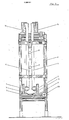
- Fig. 1 a device according to the invention, incorporating a supporting beam 1.
- a supporting beam 1 On this supporting beam 1 is on each side screwed (or fitted in another manner) a guide 2.
- Two mounting units 3 are displaceably arranged relative to each other upon these guides 2, which in turn are interconnected on the supporting beam 1.
- a shaft 4 extends through the mounting units 3.
- This shaft 4 consists of two units, which are connected by means of a sleeve 5.
- the shaft 4 is over a big range threaded from the connecting sleeve 5 and into the mounting units 3, on one side with left-handed and on the other side with right-handed threads. These threads cooperate with corresponding threads in the mounting units 3.
- the shaft 4 is axially arrested in a housing 6, which can also constitute a gear e.g. an angular gear.
- the mounting units 3 will move towards or away from each other, when the shaft 4 is rotated as they have opposed threads.
- the beams or legs 7 which shall support the conveyor tracks are fixedly mounted on the mounting units 3 and the mutual position between the conveyor tracks thus will be changed when the mounting units 3 are displaced towards or away from each other.
- the housing 6 is constituted by an angular gear or the like having a low gear change.
- the shaft 4 can be rotated via a gear in the housing 6 by means of a crank or the like but it is more convenient to provide an electromotor for this purpose.
- conveyor tracks that shall be supported by the device according to the invention are generally so long that they must be mounted in several spaced apart positions.
- connection shaft 8 projects from the housing 6, which shaft 8 is connected to an angular gear in a housing 6 in the following device and thereby drives the shaft 4 in this second device.
- a shaft 8 also may project from this device and drive the subsequent device, etcetera.
- a simultaneous adjustment of all supporting devices is in this manner obtained from a common driving source in accordance with the invention.
- FIG 2 is shown the same device as that in Figure 1 but seen from above.
- the beam 1 is provided with guides 2 and mounting units 3.
- On these mounting units 3 are intimated attachment points 9 for the legs 7, which shall support the conveyor tracks.
- Inside the mounting units 3 are fitted bushings 10 through which the guides 2 extend.
- the shaft 4 with threads extends through the nuts 11 fitted in the unit, which nuts have threads cooperating with the threads on the shaft 4.
- In the housing 6 is shown an angular gear which is driven via a shaft 12.
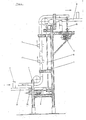
- Figures 3 and 4 show in a front view and a side view resp. conveyor tracks mounted by means of the device according to the invention.
- the mounting units 3 support the legs 7, which in turn support mounting clamps 13, which clamp around the conveyor tracks 14.
- the conveyor tracks are driven via drive shafts 15 from an electric motor 16.
- the objects 17 intended to be transported arrive to the conveyor tracks shown standing upon a conveyor track 18, and are seized by the conveyor tracks 14 and are delivered to the conveyor track 19.
- the mounting devices according to the invention are interconnected by means of a connecting shaft 8.
- a connecting shaft 8 By the present invention is thus obtained a very convenient and simple suspension of conveyor tracks of the type in question.
- the adjustment of the mutual relation between the tracks can be effected without stoppage and it can be made by unskilled personel. Fully automatic adjustment may also occur.
- the invention is not limited to the embodiment shown but can be varied in many different manners within the scope of the claims. It is thus possible that one of the mounting units 3 is disconnected from its threads, which means that only one of the conveyor tracks will move whereas the other one is stationary.
Landscapes
- Engineering & Computer Science (AREA)
- Mechanical Engineering (AREA)
- Chain Conveyers (AREA)
- Framework For Endless Conveyors (AREA)
- Structure Of Belt Conveyors (AREA)
Applications Claiming Priority (2)
| Application Number | Priority Date | Filing Date | Title |
|---|---|---|---|
| SE8701838A SE8701838L (sv) | 1987-05-05 | 1987-05-05 | Anordning foer fasthaallning av tvaa parallella banor |
| SE8701838 | 1987-05-05 |
Publications (2)
| Publication Number | Publication Date |
|---|---|
| EP0289811A2 true EP0289811A2 (de) | 1988-11-09 |
| EP0289811A3 EP0289811A3 (de) | 1989-03-15 |
Family
ID=20368412
Family Applications (1)
| Application Number | Title | Priority Date | Filing Date |
|---|---|---|---|
| EP88105705A Withdrawn EP0289811A3 (de) | 1987-05-05 | 1988-04-11 | Haltevorrichtung für zwei parallele Transportbalmen |
Country Status (4)
| Country | Link |
|---|---|
| US (1) | US4856643A (de) |
| EP (1) | EP0289811A3 (de) |
| JP (1) | JPS63282011A (de) |
| SE (1) | SE8701838L (de) |
Families Citing this family (5)
| Publication number | Priority date | Publication date | Assignee | Title |
|---|---|---|---|---|
| DE9100742U1 (de) * | 1991-01-23 | 1991-10-17 | VSR Engineering GmbH Fördertechnik, 4330 Mülheim | Schlauchgurtförderbandvorrichtung |
| US9171430B2 (en) * | 2013-08-06 | 2015-10-27 | Ncr Corporation | Media item transporter |
| US10745155B2 (en) * | 2013-09-05 | 2020-08-18 | Khs Gmbh | Retail-ready packaging of pouched product |
| US20170081129A1 (en) * | 2015-09-14 | 2017-03-23 | Industrial Dynamics Company Ltd | System and method for transporting containers in an inspection environment |
| CN108190739B (zh) * | 2018-01-18 | 2023-10-13 | 四川省公路规划勘察设计研究院有限公司 | 实验加载系统的试件变轨输送装置及吊装方法 |
Family Cites Families (4)
| Publication number | Priority date | Publication date | Assignee | Title |
|---|---|---|---|---|
| US1720680A (en) * | 1926-05-06 | 1929-07-16 | American Assembling Machine Co | Book-squeezing mechanism |
| US3858711A (en) * | 1972-09-12 | 1975-01-07 | Maynard C Barker | Conveying arrangement for containers |
| US4423745A (en) * | 1982-11-29 | 1984-01-03 | Simplimatic Engineering Company | Rinsing machine |
| US4694953A (en) * | 1985-06-12 | 1987-09-22 | Automation Service Equipment, Inc. | Drive for double gripper chain conveyor |
-
1987
- 1987-05-05 SE SE8701838A patent/SE8701838L/ not_active Application Discontinuation
-
1988
- 1988-04-11 EP EP88105705A patent/EP0289811A3/de not_active Withdrawn
- 1988-04-28 JP JP63104433A patent/JPS63282011A/ja active Pending
- 1988-05-04 US US07/189,991 patent/US4856643A/en not_active Expired - Lifetime
Also Published As
| Publication number | Publication date |
|---|---|
| SE8701838D0 (sv) | 1987-05-05 |
| US4856643A (en) | 1989-08-15 |
| EP0289811A3 (de) | 1989-03-15 |
| JPS63282011A (ja) | 1988-11-18 |
| SE8701838L (sv) | 1988-11-06 |
Similar Documents
| Publication | Publication Date | Title |
|---|---|---|
| US2951574A (en) | Path adjusting means for conveyors | |
| US5718323A (en) | Device for spacing products or product lots | |
| US4369872A (en) | Apparatus for the manufacture and/or handling of workpieces | |
| CN210022892U (zh) | 一种自适应抓取物流分拣系统 | |
| US4856643A (en) | Device for retaining two parallel tracks | |
| EP0982570A3 (de) | Automatische Waage für Obst und ähnliche | |
| SE464395B (sv) | Hanteringsutrustning | |
| US3236374A (en) | Line testing and handling apparatus | |
| CN119187045B (zh) | 一种物料分拣机构及物料分拣设备 | |
| US4854447A (en) | Belt conveyor system | |
| US4800640A (en) | Automated assembly system and method of assembly | |
| ATE93127T1 (de) | Foerderanlage fuer gegenstaende, wie insbesondere fruechte und gemuese, insbesondere zur qualitaetskontrolle. | |
| CA2090826A1 (fr) | Systeme de manipulation d'objets notamment pour machine de tri automatique de courrier | |
| JP2511996B2 (ja) | 基板移載装置 | |
| KR0133978B1 (ko) | 화면조정을 위한 제품위치결정장치 | |
| CN218537354U (zh) | 一种裹包机的放纸平台 | |
| CN220299643U (zh) | 一种植物油桶输送装置 | |
| CN219340656U (zh) | 高适应性的显示屏背板进料装置 | |
| JPH0676104B2 (ja) | キャップ締付け装置 | |
| CN221496953U (zh) | 一种对注塑件进行切水口、检测与分拣的设备 | |
| CN119871353B (zh) | 一种工业夹取机械手 | |
| SU863100A1 (ru) | Устройство дл отделени от пакета и подачи в зону обработки штучных длинномерных заготовок | |
| US6460686B1 (en) | Glass container inspection machine | |
| KR19980028736A (ko) | 석영관 자동 절단 장치 | |
| US20020081176A1 (en) | Glass container inspection machine |
Legal Events
| Date | Code | Title | Description |
|---|---|---|---|
| PUAI | Public reference made under article 153(3) epc to a published international application that has entered the european phase |
Free format text: ORIGINAL CODE: 0009012 |
|
| AK | Designated contracting states |
Kind code of ref document: A2 Designated state(s): DE ES FR GB IT |
|
| PUAL | Search report despatched |
Free format text: ORIGINAL CODE: 0009013 |
|
| AK | Designated contracting states |
Kind code of ref document: A3 Designated state(s): DE ES FR GB IT |
|
| 17P | Request for examination filed |
Effective date: 19890216 |
|
| 17Q | First examination report despatched |
Effective date: 19900423 |
|
| STAA | Information on the status of an ep patent application or granted ep patent |
Free format text: STATUS: THE APPLICATION IS DEEMED TO BE WITHDRAWN |
|
| 18D | Application deemed to be withdrawn |
Effective date: 19901019 |