EP0288433A1 - Kugelkäfig für einen Schraubantrieb - Google Patents
Kugelkäfig für einen Schraubantrieb Download PDFInfo
- Publication number
- EP0288433A1 EP0288433A1 EP88810219A EP88810219A EP0288433A1 EP 0288433 A1 EP0288433 A1 EP 0288433A1 EP 88810219 A EP88810219 A EP 88810219A EP 88810219 A EP88810219 A EP 88810219A EP 0288433 A1 EP0288433 A1 EP 0288433A1
- Authority
- EP
- European Patent Office
- Prior art keywords
- screw
- ball
- perforations
- groove
- cage
- Prior art date
- Legal status (The legal status is an assumption and is not a legal conclusion. Google has not performed a legal analysis and makes no representation as to the accuracy of the status listed.)
- Granted
Links
Images
Classifications
-
- F—MECHANICAL ENGINEERING; LIGHTING; HEATING; WEAPONS; BLASTING
- F16—ENGINEERING ELEMENTS AND UNITS; GENERAL MEASURES FOR PRODUCING AND MAINTAINING EFFECTIVE FUNCTIONING OF MACHINES OR INSTALLATIONS; THERMAL INSULATION IN GENERAL
- F16H—GEARING
- F16H25/00—Gearings comprising primarily only cams, cam-followers and screw-and-nut mechanisms
- F16H25/18—Gearings comprising primarily only cams, cam-followers and screw-and-nut mechanisms for conveying or interconverting oscillating or reciprocating motions
- F16H25/20—Screw mechanisms
- F16H25/22—Screw mechanisms with balls, rollers, or similar members between the co-operating parts; Elements essential to the use of such members
- F16H25/2204—Screw mechanisms with balls, rollers, or similar members between the co-operating parts; Elements essential to the use of such members with balls
- F16H25/2233—Screw mechanisms with balls, rollers, or similar members between the co-operating parts; Elements essential to the use of such members with balls with cages or means to hold the balls in position
-
- Y—GENERAL TAGGING OF NEW TECHNOLOGICAL DEVELOPMENTS; GENERAL TAGGING OF CROSS-SECTIONAL TECHNOLOGIES SPANNING OVER SEVERAL SECTIONS OF THE IPC; TECHNICAL SUBJECTS COVERED BY FORMER USPC CROSS-REFERENCE ART COLLECTIONS [XRACs] AND DIGESTS
- Y10—TECHNICAL SUBJECTS COVERED BY FORMER USPC
- Y10T—TECHNICAL SUBJECTS COVERED BY FORMER US CLASSIFICATION
- Y10T74/00—Machine element or mechanism
- Y10T74/19—Gearing
- Y10T74/19642—Directly cooperating gears
- Y10T74/19698—Spiral
- Y10T74/19702—Screw and nut
- Y10T74/19744—Rolling element engaging thread
- Y10T74/19781—Non-recirculating rolling elements
- Y10T74/19786—Captured sphere
Definitions
- the subject of the present invention is a ball nut cage made of synthetic material for a screw / nut type drive assembly, consisting of a cylindrical sleeve comprising ball housings constituted by cylindrical radial perforations, of substantially diameter equal to the diameter of the balls, distributed on at least one propeller corresponding to the groove, respectively to the helical grooves of the screw and intended to each receive a ball capable of freely rotating in its housing by cooperating with the groove, respectively the helical grooves of the screw to secure the nut and the screw.
- Such screw / nut assemblies are used for example for driving doors and gates.
- the balls are retained in their cage on the one hand by the screw and on the other hand by a cylindrical sleeve surrounding the ball cage, this sleeve being able to form an integral part of the element to be driven, for example a door or a gate.
- To install the balls in their housing it is essential that the ball cage is mounted on the screw.
- the balls tend to come out of their housing and to retain them, the time to mount the sleeve, it is customary to put grease in the housing. Despite this measure, it is not uncommon for logs to escape from their housing.
- the grease used for this purpose has a high viscosity which is not always compatible with the application.
- the screw / nut drive has to be dismantled, i.e. if it has to be removed the screw of the ball cage, the balls will escape from the cage, with the consequences that one can easily imagine. For the same reason, it is of course not possible to have in stock single ball cages provided with their balls.
- the object of the invention is to produce a ball cage in which the balls are retained without the aid of the screw or of an external sleeve.
- the ball cage according to the invention is characterized in that the internal surface of the cage has an excess thickness of material in the form of a cord extending along each helix on which perforations are arranged, on these perforations , and that the cylindrical surface of the perforations have, at its intersection with said bead, a narrowing and, at its outer end, asperities, so that the ball, once forced into its housing, is retained in its housing by this narrowing and these roughness.
- the ball cage is in all cases intended to be mounted in a sleeve or in a cylindrical hole, the roughness of the outer ends of the cylindrical perforations have no other force to bear than the weight of the balls during the implementation of these.
- Two or three small asperities are quite sufficient for this purpose and the low resistance which they offer to the insertion of the balls in the perforations can be overcome by a simple pressure of the finger.
- the internal narrowing of the perforations is preferably spherical in shape, with a radius close to that of the balls, but they could also be conical or pyramidal.
- the placement of the balls in the cage can be done in the absence of the screw, without grease and without special precautions. It can be easily automated. It is thus possible to have cages in stock fitted with their balls and ready to be mounted on a screw. During this mounting, the ends of the helical cords serve as a guide for the grooves of the screw, so that these grooves are immediately placed in front of the balls. The cords also prevent the rotation of the screw in the ball cage from having a cam effect capable of driving the balls out of their housing. Consequently, the ball cage can be mounted on the screw in the absence of an external sleeve. The disassembly of the screw / nut assembly can of course be done without risk of the balls escaping from the cage. In the case of an execution in synthetic material the cage according to the invention can be easily obtained by molding without additional machining.
- the section of the beads is preferably complementary to that of the grooves of the screw.
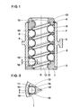
- the screw / nut assembly shown in the drawing comprises a ball cage 1 in the form of a cylindrical plastic sleeve housed in a cylindrical sleeve 2 in which it is retained at one end by a shoulder 3 and at the other end by a split ring 4 mounted in a groove of the cage 1.
- the sleeve 2 is part of an element not shown which could for example be a connecting piece to a portal.
- the cage 1 is provided with radial perforations such as 7 and 8 arranged along four angularly equidistant generatrices and each containing a ball such as 9 and 10 whose diameter is slightly less than the diameter of the cylindrical perforation and so that the balls can rotate freely in these perforations.
- the perforations are further distributed on a helix corresponding to the helical groove 11 of an endless screw 12 around which the ball cage is mounted 1.
- the groove 11 has a profile in an arc of a diameter corresponding to the diameter of the balls .
- Each ball can rotate freely in its housing formed by the perforation of the cage 1, the groove 11 of the screw and the inner wall of the sleeve 2.
- the internal surface of the cage 1 has a bead-shaped excess thickness 13 extending along the helix on which the perforations 7 and 8 are arranged, that is to say on a helix coinciding with the helical groove 11 of the screw 12.
- This cord 13 has a semicircular section of radius slightly smaller than the radii of the balls and of the section of the groove 11, and the center of which is therefore located on the axis of each perforation.
- the intersection of each perforation with the cord 13 has a narrowing 14 in the form of a spherical zone of radius substantially equal to the radius of the ball.
- each perforation located on the side of the sleeve 2 has four asperities 15, 16, 17 and 18 distributed around the periphery of the perforation.
- the dimensions of these protrusions are such that the balls can be introduced from the outside into the perforations by pressure by compressing the protrusions, the balls, once in their housing, being prevented from coming out by said protrusions.
- the plastic ball cage being obtained by injection molding, the radial orifices 7 and 8 are obtained by means of lateral movable rods whose ends are rounded so as to form the constrictions 14.
- the asperities 15 to 18 are formed by hollow provided on the rods. The small dimension of these roughnesses allows without other removal of the rods, during demolding, by elastic crushing of the roughness.
- the cords are obtained by means of a unscrewing spindle or a rotating tubular ejector.
- the balls are forced into the perforations of the cage 1, compressing the roughness 15 to 16. They abut against the narrowing 14, without it being necessary for the cage to be mounted on a worm.
- the finger pressure is sufficient.
- the introduction of the balls into their housing can be easily automated.
- the ball cage can then be stored with its balls without the balls may escape from the cage.
- the mounting of such a ball cage on a worm 12 can be done before or after mounting the ball cage in its sleeve 2.
- the helical cord 13 serves as a guide screw pitch for the introduction of the screw in the ball cage, so that the groove 11 of the screw is certainly in front of the balls.
- the cord 13 prevents the balls from being pushed out of their housing by a cam effect of the screw. There is therefore no risk of a ball escaping from its housing.
- the invention is of course susceptible of numerous variants.
- the number of rows of balls can be different from four.
- the balls will however preferably be distributed over at least three generators.
- the number of asperities 15 to 18 can be any.
- the socket may include several cords 13, in number equal to the number of helical grooves of the screw.
- the constriction 14, preferably of spherical shape, could have another shape, for example conical, the ball cage can be made of any material.
- the roughness 15 to 18 could be obtained by pushing the material from the edge of the perforation.
Priority Applications (1)
| Application Number | Priority Date | Filing Date | Title |
|---|---|---|---|
| AT88810219T ATE55456T1 (de) | 1987-04-21 | 1988-03-31 | Kugelkaefig fuer einen schraubantrieb. |
Applications Claiming Priority (2)
| Application Number | Priority Date | Filing Date | Title |
|---|---|---|---|
| FR8705593A FR2614381B1 (fr) | 1987-04-21 | 1987-04-21 | Cage a billes pour ensemble d'entrainement du type vis/ecrou |
| FR8705593 | 1987-04-21 |
Publications (2)
| Publication Number | Publication Date |
|---|---|
| EP0288433A1 true EP0288433A1 (de) | 1988-10-26 |
| EP0288433B1 EP0288433B1 (de) | 1990-08-08 |
Family
ID=9350312
Family Applications (1)
| Application Number | Title | Priority Date | Filing Date |
|---|---|---|---|
| EP88810219A Expired - Lifetime EP0288433B1 (de) | 1987-04-21 | 1988-03-31 | Kugelkäfig für einen Schraubantrieb |
Country Status (7)
| Country | Link |
|---|---|
| US (1) | US4821592A (de) |
| EP (1) | EP0288433B1 (de) |
| JP (1) | JPS63280954A (de) |
| AT (1) | ATE55456T1 (de) |
| DE (1) | DE3860412D1 (de) |
| ES (1) | ES2017800B3 (de) |
| FR (1) | FR2614381B1 (de) |
Families Citing this family (7)
| Publication number | Priority date | Publication date | Assignee | Title |
|---|---|---|---|---|
| JPH0456956U (de) * | 1990-09-25 | 1992-05-15 | ||
| US5241874A (en) * | 1990-11-27 | 1993-09-07 | Shunichi Matsuhama | Ball screw |
| JP3325679B2 (ja) * | 1993-12-10 | 2002-09-17 | 日本精工株式会社 | ボールねじのボール溝形状 |
| US5535638A (en) * | 1994-11-10 | 1996-07-16 | Cincinnati Milacron Inc. | Antifriction screw drive |
| DE19825769C2 (de) * | 1998-06-09 | 2003-04-17 | Franz Georg Miller | Kugelrollspindel |
| EP4095415A1 (de) * | 2021-05-24 | 2022-11-30 | Goodrich Actuation Systems Limited | Kugelgewindeanordnung |
| EP4145018A1 (de) | 2021-09-02 | 2023-03-08 | Goodrich Actuation Systems Limited | Leitspindelanordnung |
Citations (3)
| Publication number | Priority date | Publication date | Assignee | Title |
|---|---|---|---|---|
| US2069471A (en) * | 1936-06-19 | 1937-02-02 | Donald J Baker | Antifriction screw |
| US2350538A (en) * | 1942-11-16 | 1944-06-06 | Ex Cell O Corp | Lead control device |
| FR2536815A1 (fr) * | 1982-11-26 | 1984-06-01 | Micro Controle | Dispositif pour la transformation d'un mouvement de rotation en un mouvement de translation |
Family Cites Families (7)
| Publication number | Priority date | Publication date | Assignee | Title |
|---|---|---|---|---|
| US975591A (en) * | 1908-07-30 | 1910-11-15 | William A Whitney | Mechanical movement. |
| US1448426A (en) * | 1920-11-05 | 1923-03-13 | Oliver Chilled Plow Works | Screw device |
| US2768532A (en) * | 1952-09-13 | 1956-10-30 | Eaton Mfg Co | Power transmitting mechanism |
| US3003830A (en) * | 1955-11-08 | 1961-10-10 | Lempco Products Inc | Tubular-type antifriction bearing assemblies |
| GB1193466A (en) * | 1967-08-12 | 1970-06-03 | Rotolin Bearings Ltd | Guides for Die Sets |
| US4199999A (en) * | 1978-07-28 | 1980-04-29 | Norco, Inc. | Ball-type mechanical transmission |
| JPS55155921A (en) * | 1980-05-02 | 1980-12-04 | Ntn Toyo Bearing Co Ltd | Manufacture of slide bearing |
-
1987
- 1987-04-21 FR FR8705593A patent/FR2614381B1/fr not_active Expired
-
1988
- 1988-03-31 EP EP88810219A patent/EP0288433B1/de not_active Expired - Lifetime
- 1988-03-31 ES ES88810219T patent/ES2017800B3/es not_active Expired - Lifetime
- 1988-03-31 DE DE8888810219T patent/DE3860412D1/de not_active Expired - Lifetime
- 1988-03-31 AT AT88810219T patent/ATE55456T1/de not_active IP Right Cessation
- 1988-04-11 US US07/180,357 patent/US4821592A/en not_active Expired - Fee Related
- 1988-04-19 JP JP63096661A patent/JPS63280954A/ja active Pending
Patent Citations (3)
| Publication number | Priority date | Publication date | Assignee | Title |
|---|---|---|---|---|
| US2069471A (en) * | 1936-06-19 | 1937-02-02 | Donald J Baker | Antifriction screw |
| US2350538A (en) * | 1942-11-16 | 1944-06-06 | Ex Cell O Corp | Lead control device |
| FR2536815A1 (fr) * | 1982-11-26 | 1984-06-01 | Micro Controle | Dispositif pour la transformation d'un mouvement de rotation en un mouvement de translation |
Also Published As
| Publication number | Publication date |
|---|---|
| JPS63280954A (ja) | 1988-11-17 |
| DE3860412D1 (de) | 1990-09-13 |
| US4821592A (en) | 1989-04-18 |
| ATE55456T1 (de) | 1990-08-15 |
| ES2017800B3 (es) | 1991-03-01 |
| FR2614381A1 (fr) | 1988-10-28 |
| EP0288433B1 (de) | 1990-08-08 |
| FR2614381B1 (fr) | 1989-07-13 |
Similar Documents
| Publication | Publication Date | Title |
|---|---|---|
| EP0793024B1 (de) | Verbindungs- und Verriegelungsvorrichtung für teleskopische Rohre | |
| FR2510941A1 (fr) | Mandrin courbe pour vulcanisation d'un tuyau en polymere et procede d'utilisation | |
| FR2473151A1 (fr) | Dispositif de raccordement de tuyaux | |
| CH661110A5 (fr) | Structure demontable. | |
| EP0288433B1 (de) | Kugelkäfig für einen Schraubantrieb | |
| EP0584025B1 (de) | Spielfigur für Fussballspiel und ihre Befestigung auf einer Stützstange | |
| FR2468022A1 (fr) | Dispositif de raccordement demontable de tubes | |
| EP0263769A1 (de) | Tür- oder Fensterscharnier mit axialer Blockierung des Bolzens | |
| EP0228930A1 (de) | Verbindungsvorrichtung für Röhren oder Stäbe | |
| CH206498A (fr) | Roulement à éléments cylindriques. | |
| EP0084488A1 (de) | Radachse und Ansatzstück für deren Herstellung | |
| FR2757226A1 (fr) | Assemblage entre une vis de metal et une piece en matiere plastique | |
| EP1407169B1 (de) | Kugelumlaufspindelmutter | |
| FR2572008A1 (fr) | Perfectionnements aux assemblages a mi-bois | |
| EP0507712A1 (de) | Verbindungsvorrichtung für zwei schwenkende Schenkel eines Werkzeugs | |
| EP1106846A1 (de) | Vorrichtung zum reversiblen Blockieren einer Welle anhand von einem tangentialen Verriegelungsstift | |
| FR3084272A1 (fr) | Dispositif pour la tenue d'une tige comprenant un troncon filete | |
| FR2740184A1 (fr) | Procede de fixation d'un ecrou encage flottant sur une piece quelconque et assemblage obtenu par ce procede | |
| FR2720015A1 (fr) | Mandrin de cintrage pour tubes et analogues. | |
| FR2585590A1 (fr) | Rouleau a peindre | |
| EP2881528A1 (de) | Innengriff einer Tür oder eines Fensters | |
| FR2801942A1 (fr) | Ensemble forme d'un cylindre et d'une piece creuse | |
| FR2590332A1 (fr) | Dispositif d'assemblage pour tubes ou barres | |
| FR2526897A1 (fr) | Dispositif de montage de roulements | |
| BE485506A (de) |
Legal Events
| Date | Code | Title | Description |
|---|---|---|---|
| PUAI | Public reference made under article 153(3) epc to a published international application that has entered the european phase |
Free format text: ORIGINAL CODE: 0009012 |
|
| AK | Designated contracting states |
Kind code of ref document: A1 Designated state(s): AT BE CH DE ES GB IT LI NL SE |
|
| 17P | Request for examination filed |
Effective date: 19881208 |
|
| 17Q | First examination report despatched |
Effective date: 19890810 |
|
| GRAA | (expected) grant |
Free format text: ORIGINAL CODE: 0009210 |
|
| AK | Designated contracting states |
Kind code of ref document: B1 Designated state(s): AT BE CH DE ES GB IT LI NL SE |
|
| REF | Corresponds to: |
Ref document number: 55456 Country of ref document: AT Date of ref document: 19900815 Kind code of ref document: T |
|
| REF | Corresponds to: |
Ref document number: 3860412 Country of ref document: DE Date of ref document: 19900913 |
|
| ITF | It: translation for a ep patent filed |
Owner name: BUGNION S.P.A. |
|
| GBT | Gb: translation of ep patent filed (gb section 77(6)(a)/1977) | ||
| PLBE | No opposition filed within time limit |
Free format text: ORIGINAL CODE: 0009261 |
|
| STAA | Information on the status of an ep patent application or granted ep patent |
Free format text: STATUS: NO OPPOSITION FILED WITHIN TIME LIMIT |
|
| 26N | No opposition filed | ||
| PGFP | Annual fee paid to national office [announced via postgrant information from national office to epo] |
Ref country code: CH Payment date: 19920220 Year of fee payment: 5 |
|
| PGFP | Annual fee paid to national office [announced via postgrant information from national office to epo] |
Ref country code: AT Payment date: 19920311 Year of fee payment: 5 |
|
| PGFP | Annual fee paid to national office [announced via postgrant information from national office to epo] |
Ref country code: ES Payment date: 19920327 Year of fee payment: 5 |
|
| ITTA | It: last paid annual fee | ||
| PGFP | Annual fee paid to national office [announced via postgrant information from national office to epo] |
Ref country code: NL Payment date: 19920331 Year of fee payment: 5 |
|
| PGFP | Annual fee paid to national office [announced via postgrant information from national office to epo] |
Ref country code: BE Payment date: 19920512 Year of fee payment: 5 |
|
| PG25 | Lapsed in a contracting state [announced via postgrant information from national office to epo] |
Ref country code: LI Effective date: 19930331 Ref country code: CH Effective date: 19930331 Ref country code: BE Effective date: 19930331 Ref country code: AT Effective date: 19930331 |
|
| PG25 | Lapsed in a contracting state [announced via postgrant information from national office to epo] |
Ref country code: ES Free format text: LAPSE BECAUSE OF NON-PAYMENT OF DUE FEES Effective date: 19930401 |
|
| BERE | Be: lapsed |
Owner name: SOMFY Effective date: 19930331 |
|
| PG25 | Lapsed in a contracting state [announced via postgrant information from national office to epo] |
Ref country code: NL Effective date: 19931001 |
|
| NLV4 | Nl: lapsed or anulled due to non-payment of the annual fee | ||
| REG | Reference to a national code |
Ref country code: CH Ref legal event code: PL |
|
| PGFP | Annual fee paid to national office [announced via postgrant information from national office to epo] |
Ref country code: DE Payment date: 19940129 Year of fee payment: 7 |
|
| PGFP | Annual fee paid to national office [announced via postgrant information from national office to epo] |
Ref country code: SE Payment date: 19940316 Year of fee payment: 7 |
|
| PGFP | Annual fee paid to national office [announced via postgrant information from national office to epo] |
Ref country code: GB Payment date: 19940321 Year of fee payment: 7 |
|
| EAL | Se: european patent in force in sweden |
Ref document number: 88810219.1 |
|
| PG25 | Lapsed in a contracting state [announced via postgrant information from national office to epo] |
Ref country code: GB Effective date: 19950331 |
|
| PG25 | Lapsed in a contracting state [announced via postgrant information from national office to epo] |
Ref country code: SE Effective date: 19950401 |
|
| GBPC | Gb: european patent ceased through non-payment of renewal fee |
Effective date: 19950331 |
|
| PG25 | Lapsed in a contracting state [announced via postgrant information from national office to epo] |
Ref country code: DE Effective date: 19951201 |
|
| EUG | Se: european patent has lapsed |
Ref document number: 88810219.1 |
|
| REG | Reference to a national code |
Ref country code: ES Ref legal event code: FD2A Effective date: 19990301 |
|
| PG25 | Lapsed in a contracting state [announced via postgrant information from national office to epo] |
Ref country code: IT Free format text: LAPSE BECAUSE OF NON-PAYMENT OF DUE FEES;WARNING: LAPSES OF ITALIAN PATENTS WITH EFFECTIVE DATE BEFORE 2007 MAY HAVE OCCURRED AT ANY TIME BEFORE 2007. THE CORRECT EFFECTIVE DATE MAY BE DIFFERENT FROM THE ONE RECORDED. Effective date: 20050331 |