EP0287945A1 - Motor device comprising at least one coil, and process for manufacturing this coil - Google Patents
Motor device comprising at least one coil, and process for manufacturing this coil Download PDFInfo
- Publication number
- EP0287945A1 EP0287945A1 EP88105922A EP88105922A EP0287945A1 EP 0287945 A1 EP0287945 A1 EP 0287945A1 EP 88105922 A EP88105922 A EP 88105922A EP 88105922 A EP88105922 A EP 88105922A EP 0287945 A1 EP0287945 A1 EP 0287945A1
- Authority
- EP
- European Patent Office
- Prior art keywords
- coil
- rotor
- circuit
- coils
- stator
- Prior art date
- Legal status (The legal status is an assumption and is not a legal conclusion. Google has not performed a legal analysis and makes no representation as to the accuracy of the status listed.)
- Granted
Links
Images

Classifications
-
- H—ELECTRICITY
- H02—GENERATION; CONVERSION OR DISTRIBUTION OF ELECTRIC POWER
- H02K—DYNAMO-ELECTRIC MACHINES
- H02K37/00—Motors with rotor rotating step by step and without interrupter or commutator driven by the rotor, e.g. stepping motors
- H02K37/10—Motors with rotor rotating step by step and without interrupter or commutator driven by the rotor, e.g. stepping motors of permanent magnet type
- H02K37/12—Motors with rotor rotating step by step and without interrupter or commutator driven by the rotor, e.g. stepping motors of permanent magnet type with stationary armatures and rotating magnets
- H02K37/125—Magnet axially facing armature
-
- G—PHYSICS
- G04—HOROLOGY
- G04C—ELECTROMECHANICAL CLOCKS OR WATCHES
- G04C13/00—Driving mechanisms for clocks by master-clocks
- G04C13/08—Slave-clocks actuated intermittently
- G04C13/10—Slave-clocks actuated intermittently by electromechanical step advancing mechanisms
- G04C13/11—Slave-clocks actuated intermittently by electromechanical step advancing mechanisms with rotating armature
-
- H—ELECTRICITY
- H02—GENERATION; CONVERSION OR DISTRIBUTION OF ELECTRIC POWER
- H02K—DYNAMO-ELECTRIC MACHINES
- H02K3/00—Details of windings
- H02K3/04—Windings characterised by the conductor shape, form or construction, e.g. with bar conductors
- H02K3/26—Windings characterised by the conductor shape, form or construction, e.g. with bar conductors consisting of printed conductors
-
- H—ELECTRICITY
- H02—GENERATION; CONVERSION OR DISTRIBUTION OF ELECTRIC POWER
- H02K—DYNAMO-ELECTRIC MACHINES
- H02K99/00—Subject matter not provided for in other groups of this subclass
Definitions
- the MOS integrated circuit technology therefore makes it possible to produce, without additional manufacturing step, the module 24 grouping, on the same silicon wafer, the control circuit, the coils and the electrical connections of the coils to the circuit.
- These connections can be obtained either by metallization, when there is no intersection with another metallization, such as for example for conductor 34, or by means of a diffused conduction channel, of type p if the substrate is of type n, when there is a crossing, as is the case for the conductor 33 which must pass under the coil 26g.
Landscapes
- Engineering & Computer Science (AREA)
- Power Engineering (AREA)
- Physics & Mathematics (AREA)
- General Physics & Mathematics (AREA)
- Windings For Motors And Generators (AREA)
- Electromechanical Clocks (AREA)
- Iron Core Of Rotating Electric Machines (AREA)
- Reciprocating, Oscillating Or Vibrating Motors (AREA)
- Manufacture Of Motors, Generators (AREA)
Abstract
Description
La présente invention se rapporte au domaine des moteurs pas à pas miniatures comportant un stator, un rotor aimanté, et au moins une bobine couplée magnétiquement au rotor et reliée à un circuit de commande fournissant à la bobine les impulsions de courant nécessaires pour mettre en mouvement le rotor, le moteur associé au circuit de commande constituant un dispositif moteur.The present invention relates to the field of miniature stepping motors comprising a stator, a magnetic rotor, and at least one coil magnetically coupled to the rotor and connected to a control circuit supplying the coil with the current pulses necessary to set in motion. the rotor, the motor associated with the control circuit constituting a motor device.
L'invention concerne de tels dispositifs, particulièrement ceux utilisés dans les pièces d'horlogerie et notamment dans les montres.The invention relates to such devices, particularly those used in timepieces and in particular in watches.
Il est utile de rappeler que le moteur le plus utilisé actuellement dans les montres est un moteur pas à pas du type Lavet. Dans ce moteur un rotor aimanté de forme cylindrique crée un champ magnétique radial dans l'entrefer d'un circuit magnétique sur lequel est enroulée une bobine dont les bornes sont connectées à un circuit de commande, généralement un circuit intégré, fournissant des impulsions de courant, chaque impulsion faisant avancer le rotor d'un pas. La bobine est constituée par un fil très fin enroulé sur un tube isolant creux contenant à l'intérieur une partie du circuit magnétique. Le prix du fil, la difficulté de l'enrouler sur le tube et de réaliser des connexions fiables, font que la bobine constitue l'élément le plus coûteux du moteur.It is worth remembering that the most used motor currently in watches is a Lavet type stepper motor. In this motor, a cylindrical magnetized rotor creates a radial magnetic field in the air gap of a magnetic circuit on which is wound a coil whose terminals are connected to a control circuit, generally an integrated circuit, supplying current pulses. , each pulse advancing the rotor one step. The coil consists of a very fine wire wound on a hollow insulating tube containing inside a part of the magnetic circuit. The price of the wire, the difficulty of winding it on the tube and making reliable connections, make the coil the most expensive element of the motor.
Un autre type de moteur est quelquefois utilisé dans les montres. Dans ce cas le rotor a la forme d'un disque mince aimanté créant dans l'entrefer du circuit magnétique des champs axiaux qui traversent des bobines plates, c'est-à-dire sensiblement planes et de faible épaisseur, disposées parallèlement au rotor. Comme ce type de moteur utilise 6 à 8 bobines en fil de cuivre fin, délicates à réaliser et à connecter entre elles et au circuit de commande, il est encore plus cher à fabriquer que le moteur Lavet. Pour cette raison ce moteur, qui se prête pourtant bien à une construction compacte, n'est guère utilisé en horlogerie. Une réduction importante du prix des bobines a pu être obtenue en les réalisant simultanément sur un circuit imprimé, comme cela est décrit en détail dans le brevet US 4340833. Cette technique, intéressante pour les moteurs industriels, même de petite dimension, est cependant inapplicable au domaine horloger car elle ne permet pas de réaliser des bobines ayant des spires suffisamment fines pour assurer au moteur un bon rendement.Another type of motor is sometimes used in watches. In this case the rotor has the form of a thin magnetic disc creating in the air gap of the magnetic circuit axial fields which pass through flat coils, that is to say substantially flat and of small thickness, arranged parallel to the rotor. As this type of motor uses 6 to 8 coils of fine copper wire, which are difficult to produce and connect to each other and to the control circuit, it is even more expensive to manufacture than the Lavet motor. For this this engine, which lends itself well to a compact construction, is hardly used in watchmaking. A significant reduction in the price of the coils could be obtained by making them simultaneously on a printed circuit, as described in detail in US Pat. No. 4,340,833. This technique, which is advantageous for industrial motors, even of small size, is however not applicable to the horological field because it does not make it possible to produce coils having sufficiently fine turns to assure the motor a good performance.
Il apparaît clairement de ces exemples que les moteurs pas à pas actuellement utilisés dans les montres sont chers et manquent de fiabilité à cause, respectivement, du prix des bobines et de la difficulté de les relier au circuit de commande.It is clear from these examples that the stepping motors currently used in watches are expensive and unreliable due, respectively, to the price of the coils and the difficulty of connecting them to the control circuit.
La présente invention a pour but de pallier ces inconvénients en présentant un dispositif moteur comprenant:
- un stator;
- un rotor aimanté en forme de disque plan, monté pivotant dans le stator et comportant au moins une paire de pôles magnétiques produisant un champ sensiblement parallèle à l'axe de rotation du rotor dans un entrefer délimité par le stator et le rotor; et
- au moins une bobine sensiblement plane de faible épaisseur, cette bobine étant placée dans l'entrefer, perpendiculairement à l'axe de rotation, de manière à intercepter le flux créé par le champ,
qui est particulièrement remarquable en ce que la bobine est disposée sur une face d'une plaquette de semiconducteur dans laquelle est implanté un circuit de commande, ce circuit étant directement connecté à la bobine pour lui fournir des impulsions motrices.The aim of the present invention is to overcome these drawbacks by presenting a motor device comprising:
- a stator;
- a magnetized rotor in the form of a flat disc, pivotally mounted in the stator and comprising at least one pair of magnetic poles producing a field substantially parallel to the axis of rotation of the rotor in an air gap defined by the stator and the rotor; and
- at least one substantially flat coil of small thickness, this coil being placed in the air gap, perpendicular to the axis of rotation, so as to intercept the flow created by the field,
which is particularly remarkable in that the coil is arranged on one face of a semiconductor wafer in which a control circuit is implanted, this circuit being directly connected to the coil to supply it with driving pulses.
Le dispositif selon l'invention constitue une amélioration de l'ensemble que forment le moteur utilisant des bobines plates et le circuit de commande qui lui est associé.The device according to the invention constitutes an improvement of the assembly formed by the motor using flat coils and the control circuit associated with it.
Un avantage de l'invention résulte de ce que les bobines et le circuit de commande forment un module unique, de faible encombrement, pouvant être produit en grande série à un prix avantageux.An advantage of the invention results from the fact that the coils and the control circuit form a single module, of small bulk, which can be produced in large series at an advantageous price.
Un autre avantage provient du fait que le module simplifie le montage du dispositif tout en améliorant sa fiabilité. Encore un autre avantage est que le module permet de réduire les dimensions du dispositif moteur.Another advantage comes from the fact that the module simplifies the mounting of the device while improving its reliability. One again another advantage is that the module makes it possible to reduce the dimensions of the motor device.
D'autres caractéristiques et avantages du dispositif moteur selon l'invention ressortiront de la description qui va suivre, faite en regard du dessin annexé et donnant, à titre explicatif mais nullement limitatif, un exemple de réalisation d'un tel dispositif. Sur ce dessin, où les mêmes références se rapportent à des éléments analogues:
- - la figure 1a est une vue en coupe d'un moteur, connu de l'art antérieur, comportant un rotor aimanté en forme de disque mince et des bobines plates;
- - la figure 1b représente, dans une vue en plan, le rotor du moteur de la figure 1a montrant la disposition des pôles magnétiques;
- - la figure 1c représente, dans une vue en plan, les bobines du moteur de la figure 1a et les connexions de ces bobines à un circuit de commande;
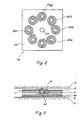
- - la figure 2 est une vue en plan d'un module selon l'invention formé d'une plaquette de silicium qui porte sur une face des bobines et dans laquelle est implanté un circuit intégré de commande dont la sortie est connectée aux bornes des bobines;
- - la figure 3 est une vue en plan d'une partie de la plaquette représentée sur la figure 2 montrant une bobine et sa liaison avec le circuit de commande; et
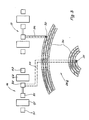
- - la figure 4 montre, dans une vue en coupe, un mode de réalisation avantageux du dispositif moteur selon l'invention, ce dispositif étant composé d'un moteur et d'un circuit de commande.
- - Figure 1a is a sectional view of a motor, known from the prior art, comprising a magnetic rotor in the form of a thin disc and flat coils;
- - Figure 1b shows, in a plan view, the rotor of the motor of Figure 1a showing the arrangement of the magnetic poles;
- - Figure 1c shows, in a plan view, the coils of the motor of Figure 1a and the connections of these coils to a control circuit;
- - Figure 2 is a plan view of a module according to the invention formed of a silicon wafer which bears on one face of the coils and in which is installed an integrated control circuit whose output is connected to the terminals of the coils ;
- - Figure 3 is a plan view of part of the wafer shown in Figure 2 showing a coil and its connection to the control circuit; and
- - Figure 4 shows, in a sectional view, an advantageous embodiment of the motor device according to the invention, this device being composed of a motor and a control circuit.
Un moteur, connu de l'art antérieur et comportant des bobines plates, est représenté en coupe sur la figure 1a. Ce moteur comprend un rotor 1, un stator 2, et un arbre 3 solidaire du rotor et pivotant dans le stator. Le stator peut avantageusement être constitué, dans le cas d'un moteur de montre, par des éléments de la platine du mouvement. Le rotor est composé, de son côté, d'un disque circulaire aimanté 4, disposé près d'une des extrémités de l'arbre 3, et d'une première plaque circulaire 5 en matériau magnétique doux, cette plaque étant fixée sur la face du disque 4 la plus proche du stator 2. Le moteur comprend en outre, disposées sur le stator 2, une deuxième plaque circulaire 6, de même forme que la plaque 5, une feuille isolante 7, et 8 bobines plates 8a, 8b... 8h. La plaque 6 est fixée sur la partie du stator se trouvant en regard de la face libre du disque en ferrite 4, l'espace entre la plaque 6 et le rotor 1 définissant un entrefer. Enfin les bobines, référencées 8a, 8b... 8h, sont disposées dans l'entrefer sur la plaque 6, la feuille 7 étant interposée entre la plaque 6 et les bobines pour assurer leur isolation.A motor, known from the prior art and comprising flat coils, is shown in section in FIG. 1a. This motor comprises a
La figure 1b montre, dans une vue en plan, le disque 4 et la disposition des pôles magnétiques, le disque pouvant avantageusement être réalisé en ferrite ou en samarium-cobalt. Dans l'exemple représenté, le disque 4 comporte 4 paires de pôles magnétiques disposés au voisinage de la périphérie du rotor. Ces pôles créent des champs magnétiques H dans l'entrefer séparant le rotor 1 du stator 2, à l'endroit où se trouvent les bobines 8a... 8h. Dans l'entrefer, les champs H ont tous sensiblement la même direction, parallèle à l'axe de rotation du rotor, mais leur sens est alterné. En dehors de l'entrefer, les champs sont canalisés d'un pôle magnétique au pôle adjacent par les plaques 5 et 6 qui présentent, à cet effet, une perméabilité magnétique élevée. Si la partie du stator 2 se trouvant au voisinage de bobines était réalisée en un matériau magnétique doux, la plaque 6 serait bien entendu inutile.Figure 1b shows, in a plan view, the
La forme et la disposition des bobines 8a ... 8h sont représentées en plan sur la figure 1c. Ces bobines, semblables les unes aux autres, se présentant sous la forme de disques circulaires plans ayant une épaisseur faible par rapport à leur diamètre extérieur, sont disposées de manière à intercepter le maximum du flux créé par les champs magnétiques H dans l'entrefer. Chaque bobine, réalisée avec du fil de cuivre très mince, comporte une borne d'entrée et une borne de sorties, ces bornes étant référencées respectivement 9a et 10a pour la bobine 8a, 9b et 10b pour la bobine 8b, etc. Enfin, dans l'exemple représenté, d'une part, les spires d'une bobine sont enroulées dans un sens et les spires d'une bobine adjacente dans le sens inverse et, d'autre part, toutes les bornes d'entrée des bobines sont reliées ensemble par un conducteur 11, et toutes les bornes de sortie par un conducteur 12. Dans ces conditions, des courants de même sens circulent dans les parties voisines des spires de deux bobines adjacentes en réponse à une tension appliquée entre les conducteurs 11 et 12.The shape and arrangement of the
Sur la figure 1c est encore représenté un circuit de commande 15. Ce circuit, réalisé généralement sous la forme d'un circuit intégré implanté dans une plaquette de silicium, est destiné à fournir aux bobines des impulsions motrices de courant pour faire tourner le rotor. Le circuit 15 comprend deux inverseurs, référencés 16 et 17, et un circuit logique 18. Les sorties des inverseurs sont connectées respectivement aux conducteurs 11 et 12, par des fils référencés 19 et 20, alors que les entrées de ces inverseurs sont reliées directement au circuit 18.In FIG. 1c, a
Si le dispositif moteur est destiné à équiper une montre, le circuit 18 comprend essentiellement un circuit base de temps stabilisé en fréquence par un résonateur à quartz, un diviseur de fréquence, et un circuit de mise en forme des signaux attaquant les inverseurs 16 et 17, ces inverseurs fournissant alors aux bobines du moteur des impulsions motrices polarisées. Le circuit 18 comporte encore au moins une borne d'entrée permettant de mettre la montre à l'heure au moyen de signaux fournis par au moins un organe de commande extérieur. Le circuit 15 est enfin alimenté en énergie par une pile disposée à l'intérieur de la boîte de montre. Ces parties de circuit et ces composants, étant connus en soi, ne sont pas représentés sur la figure 1c et ils ne seront pas décrits non plus.If the motor device is intended to equip a watch, the
Le dispositif moteur qui vient d'être décrit peut se présenter sous des formes légèrement différentes mais connues. En particulier il y a intérêt, pour augmenter la longueur de la partie active des spires et améliorer le rendement du moteur, à donner aux bobines 8a ... 8h une forme triangulaire, semblable à celle représentée sur la figure 5 du document cité. D'autre part les bobines, au lieu d'être reliées en parallèle, pourraient être connectées en série. Enfin chaque bobine pourrait aussi être reliée directement à une paire d'inverseurs, le circuit 15 comportant alors autant de paires d'inverseurs, semblables aux inverseurs 16 et 17, qu'il y a de bobines.The motor device which has just been described can be in slightly different but known forms. In particular, it is advantageous, to increase the length of the active part of the turns and improve the efficiency of the motor, to give the
La présente invention se propose, lorsque le circuit de commande 15 est un circuit intégré, de simplifier et de rendre plus fiable un tel dispositif moteur en regroupant, en un module unique, le circuit, les bobines et les connexions entre le circuit et les bobines.The present invention proposes, when the
Un tel module, référencé 24, est représenté en plan sur la figure 2. Il comprend une plaquette de silicium 25, appelée aussi substrat semiconducteur, un circuit intégré de commande non représenté, réalisé selon la technologie CMOS et implanté dans le substrat, et huit bobines, références 26a, 26b, ... 26g, 26h, disposées sur une face de la plaquette au centre de laquelle est pratiqué un trou 27 pour laisser passer l'arbre 3 du rotor. Les bobines 26a... 26h, directement connectées au circuit de commande, ont la même fonction que les bobines 8a.... 8h précédemment décrites.Such a module, referenced 24, is shown in plan in Figure 2. It comprises a
Dans le cas d'un dispositif moteur pour montre, la plaquette 25 est de forme carrée et mesure typiquement 4 mm de côté et 0,2 mm d'épaisseur, alors que les bobines 26a... 26h ont un diamètre extérieur d'environ 1 mm et une épaisseur négligeable. Dans ces conditions, le diamètre du rotor 1 est d'environ 5 mm. D'autre part, le disque 4 et les plaques 5 et 6 ont respectivement environ 0,4 mm et 0,3 mm d'épaisseur. La hauteur totale du moteur, en admettant qu'il existe un espace de 0,1 mm entre le disque 4 et les bobines 26a... 26h, devient alors égale à 1,3 mm.In the case of a watch motor device, the
Une partie de la plaquette 25 est représentée dans une vue en plan agrandie sur la figure 3, montrant la bobine 26g, les deux inverseurs 16 et 17 du circuit intégré de commande 15, et les connexions entre les extrémités de la bobine et les sorties des inverseurs.Part of the
La bobine 26g comprend environ 150 spires. Elle est formée par un conducteur 30 en aluminium, enroulé en spirale sur une seule couche, la distance entre deux spires étant de l'ordre du micromètre. Le conducteur 30, qui présente une borne intérieure 31 et une borne extérieure 32, a une section carrée de 2 micromètres de côté et une résistance entre ces bornes, correspondant à la résistance de la bobine, de l'ordre de 2'000 ohms. La bobine 26g a, dans l'exemple représenté, une forme circulaire mais, bien entendu, sa forme pourrait être triangulaire afin d'améliorer le rendement du moteur.The 26g coil includes around 150 turns. It is formed by an
L'inverseur 16, représenté sur la figure 3, est formé de deux transistors complémentaires CMOS, chaque transistor comportant une source, une grille et un drain, notés respectivement S₁, G₁, et D₁ pour le premier transistor et S₂, G₂ et D₂ pour le deuxième. Les drains D₁ et D₂ sont reliés ensemble et ils forment la sortie de l'inverseur 16. Cette sortie est connectée à la borne 31 par un conducteur électrique 33. L'inverseur 17 a une structure identique à celle de l'inverseur 16 et sa sortie est reliée à la borne 32 par un conducteur électrique 34. Les autres bobines peuvent être connectées en parallèle sur la bobine 26g.The
Cependant, afin de diminuer la longueur des conducteurs de liaison, il y a intérêt à relier chaque bobine directement à une paire d'inverseurs identiques aux inverseurs 16 et 17. Le reste du circuit de commande et des connexions n'a pas été représenté. Comme ces éléments occupent une place relativement restreinte, ils peuvent être implantés, par exemple, dans un des coins de la plaquette 25.However, in order to reduce the length of the connecting conductors, it is advantageous to connect each coil directly to a pair of inverters identical to the
Les bobines 26a... 26h peuvent avantageusement être réalisées sur la plaquette de silicium 25 par le même procédé, et en même temps, que celui qui permet de fabriquer dans cette plaquette le circuit intégré de commande, et cela sans nécessiter d étape de fabrication supplémentaire.The
Pour comprendre comment les bobines peuvent être obtenues, il faut rappeler auparavant que la fabrication d'un circuit intégré MOS comporte plusieurs étapes, les plus importantes consistant:
- à diffuser dans la plaquette de silicium à travers des masques successifs des impuretés en des endroits bien définis pour constituer les différents composants actifs et passifs du circuit,
- à recouvrir la surface du circuit par une couche isolante d'oxyde de silicium;
- à pratiquer dans la couche d'oxyde des ouvertures aux endroits où le circuit présente des bornes de connexion; enfin
- à déposer à travers un masque de métallisation, par un processus de métallisation sous vide, des pistes conductrices en aluminium reliant sélectivement entre elles les bornes de connexion.To understand how the coils can be obtained, it must first be remembered that the manufacturing of an MOS integrated circuit involves several steps, the most important of which are:
- to diffuse in the silicon wafer through successive masks impurities in well defined places to constitute the various active and passive components of the circuit,
- to cover the surface of the circuit with an insulating layer of silicon oxide;
- to make openings in the oxide layer where the circuit has connection terminals; finally
- to deposit through a metallization mask, by a vacuum metallization process, conductive aluminum tracks selectively connecting the connection terminals to each other.
Si le masque de métallisation comporte en outre le dessin des spires des bobines et celui de leurs liaisons avec le circuit, il est évident que les bobines et les connexions entre les bobines et le circuit seront obtenues en même temps, et par le même processus, que les autres métallisations. La finesse de définition des conducteurs que permet le processus de métallisation est par ailleurs compatible avec les faibles dimensions des bobines et des conducteurs formant les spires, indiquées plus haut, nécessaires pour obtenir un bon rendement du moteur.If the metallization mask also includes the drawing of the turns of the coils and that of their connections with the circuit, it is obvious that the coils and the connections between the coils and the circuit will be obtained at the same time, and by the same process, than other metallizations. The fineness of definition of the conductors that the metallization process allows is also compatible with the small dimensions of the coils and of the conductors forming the turns, indicated above, necessary to obtain a good efficiency of the motor.
La technologie des circuits intégrés MOS permet donc de réaliser, sans étape de fabrication supplémentaire, le module 24 regroupant, sur la même plaquette de silicium, le circuit de commande, les bobines et les liaisons électriques des bobines au circuit. Ces liaisons peuvent être obtenues soit par une métallisation, lorsqu'il n'y a pas de croisement avec une autre métallisation, comme par exemple pour le conducteur 34, soit au moyen d'un canal de conduction diffusé, du type p si le substrat est du type n, lorsqu'il y a croisement, comme c'est le cas pour le conducteur 33 qui doit passer sous la bobine 26g.The MOS integrated circuit technology therefore makes it possible to produce, without additional manufacturing step, the
Ce module permet de simplifier la construction du dispositif moteur en diminuant le nombre des composants. Une réalisation avantageuse est représentée sur la figure 4 où les références 1, 2, 4, 5 et 6 désignent les mêmes éléments que ceux de la figure 1a, à savoir, respectivement, le rotor, le stator, le disque de ferrite, et les deux plaques en matériau magnétique doux. Le module, référencé 24, est fixé directement sur la plaque 6, à la place des bobines 8a... 8h de la figure 1a, de manière que sa face portant les bobines 26a... 26h se trouve en regard du rotor. En son centre, le module supporte un tenon circulaire 40 qui, en venant s'engager dans un palier 41 fixé au centre du rotor 1, sert à ce dernier d'arbre de rotation. Avec cette disposition le module 24 n'a pas besoin d'être percé en son centre, opération délicate qui était rendue nécessaire dans la réalisation représentée sur la figure 1a pour laisser passer l'arbre 3.This module simplifies the construction of the motor device by reducing the number of components. An advantageous embodiment is shown in FIG. 4 where the
Il est bien entendu que le dispositif moteur qui vient d'être décrit peut subir encore d'autres modifications et se présenter sous différentes variantes évidentes à l'homme du métier, sans sortir du cadre de la présente invention.It is understood that the motor device which has just been described can undergo further modifications and come in different variants obvious to those skilled in the art, without departing from the scope of the present invention.
Claims (6)
- un stator (2);
- un rotor (1) aimanté en forme de disque plan, monté pivotant dans le stator et comportant au moins une paire de pôles magnétiques produisant un champ (H) sensiblement parallèle à l'axe de rotation du rotor dans un entrefer délimité par le stator et le rotor; et
- au moins une bobine (26a) sensiblement plane, ladite bobine étant placée dans l'entrefer, perpendiculairement à l'axe de rotation, de manière à intercepter le flux créé par le champ,
caractérisé en ce que ladite bobine (26a) est disposée sur une face d'une plaquette (25) de semiconducteur dans laquelle est implanté un circuit intégré de commande, ledit circuit étant directement connecté à la bobine pour lui fournir des impulsions motrices.1. Motor device comprising:
- a stator (2);
- a rotor (1) magnetized in the form of a flat disc, pivotally mounted in the stator and comprising at least one pair of magnetic poles producing a field (H) substantially parallel to the axis of rotation of the rotor in an air gap defined by the stator and the rotor; and
- at least one substantially flat coil (26a), said coil being placed in the air gap, perpendicular to the axis of rotation, so as to intercept the flow created by the field,
characterized in that said coil (26a) is arranged on one face of a semiconductor wafer (25) in which an integrated control circuit is installed, said circuit being directly connected to the coil to supply it with driving pulses.
Applications Claiming Priority (2)
| Application Number | Priority Date | Filing Date | Title |
|---|---|---|---|
| CH1549/87 | 1987-04-22 | ||
| CH154987A CH668160GA3 (en) | 1987-04-22 | 1987-04-22 |
Publications (2)
| Publication Number | Publication Date |
|---|---|
| EP0287945A1 true EP0287945A1 (en) | 1988-10-26 |
| EP0287945B1 EP0287945B1 (en) | 1991-07-24 |
Family
ID=4213007
Family Applications (1)
| Application Number | Title | Priority Date | Filing Date |
|---|---|---|---|
| EP88105922A Expired - Lifetime EP0287945B1 (en) | 1987-04-22 | 1988-04-14 | Motor device comprising at least one coil, and process for manufacturing this coil |
Country Status (6)
| Country | Link |
|---|---|
| US (1) | US5039895A (en) |
| EP (1) | EP0287945B1 (en) |
| JP (1) | JP2647425B2 (en) |
| CH (1) | CH668160GA3 (en) |
| DE (1) | DE3863826D1 (en) |
| HK (1) | HK142394A (en) |
Cited By (5)
| Publication number | Priority date | Publication date | Assignee | Title |
|---|---|---|---|---|
| EP0444539A1 (en) * | 1990-03-02 | 1991-09-04 | Eta SA Fabriques d'Ebauches | Exciting coil set, method of fabricating the same and micromotor equipped therewith |
| EP0520631A2 (en) * | 1991-06-24 | 1992-12-30 | Wisconsin Alumni Research Foundation | Micromechanical magnetic devices and method of producing the same |
| EP0619642A2 (en) * | 1993-04-05 | 1994-10-12 | Ford Motor Company Limited | Micro-motor and method of fabrication |
| US7049025B2 (en) | 2000-11-07 | 2006-05-23 | Johnson Matthey Public Limited Company | Gas diffusion substrate |
| EP3255763A1 (en) * | 2016-06-10 | 2017-12-13 | Richemont International S.A. | Microgenerator for a timepiece and manufacturing method of a microgenerator for a timepiece |
Families Citing this family (14)
| Publication number | Priority date | Publication date | Assignee | Title |
|---|---|---|---|---|
| US5184040A (en) * | 1989-09-04 | 1993-02-02 | Lim Jong H | Electric power generators having like numbers of magnets and coils |
| DE4012546A1 (en) * | 1990-04-19 | 1991-10-24 | Siemens Ag | TURN DETECTOR |
| JPH0779582A (en) * | 1993-09-09 | 1995-03-20 | Toshiba Corp | Optically driven motor |
| US5686769A (en) * | 1995-05-26 | 1997-11-11 | Eastman Kodak Company | Method of coil mounting for maximum heat transfer in brushless DC motors |
| GB9510994D0 (en) * | 1995-05-31 | 1995-07-26 | Turbo Genset The Company Ltd | Rotary electrical machines |
| US6169354B1 (en) * | 1996-05-24 | 2001-01-02 | Halo Data Devices, Inc. | Thin film electric motors |
| US6204588B1 (en) | 1999-05-27 | 2001-03-20 | Halo Data Devices, Inc. | Rotor capable of being used as a recording media |
| ATE424575T1 (en) * | 1999-11-12 | 2009-03-15 | Asulab Sa | GENERATOR FOR TIMER |
| US20020170163A1 (en) * | 2000-11-27 | 2002-11-21 | Jeewan Puri | Dished disk windings for cast winding applications |
| US6822369B2 (en) * | 2001-07-27 | 2004-11-23 | Ta-Ching Pong | Pulse propelling flat induction motor |
| JP3621696B2 (en) * | 2002-08-14 | 2005-02-16 | 株式会社東芝 | Hall element, motor assembly, and optical disc apparatus |
| DE102010045536B4 (en) * | 2010-09-15 | 2012-06-21 | Trw Automotive Electronics & Components Gmbh | Electrodynamic actuator |
| US10128789B2 (en) * | 2014-10-10 | 2018-11-13 | The Boeing Company | Phantom electric motor system with parallel coils |
| EP4142125A1 (en) * | 2021-08-26 | 2023-03-01 | Universidad de Alcalá (UAH) | Miniaturized electromagnetic rotary actuator |
Citations (1)
| Publication number | Priority date | Publication date | Assignee | Title |
|---|---|---|---|---|
| FR2146527A5 (en) * | 1971-07-16 | 1973-03-02 | Amouriq Paul |
Family Cites Families (13)
| Publication number | Priority date | Publication date | Assignee | Title |
|---|---|---|---|---|
| JPS5927988B2 (en) * | 1974-06-14 | 1984-07-10 | 株式会社東芝 | turntable device |
| GB2072891B (en) * | 1977-06-20 | 1982-08-25 | Hitachi Ltd | Electronic device and method of fabricating the same |
| JPS5678342A (en) * | 1979-11-26 | 1981-06-27 | Kangiyou Denki Kiki Kk | Printed circuit |
| JPS5690551A (en) * | 1979-12-24 | 1981-07-22 | Mitsubishi Electric Corp | Inductor device for integrated circuit |
| JPS56139066A (en) * | 1980-03-31 | 1981-10-30 | Matsushita Electric Works Ltd | Step motor |
| JPS60156253A (en) * | 1984-01-24 | 1985-08-16 | Takahashi Yoshiteru | Disc type brushless motor with one position detector two armature coils for flowing one phase |
| JPS60200754A (en) * | 1984-03-21 | 1985-10-11 | Sankyo Seiki Mfg Co Ltd | Drive motor |
| JPS60225449A (en) * | 1984-04-24 | 1985-11-09 | Sumitomo Electric Ind Ltd | Semiconductor ic package |
| JP2567219B2 (en) * | 1985-07-03 | 1996-12-25 | 日本エルエスアイカード 株式会社 | Non-contact method for writing / reading between memory substrate and read / write device |
| JPS62165393A (en) * | 1986-01-16 | 1987-07-21 | 三洋電機株式会社 | Hybrid integrated circuit substrate |
| JPS62201047A (en) * | 1986-02-28 | 1987-09-04 | Toshiba Corp | Brushless motor |
| US4801830A (en) * | 1986-08-04 | 1989-01-31 | Canon Kabushiki Kaisha | Brushless motor |
| US4733115A (en) * | 1986-12-16 | 1988-03-22 | Eastman Kodak Company | Electric motor |
-
1987
- 1987-04-22 CH CH154987A patent/CH668160GA3/fr not_active IP Right Cessation
-
1988
- 1988-04-11 US US07/180,348 patent/US5039895A/en not_active Expired - Lifetime
- 1988-04-14 EP EP88105922A patent/EP0287945B1/en not_active Expired - Lifetime
- 1988-04-14 DE DE8888105922T patent/DE3863826D1/en not_active Expired - Lifetime
- 1988-04-21 JP JP63096982A patent/JP2647425B2/en not_active Expired - Lifetime
-
1994
- 1994-12-15 HK HK142394A patent/HK142394A/en not_active IP Right Cessation
Patent Citations (1)
| Publication number | Priority date | Publication date | Assignee | Title |
|---|---|---|---|---|
| FR2146527A5 (en) * | 1971-07-16 | 1973-03-02 | Amouriq Paul |
Non-Patent Citations (4)
| Title |
|---|
| PATENT ABSTRACTS OF JAPAN, vol. 10, no. 79 (E-391)[2136], 28 mars 1986; & JP-A-60 225 449 (SUMITOMO DENKI KOGYO K.K.) 09-11-1985 * |
| PATENT ABSTRACTS OF JAPAN, vol. 5, no. 159 (E-77)[831], 14 octobre 1981; & JP-A-56 090 551 (MITSUBISHI DENKI K.K.) 22-07-1981 * |
| PATENT ABSTRACTS OF JAPAN, vol. 6, no. 21 (E-93)[899], 6 février 1982; & JP-A-56 139 066 (MATSUSHITA DENKO K.K.) 30-10-1981 * |
| PATENT ABSTRACTS OF JAPAN, vol. 9, no. 325 (E-368)[2048], 20 décembre 1985; & JP-A-60 156 253 (YOSHITERU TAKAHASHI) 16-08-1985 * |
Cited By (10)
| Publication number | Priority date | Publication date | Assignee | Title |
|---|---|---|---|---|
| EP0444539A1 (en) * | 1990-03-02 | 1991-09-04 | Eta SA Fabriques d'Ebauches | Exciting coil set, method of fabricating the same and micromotor equipped therewith |
| FR2659178A1 (en) * | 1990-03-02 | 1991-09-06 | Ebauchesfabrik Eta Ag | EXCITATION COIL ASSEMBLY, METHOD FOR MANUFACTURING SUCH ASSEMBLY, AND ELECTROMAGNETIC MICROMOTOR EQUIPPED WITH THE SAME |
| US5113100A (en) * | 1990-03-02 | 1992-05-12 | Eta Sa Fabriques D'ebauches | Energization coil device, a method of making such a device and an electromagnetic micromotor fitted therewith |
| EP0520631A2 (en) * | 1991-06-24 | 1992-12-30 | Wisconsin Alumni Research Foundation | Micromechanical magnetic devices and method of producing the same |
| EP0520631A3 (en) * | 1991-06-24 | 1993-03-03 | Wisconsin Alumni Research Foundation | Micromechanical magnetic devices and method of producing the same |
| US5327033A (en) * | 1991-06-24 | 1994-07-05 | Wisconsin Alumni Research Foundation | Micromechanical magnetic devices |
| EP0619642A2 (en) * | 1993-04-05 | 1994-10-12 | Ford Motor Company Limited | Micro-motor and method of fabrication |
| EP0619642A3 (en) * | 1993-04-05 | 1994-11-17 | Ford Motor Co | Micro-motor and method of fabrication. |
| US7049025B2 (en) | 2000-11-07 | 2006-05-23 | Johnson Matthey Public Limited Company | Gas diffusion substrate |
| EP3255763A1 (en) * | 2016-06-10 | 2017-12-13 | Richemont International S.A. | Microgenerator for a timepiece and manufacturing method of a microgenerator for a timepiece |
Also Published As
| Publication number | Publication date |
|---|---|
| DE3863826D1 (en) | 1991-08-29 |
| JPS63283459A (en) | 1988-11-21 |
| HK142394A (en) | 1994-12-23 |
| CH668160GA3 (en) | 1988-12-15 |
| EP0287945B1 (en) | 1991-07-24 |
| US5039895A (en) | 1991-08-13 |
| JP2647425B2 (en) | 1997-08-27 |
Similar Documents
| Publication | Publication Date | Title |
|---|---|---|
| EP0287945B1 (en) | Motor device comprising at least one coil, and process for manufacturing this coil | |
| EP0444539B1 (en) | Exciting coil set, method of fabricating the same and micromotor equipped therewith | |
| EP0869519B1 (en) | Planar magnetic motor and magnetic microactuator with such a motor | |
| FR2695787A1 (en) | Built-in capacitive transducer. | |
| EP1031844A2 (en) | Process for forming an electrical current sensor | |
| EP0466874A1 (en) | Electrostatic radial field micromotor obtained by photolithographic micromanufacture and method of manufacture thereof | |
| EP0509351B1 (en) | Electromagnetic motor having two rotation directions, in particular for timepiece | |
| EP1286465A1 (en) | Microelectromechanical device | |
| FR2461392A1 (en) | TWO-WAY ELECTROMAGNETIC MOTOR | |
| EP2169479B1 (en) | Time base device for a watch | |
| EP0613594A1 (en) | Elongate torque motor and angular displacement control device incorporating it. | |
| EP0392944B1 (en) | High voltage spiral resistor | |
| EP0034102B1 (en) | Integrated voltage multiplier | |
| EP0547534B1 (en) | Electromagnetic transducer with a multipolar permanent magnet | |
| EP0174322B1 (en) | Multipolar magnetization device | |
| EP0240435A1 (en) | Resistor integrated on a semiconductor substrate | |
| EP1890204B1 (en) | Electronic timepiece comprising a resonator | |
| EP0132633B1 (en) | Electromagnetic stepping motor | |
| EP0782242B1 (en) | Multi-rotor electromechanical transducer and control method thereof | |
| FR2705827A1 (en) | Improvements to the devices for manufacturing the electrets and to the electrets obtained. | |
| EP0039649B1 (en) | Electric direct current motor | |
| FR2803131A1 (en) | Small electric motor e.g. for toys, has portion of outer case acting as one of electrode terminals | |
| FR2488765A1 (en) | Electrodynamic transducer usable as loudspeaker or microphone - has coil formed as printed circuit group of spirals on both faces of membrane above alternating concentric magnetic poles | |
| EP1121748B1 (en) | Rotary magnetic actuator | |
| CH600660A (en) | Small stepping motor for wrist watches |
Legal Events
| Date | Code | Title | Description |
|---|---|---|---|
| PUAI | Public reference made under article 153(3) epc to a published international application that has entered the european phase |
Free format text: ORIGINAL CODE: 0009012 |
|
| AK | Designated contracting states |
Kind code of ref document: A1 Designated state(s): DE FR GB |
|
| 17P | Request for examination filed |
Effective date: 19890210 |
|
| 17Q | First examination report despatched |
Effective date: 19901227 |
|
| GRAA | (expected) grant |
Free format text: ORIGINAL CODE: 0009210 |
|
| AK | Designated contracting states |
Kind code of ref document: B1 Designated state(s): DE FR GB |
|
| REF | Corresponds to: |
Ref document number: 3863826 Country of ref document: DE Date of ref document: 19910829 |
|
| GBT | Gb: translation of ep patent filed (gb section 77(6)(a)/1977) | ||
| PLBE | No opposition filed within time limit |
Free format text: ORIGINAL CODE: 0009261 |
|
| STAA | Information on the status of an ep patent application or granted ep patent |
Free format text: STATUS: NO OPPOSITION FILED WITHIN TIME LIMIT |
|
| 26N | No opposition filed | ||
| REG | Reference to a national code |
Ref country code: GB Ref legal event code: IF02 |
|
| PGFP | Annual fee paid to national office [announced via postgrant information from national office to epo] |
Ref country code: GB Payment date: 20050325 Year of fee payment: 18 |
|
| PGFP | Annual fee paid to national office [announced via postgrant information from national office to epo] |
Ref country code: DE Payment date: 20050401 Year of fee payment: 18 |
|
| PG25 | Lapsed in a contracting state [announced via postgrant information from national office to epo] |
Ref country code: GB Free format text: LAPSE BECAUSE OF NON-PAYMENT OF DUE FEES Effective date: 20060414 |
|
| PG25 | Lapsed in a contracting state [announced via postgrant information from national office to epo] |
Ref country code: DE Free format text: LAPSE BECAUSE OF NON-PAYMENT OF DUE FEES Effective date: 20061101 |
|
| GBPC | Gb: european patent ceased through non-payment of renewal fee |
Effective date: 20060414 |
|
| PGFP | Annual fee paid to national office [announced via postgrant information from national office to epo] |
Ref country code: FR Payment date: 20070426 Year of fee payment: 20 |