EP0286616A2 - Verfahren zur Behandlung von Flüssigmist und ähnlichen schlammförmigen Materialien und Vorrichtung zur Durchführung des Verfahrens - Google Patents
Verfahren zur Behandlung von Flüssigmist und ähnlichen schlammförmigen Materialien und Vorrichtung zur Durchführung des Verfahrens Download PDFInfo
- Publication number
- EP0286616A2 EP0286616A2 EP88850117A EP88850117A EP0286616A2 EP 0286616 A2 EP0286616 A2 EP 0286616A2 EP 88850117 A EP88850117 A EP 88850117A EP 88850117 A EP88850117 A EP 88850117A EP 0286616 A2 EP0286616 A2 EP 0286616A2
- Authority
- EP
- European Patent Office
- Prior art keywords
- slurry
- liquid
- liquid manure
- phase
- separation tank
- Prior art date
- Legal status (The legal status is an assumption and is not a legal conclusion. Google has not performed a legal analysis and makes no representation as to the accuracy of the status listed.)
- Withdrawn
Links
- 239000007788 liquid Substances 0.000 title claims abstract description 124
- 210000003608 fece Anatomy 0.000 title claims abstract description 113
- 239000010871 livestock manure Substances 0.000 title claims abstract description 113
- 239000002002 slurry Substances 0.000 title claims abstract description 61
- 239000000463 material Substances 0.000 title claims abstract description 41
- 238000000034 method Methods 0.000 title claims abstract description 34
- 238000000926 separation method Methods 0.000 claims abstract description 39
- 239000007791 liquid phase Substances 0.000 claims abstract description 29
- 238000010438 heat treatment Methods 0.000 claims abstract description 26
- 239000012071 phase Substances 0.000 claims abstract description 26
- 238000002203 pretreatment Methods 0.000 claims description 22
- 238000001704 evaporation Methods 0.000 claims description 17
- 230000008020 evaporation Effects 0.000 claims description 17
- QGZKDVFQNNGYKY-UHFFFAOYSA-N Ammonia Chemical compound N QGZKDVFQNNGYKY-UHFFFAOYSA-N 0.000 claims description 16
- 229910021529 ammonia Inorganic materials 0.000 claims description 8
- 230000001105 regulatory effect Effects 0.000 claims description 7
- 238000011282 treatment Methods 0.000 claims description 3
- 238000009629 microbiological culture Methods 0.000 claims description 2
- 238000011084 recovery Methods 0.000 claims description 2
- 230000006835 compression Effects 0.000 claims 1
- 238000007906 compression Methods 0.000 claims 1
- XLYOFNOQVPJJNP-UHFFFAOYSA-N water Substances O XLYOFNOQVPJJNP-UHFFFAOYSA-N 0.000 abstract description 13
- 239000003337 fertilizer Substances 0.000 abstract description 10
- 230000008569 process Effects 0.000 abstract description 3
- 239000011368 organic material Substances 0.000 abstract description 2
- QJGQUHMNIGDVPM-UHFFFAOYSA-N nitrogen group Chemical group [N] QJGQUHMNIGDVPM-UHFFFAOYSA-N 0.000 abstract 2
- 239000012141 concentrate Substances 0.000 abstract 1
- 239000000126 substance Substances 0.000 abstract 1
- 239000002253 acid Substances 0.000 description 10
- 229960000510 ammonia Drugs 0.000 description 7
- 241000196324 Embryophyta Species 0.000 description 6
- 238000004519 manufacturing process Methods 0.000 description 6
- 230000007480 spreading Effects 0.000 description 6
- 238000003892 spreading Methods 0.000 description 6
- 230000008901 benefit Effects 0.000 description 4
- 230000007613 environmental effect Effects 0.000 description 4
- 239000000047 product Substances 0.000 description 4
- 238000003860 storage Methods 0.000 description 4
- 150000007513 acids Chemical class 0.000 description 3
- 238000010276 construction Methods 0.000 description 3
- 241001465754 Metazoa Species 0.000 description 2
- 230000015572 biosynthetic process Effects 0.000 description 2
- 238000006243 chemical reaction Methods 0.000 description 2
- 238000002474 experimental method Methods 0.000 description 2
- 238000005755 formation reaction Methods 0.000 description 2
- 230000036541 health Effects 0.000 description 2
- 238000005191 phase separation Methods 0.000 description 2
- 238000005507 spraying Methods 0.000 description 2
- 230000001954 sterilising effect Effects 0.000 description 2
- 238000004659 sterilization and disinfection Methods 0.000 description 2
- 239000002699 waste material Substances 0.000 description 2
- 241000271903 Achimenes grandiflora Species 0.000 description 1
- 241000283690 Bos taurus Species 0.000 description 1
- QAOWNCQODCNURD-UHFFFAOYSA-N Sulfuric acid Chemical compound OS(O)(=O)=O QAOWNCQODCNURD-UHFFFAOYSA-N 0.000 description 1
- 239000002154 agricultural waste Substances 0.000 description 1
- 230000001580 bacterial effect Effects 0.000 description 1
- 230000008859 change Effects 0.000 description 1
- 238000009833 condensation Methods 0.000 description 1
- 230000005494 condensation Effects 0.000 description 1
- 238000011109 contamination Methods 0.000 description 1
- 238000005260 corrosion Methods 0.000 description 1
- 230000007797 corrosion Effects 0.000 description 1
- 230000001419 dependent effect Effects 0.000 description 1
- 230000001627 detrimental effect Effects 0.000 description 1
- 238000006073 displacement reaction Methods 0.000 description 1
- 230000000694 effects Effects 0.000 description 1
- 238000000605 extraction Methods 0.000 description 1
- 238000001914 filtration Methods 0.000 description 1
- 239000012530 fluid Substances 0.000 description 1
- 244000144980 herd Species 0.000 description 1
- 238000007689 inspection Methods 0.000 description 1
- 238000009434 installation Methods 0.000 description 1
- 238000009413 insulation Methods 0.000 description 1
- 230000002906 microbiologic effect Effects 0.000 description 1
- 238000012986 modification Methods 0.000 description 1
- 230000004048 modification Effects 0.000 description 1
- 239000002245 particle Substances 0.000 description 1
- 230000000737 periodic effect Effects 0.000 description 1
- 238000003825 pressing Methods 0.000 description 1
- 238000005086 pumping Methods 0.000 description 1
- 239000007787 solid Substances 0.000 description 1
- 239000007858 starting material Substances 0.000 description 1
- 238000003756 stirring Methods 0.000 description 1
- 235000011149 sulphuric acid Nutrition 0.000 description 1
- 239000001117 sulphuric acid Substances 0.000 description 1
Images

Classifications
-
- A—HUMAN NECESSITIES
- A01—AGRICULTURE; FORESTRY; ANIMAL HUSBANDRY; HUNTING; TRAPPING; FISHING
- A01C—PLANTING; SOWING; FERTILISING
- A01C3/00—Treating manure; Manuring
-
- B—PERFORMING OPERATIONS; TRANSPORTING
- B01—PHYSICAL OR CHEMICAL PROCESSES OR APPARATUS IN GENERAL
- B01D—SEPARATION
- B01D5/00—Condensation of vapours; Recovering volatile solvents by condensation
- B01D5/0057—Condensation of vapours; Recovering volatile solvents by condensation in combination with other processes
- B01D5/006—Condensation of vapours; Recovering volatile solvents by condensation in combination with other processes with evaporation or distillation
-
- C—CHEMISTRY; METALLURGY
- C02—TREATMENT OF WATER, WASTE WATER, SEWAGE, OR SLUDGE
- C02F—TREATMENT OF WATER, WASTE WATER, SEWAGE, OR SLUDGE
- C02F1/00—Treatment of water, waste water, or sewage
- C02F1/02—Treatment of water, waste water, or sewage by heating
- C02F1/04—Treatment of water, waste water, or sewage by heating by distillation or evaporation
- C02F1/048—Purification of waste water by evaporation
-
- C—CHEMISTRY; METALLURGY
- C05—FERTILISERS; MANUFACTURE THEREOF
- C05F—ORGANIC FERTILISERS NOT COVERED BY SUBCLASSES C05B, C05C, e.g. FERTILISERS FROM WASTE OR REFUSE
- C05F3/00—Fertilisers from human or animal excrements, e.g. manure
- C05F3/06—Apparatus for the manufacture
-
- Y—GENERAL TAGGING OF NEW TECHNOLOGICAL DEVELOPMENTS; GENERAL TAGGING OF CROSS-SECTIONAL TECHNOLOGIES SPANNING OVER SEVERAL SECTIONS OF THE IPC; TECHNICAL SUBJECTS COVERED BY FORMER USPC CROSS-REFERENCE ART COLLECTIONS [XRACs] AND DIGESTS
- Y02—TECHNOLOGIES OR APPLICATIONS FOR MITIGATION OR ADAPTATION AGAINST CLIMATE CHANGE
- Y02A—TECHNOLOGIES FOR ADAPTATION TO CLIMATE CHANGE
- Y02A40/00—Adaptation technologies in agriculture, forestry, livestock or agroalimentary production
- Y02A40/10—Adaptation technologies in agriculture, forestry, livestock or agroalimentary production in agriculture
- Y02A40/20—Fertilizers of biological origin, e.g. guano or fertilizers made from animal corpses
-
- Y—GENERAL TAGGING OF NEW TECHNOLOGICAL DEVELOPMENTS; GENERAL TAGGING OF CROSS-SECTIONAL TECHNOLOGIES SPANNING OVER SEVERAL SECTIONS OF THE IPC; TECHNICAL SUBJECTS COVERED BY FORMER USPC CROSS-REFERENCE ART COLLECTIONS [XRACs] AND DIGESTS
- Y02—TECHNOLOGIES OR APPLICATIONS FOR MITIGATION OR ADAPTATION AGAINST CLIMATE CHANGE
- Y02P—CLIMATE CHANGE MITIGATION TECHNOLOGIES IN THE PRODUCTION OR PROCESSING OF GOODS
- Y02P20/00—Technologies relating to chemical industry
- Y02P20/141—Feedstock
- Y02P20/145—Feedstock the feedstock being materials of biological origin
Definitions
- This invention is a new method for the processing of liquid manure and the like, mainly in organic slurry materials, for the recovery of material with such a high content of dry matter that fluid does not seep from this material when it is stored in a heap under cover, and a liquid phase which is sterile.
- the invention also relates to apparatus for the execution of the method.
- a particularly pressing problem is the processing of the waste products from herds of cattle in the form of liquid manure and similar materials, the disposal and conversion of which is a big present-day problem.
- the object of the invention is to present a method for the processing of slurry-like materials with a considerable content of organic material, for example liquid manure, in that the method shall result in one or more materials which can be stored and/or disposed of at minimum cost while still maintaining the environmental regulations.
- the invention shall also present means for the execution of the method.
- the object is achieved according to the invention with a method of the kind presented in the preamble.
- the method is characteristic in that one ad justs the acidity of the slurry-like material so that it does not give off ammonia in vapour form when it is heated to around 100°C, and that one heats the slurry-like material to at least 75°C, whereby it is made sterile and is separated into a clear liquid phase and relatively liquid-free slurry layer, and that one thereafter separates the two slurry phases in such a manner that they can be processed individually.
- this method can be expediently executed with apparatus which is characteristic in that it comprises a slurry separation tank with one or more inlets for slurry in the upper area of the tank, a slurry level control element for maintaining a mainly constant slurry level in the tank, a liquid removal opening in the lower area of the tank, a heating surface in the tank installed in an area below the normal surface level of the slurry, and a removal element for the collection of the slurry phase containing the dry matter from the slurry surface area, and the removal of this material from the tank.
- the advantage of the method according to the invention is that the liquid manure is separated into two products which can be handled individually in a financially feasible manner and within the conditions of the environmental regulations.
- the dry-matter phase fills far less than the liquid manure. It can be stored in a simple manner under cover without the exudation of any liquid phase which is detrimental to the environment, and it can be transferred without health risks to other property, and at a suitable time can be brought out to the fields as fertilizer.
- the liquid phase is sterile, and like the dry-stuff phase it can be delivered to another property without any risk to health. The liquid phase can be pumped and sprayed out without any technical problems.
- the contents of ammonia are not given off to the atmosphere during storage and the application to the fields. There onlyfore, when applied to the fields, the contents of ammonia enter into the manurial value with approximately the whole of its original amount.
- the regulation of the acidity brings about a change in the smell of the materials, whereby its unpleasant nature and strength is considerably reduced.
- the liquid phase is suitable for evaporation during the production of water which can be used in animal husbandry, and a dry-stuff phase which can be mixed with and handled like the dry-stuff phase recovered by means of the separation process.
- Heating to at least 75°C and a maximum of 100°C enables a sufficiently effective sterilization of the processed material without the use of over-pressure, and a temperature of around 90°C has proved to result simultaneously in a quick sterilization and a correspondingly quick separation of the liquid manure into the two phases.
- the apparatus according to the invention is advantageous because it is simple in its construction and suitable for reliable and continuous operation with only periodic supervision. With a pre-treatment container for the biological treatment of the liquid manure, it is possible to avoid running costs for the purchase of acids. It is expedient that the element which removes the dry-stuff phase from the slurry separation tank, can at the same time drain this material for the liquid phase, so that this draining-off as a separate finishing treatment is avoided. During experiments carried out by the inventor, the construction described in claim 7 has proved to function safely without operational stoppages.
- the embodiment of the apparatus according to the invention as described in claim 10 is of advantage for reasons of its compact construction, which results in a relatively small loss of heat, and which because only few connections and pipe joints need to be established at the site of erection, enables installation costs to be held as low as possible.
- the apparatus according to the invention also comprises a liquid evaporation unit, one achieves the advantage that most of the water in the liquid phase can be recovered in a form which can be used for feeding purposes within animal husbandry, and can thus be recirculated in the agricultural operations.
- the disposal of waste is reduced to include only one material which is a sterile material with high manurial value and a relatively limited volume, whereby it can much better tolerate being transported than unprocessed liquid manure, and can even have a positive commercial value.
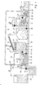
- the liquid manure processing plant comprises a first liquid manure container 1, a pre-treatment container 2, a liquid manure separation tank 3, a fertilizer tank 4, an evaporation unit 5, a water tank 6 and a second liquid manure storage tank 22.
- the first liquid manure container 1 has a first liquid manure pipe 7, in which there is inserted a first liquid manure pump 8 connected with the pre-treatment container 2.
- the first liquid manure pump 8 is controlled by a first float switch 28, this being built into the pre-treatment container 2, and being arranged to hold the liquid manure at a constant level in the pre-treatment container 2.
- pre-treatment container there is also a heating surface 18 which can be heated with the manure liquid phase from the separation tank 3, in that the temperature is held constant at an adjustable temperature by means of a thermostat 30 which controls a three-way valve 29.
- a mechanical stirrer 19 which can effect a slow stirring of the liquid manure in the container 2.
- a second liquid manure pipe 10 with a second liquid manure pump 11 leads from the pre-treatment container 2 to the upper area above the surface of the liquid manure in the separation tank 3, where the second liquid manure pipe 10 opens out into a liquid manure spreading element which can distribute same over the surface of the liquid manure.
- the separation tank 3 is described in more detail below.
- the third liquid manure pipe 16 has a third liquid manure pump 17 inserted, and leads alternatively to the heating surface 18 in the pre-treatment container 2 or via a pipe branch to the three-way valve 29.
- the third pump 17 is preferably a displacement pump capable of pumping at a constant, adjustable pump speed.
- the dry-stuff phase removal element 13, 14 leads to the fertilizer tank 4, which is in the form of a transportable container disposed under a tight cover 31, the lower edge of which is designed with a contact surface which can rest on the upper edge of the container 4.
- a pipe 27 opens out under the cover 31, said pipe 27 being connected via a pump 26 to an extraction opening in the evaporation unit 5, which is preferably an evaporation boiler with heating surface uppermost in the liquid volume, and having a steam dome over the liquid surface from which a steam pipe with compressor leads the steam from the steam dome to a condenser disposed below the heating surface, so that the steam condenses and radiates heat to the bottom area.
- the evaporation unit 5 which is preferably an evaporation boiler with heating surface uppermost in the liquid volume, and having a steam dome over the liquid surface from which a steam pipe with compressor leads the steam from the steam dome to a condenser disposed below the heating surface, so that the steam condenses and radiates heat to the bottom area.
- a water pipe 32 leads via the second liquid manure container 22 to a water tank 6.
- the pipe 32 is provided with a heat exchanger surface 34.
- a fourth liquid manure pipe 21 leads to the second liquid manure container 22, from which a fifth liquid manure pipe 23 with a fourth liquid manure pump 33 leads to the evaporation unit 5.
- a second three-way valve 35 from which a seventh liquid manure pipe 36 is led to a third liquid manure container 37.
- the liquid manure is pumped via the pump 8 through the first liquid manure pipe 7 to the pre-treatment container 2.
- the amount pumped is regulated by the first float switch 28 in the pre-treatment container 2.
- the pre-treatment container 2 is arranged for the regulation of the acidity of the liquid manure by means of an acid-forming microbiological culture. Its smallest size is thus dependent on the choice of operating temperature.
- the pre-treatment container must be capable of containing the average production of liquid manure for at least 24 hours, whereby the average time for which it is held in the container enables a sufficient formation of acid.
- the time for which the liq uid manure remains in the pre-treatment container is an average time, in that the contents of the container are constantly stirred with the stirrer 19 in order to ensure an even and uniform acid production, which is best achieved with a constant and uniform temperature.
- the temperature is held at the desired level by means of the adjustable thermostat 28, which controls the three-way valve 29 in such a manner that a fall in the temperature of the liquid manure in the pre-treatment container 2 results in a changeover of the three-way valve 29 to that position in which the liquid from the separation tank 3 is led through the heat exchanger in the pre-treatment container 2, and from here to the second liquid manure container 22, so that the heating surface 18 radiates heat to the liquid manure. If the temperature exceeds the desired level, the three-way valve is changed so that the liquid from the separation tank 3 is led around the pre-treatment container 2 directly to the second liquid manure container 22.
- the third liquid manure pump 17 pumps the liquid manure from the separation tank 3 through the pipes 16 and 21 to the second liquid manure container 22 at a constant speed.
- This speed can be regulated during the daily inspection, depending on the level of the liquid manure in the first container 1.
- the acidity of the liquid manure can alternatively be be regulated in the pre-treatment container 2 by means of the addition of, for example, sulphuric acid from the acid introduction container 9.
- the liquid manure is pumped from the pre-treatment container 2 via the second liquid manure pump 11 through the second liquid manure pipe 10 to the separation tank 3, which is discussed in more detail below.
- the dry-stuff phase of the liquid manure is removed from the separation tank 3 by means of the dry-stuff removal elements 13, 14, which drain the removed material of excess liquid phase and lead the drained material to the dry-stuff container 4.
- the fertilizer thus removed is sterile.
- the separated liquid phase is removed from the separation tank 3 through the third liquid manure pipe 16, and led to the second liquid manure container 22.
- the liquid manure in the second container 22 is heated and/or held at a high temperature by the condensation water which flows through the heat exchanger surface 34 on its way from the evaporator 5 to the water tank 6.
- the liquid manure which is sterile due to the heat treatment in the separation tank 3, is pumped from the second liquid manure container 22 via the fourth pump 33 through the fifth liquid manure pipe 23 to the evaporation unit 5, in which it is evaporated to a dry-stuff content of around 30% or slightly more, so that the concentrated liquid can be pumped portionwise by the fifth liquid manure pump 26 through the sixth liquid manure pipe 27 to the fertilizer container 4, and here combined with the liquid manure's dry-stuff phase.
- the evaporation unit 5 is preferably of the type described earlier in the application, and is therefore not described in more detail here.
- the water evaporated and recondensed in the evaporation unit is led through the water pipe 32 to the water tank 6, from where it can be pumped away for use as required.
- the quality of the water has proved to be quite satisfactory for use for feeding purposes, and can thus be recirculated within the agricultural operations.
- fig. 1 shows a three-way valve 35 via which the liquid manure can be led through a seventh liquid manure pipe 36 to a third liquid manure container 37. From this storage tank, the sterile liquid can be collected for spraying as fertilizer on the fields.
- This possibility is to be understood in the way that a plant in practice will usually be built either with the possibility of evaporation of the liquid manure, or with the possibility of direct spraying of the sterile liquid. However, investment in both possibilities in one and the same plant can be considered under certain conditions.
- the fertilizer produced contains the whole amount of the ammonia to be found in the starting material, and the fertilizing material produced has no tendency to give off ammonia during storage or spreading. This is contrary to the generally-known technique of storing and spreading of liquid manure, which normally results in an ammonia loss of around 30% or more.
- the fertilizer produced is in concentrated form, and is thus better able to bear the transport costs which are connected with its bringing out to remotely lying fields.
- the method according to the invention does not, however, need to be configured as described above. If the liquid manure producer has access to suffimerelyciently large field areas, and his own equipment for handling the sterile liquid, the second liquid manure container 22 can be made larger and the evaporation unit 5 omitted, in that the sterile liquid produced can be applied directly to the fields as fertilizing material. It is also possible to make the pre-treatment container 2 much smaller and arrange the method in such a way that the acidity of the liquid manure is always regulated solely by the addition of acid. In this and other ways it is possible to arrange the processing of the liquid manure in the most advantageous manner in each individual case. The only decisive factor is that one utilizes the stages of the method as presented in claim 1.
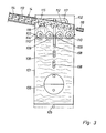
- Figures 2 and 3 show a schematic arrangement of a slurry separation tank 3 which forms of the plant for the execution of the method according to the invention in a particularly advantageous manner.
- the separation tank 3 has a container part 101 and a hood part 102, which with downwardly-directed flange surfaces 103 rests on upwardly-directed flange surfaces 104 on the container 101.
- a heating surface 106 which can be heated by a source of heat, here illustrated as an oil-burner 107.
- a heat exchanger 108 illustrated here as a pipe coil.
- the heat exchanger is an integral part of the second liquid manure pipe 10 in which the second liquid manure pump 11 is inserted.
- sieves 109 with an approximately semi-circular section are mounted in a substantially horizontal position.
- sieves 109 extend between to opposite walls in the container part 101, and are seated in a detachable manner on bracket supports (not shown) on the walls of the container part 101.
- each sieve 109 there is a conveyor worm 110 having two worm screws, one at each end, the spirals of these worm screws being in opposite directions, so that rotation of the worm screw in one direction will feed the transported material in towards the centre of the worm 110, while rotation of the worm 110 in the opposite direction will feed the transported material out towards one of the worm's ends.
- Each conveyor worm 110 is detachably seated in/on the container walls which support the corresponding sieve 109, in that the one end of the worm 110 is seated intern ally in the container part 101, while the second end of the worm 110 extends through the wall of the container part 110 to a slow-speed, driving gear motor, which can be common to all the conveyor worms 110 or separate for each individual worm.
- a float is provided for the float switch 111. This float and corresponding float arm are covered above by a plate (not shown) which can be a part of an adjacent sieve 109.
- the float switch 111 is mounted in a supported manner in the hood part 102.
- the float switch 111 controls the second liquid manure pump 11 in such a way that a fall in the level of the liquid in the tank 3 results in the pump being switched on, and is switched off again by the float switch 111 when the level of the liquid in the tank 3 has risen to the desired level.
- a dry-stuff removal element 14 is provided, this extending transversely in relation to the worms 110 and being inclined upwards in the direction of transport, and which is formed as a conveyor worm 112.
- this worm In its material intake area uppermost in the hood part 102, this worm is surrounded by a substantially semi-cylindrical shroud 115 which, at the outlet from the hood part 102, goes over to form a cylindrical worm conveyor shroud 113 in which is mounted a sieve tube 114.
- This sieve tube 114 surrounds the conveyor worm 112 and has an outside diameter which is somewhat smaller than the inside diameter of the worm shroud 113.
- the not-shown end of the conveyor worm 112 is mounted in a freely-rotatable manner, and at the end turning towards the hood part 102, its axle is seated in this part and extends through the wall of the hood to an externally-mounted, slow-speed gear motor 116, which drives the conveyor worm 112.
- a pipe 117 leads up into the upper part of the hood part 102 and branches out to a number of liquid manure spreading elements 118, illustrated here as sprinklers but which are in themselves components of a known kind, which can distribute the slurry-like liquid manure material evenly over the surface of the contents of the tank 3.
- a thermostat sensor 119 which is temperature adjustable and which controls the supply of heat from the heat source 107 to the heating surface 106.
- the separation tank 3 functions in the following manner:
- the second liquid manure pump 11 starts and pumps pre-treated liquid manure into the separation tank 3 via the spreading elements 118, which spread the liquid manure over the sieves 109.
- the manure's liquid phase seeps down through the sieves 109, in that solids with a sufficient particle size are retained by the sieves.
- the conveyor worms 110 and 112 are started and the tank 3 is filled.
- the heat source 107 can be activated so that the heating of the liquid manure is started.
- the float switch 111 controls the pump 11 so that this level is maintained during the further operation.
- the manure material By heating the pre-treated liquid manure up to 75°C or more, the manure material is sterilized, but at the same time a reaction takes place which results in the liquid manure material separating to form an almost clear liquid phase, which seeks towards the bottom area of the tank 3, and a dry-stuff-containing phase which seeks to move upwards and is partly pressed through the sieves 109.
- the heating of the liquid phase in the container part 101 means that the supplied liquid manure material is heated via the heat exchanger 108 in such a way that it is spread out in a hot and almost completely phase-separated condition.
- This heap of dry-stuff is removed by the conveyor worm 112, in that in its upwardly-inclined transport it is slightly compressed and thus drained of any accompanying liquid phase, which seeps out through the sieve tube 114 and runs back through the shroud 113 to the tank 3.
- the separated manure liquid phase is removed at a constantly-set speed by the third liquid manure pump 17 via the third liquid manure pipe 116, which is connected to the container opening 105.
- the apparatus according to the invention serves only to illustrate an advantageous example of an embodiment.
- the method according to the invention can be executed by means of other variants.
- this draining can be effected outside the separation tank; the slurry fed to the separation tank 3 can be added without preheating, or the heating can be effected with means other than those shown, and the supply does not necessarily have to be effected by spreading of the liquid manure material in the manner shown.
- this method is expedient in connection with the shown form of dry-stuff phase removal elements.
- the level and temperature control can be carried out in another way, and the heating can, for example, be effected with a hot-water plant or a steam boiler as heat source.
Landscapes
- Life Sciences & Earth Sciences (AREA)
- Chemical & Material Sciences (AREA)
- Soil Sciences (AREA)
- Engineering & Computer Science (AREA)
- Organic Chemistry (AREA)
- Environmental & Geological Engineering (AREA)
- Water Supply & Treatment (AREA)
- Chemical Kinetics & Catalysis (AREA)
- Manufacturing & Machinery (AREA)
- Hydrology & Water Resources (AREA)
- Environmental Sciences (AREA)
- Fertilizers (AREA)
- Treatment Of Sludge (AREA)
Applications Claiming Priority (2)
| Application Number | Priority Date | Filing Date | Title |
|---|---|---|---|
| DK1883/87 | 1987-04-10 | ||
| DK188387A DK188387A (da) | 1987-04-10 | 1987-04-10 | Fremgangsmaade til behandling af gylle og lignende slammaterialer og apparat til udoevelse af fremgangsmaaden |
Publications (1)
| Publication Number | Publication Date |
|---|---|
| EP0286616A2 true EP0286616A2 (de) | 1988-10-12 |
Family
ID=8108782
Family Applications (1)
| Application Number | Title | Priority Date | Filing Date |
|---|---|---|---|
| EP88850117A Withdrawn EP0286616A2 (de) | 1987-04-10 | 1988-04-08 | Verfahren zur Behandlung von Flüssigmist und ähnlichen schlammförmigen Materialien und Vorrichtung zur Durchführung des Verfahrens |
Country Status (6)
| Country | Link |
|---|---|
| EP (1) | EP0286616A2 (de) |
| JP (1) | JPH01119590A (de) |
| AU (1) | AU1444988A (de) |
| DK (1) | DK188387A (de) |
| NO (1) | NO881458L (de) |
| PT (1) | PT87175B (de) |
Cited By (11)
| Publication number | Priority date | Publication date | Assignee | Title |
|---|---|---|---|---|
| NL8802843A (nl) * | 1988-11-17 | 1990-06-18 | Pacques Bv | Werkwijze alsmede inrichting voor het behandelen van mest. |
| ES2034878A2 (es) * | 1991-04-26 | 1993-04-01 | Marti Alonso Carlos | Procedimiento para la obtencion de abonos y agua recuperada partiendo de purines porcinos e instalacion para la puesta en practica del mismo. |
| NL1007261C2 (nl) * | 1997-10-13 | 1999-04-14 | Bastiaan Dirk Frederik Piso | Mestzuiveringsinrichting. |
| RU2130002C1 (ru) * | 1997-08-12 | 1999-05-10 | Тарханов Олег Владимирович | Установка для переработки отходов органического происхождения в органоминеральные удобрения |
| RU2181709C2 (ru) * | 2000-05-24 | 2002-04-27 | Спевак Владимир Яковлевич | Линия для приготовления субстрата |
| ES2171111A1 (es) * | 2000-03-06 | 2002-08-16 | Sinae En Y Medio Ambiente S A | Procedimiento y planta para el tratamiento de purines. |
| ITTO20090445A1 (it) * | 2009-06-11 | 2010-12-12 | Marcopolo Engineering S P A Sistem I Ecologici | Dispositivo e procedimento per il trattamento di liquami organici, particolarmente liquami di origine zootecnica |
| EP2322025A1 (de) * | 2009-11-13 | 2011-05-18 | Jorgen Hyldgaard Staldservice A/S | Vorrichtung und Verfahren zur Säuerung von Tierdung |
| WO2014184595A1 (en) * | 2013-05-14 | 2014-11-20 | Utb Envirotec Zrt. | Process to recover soluble carbon and nutrients from organic waste |
| WO2017080558A1 (en) * | 2015-11-12 | 2017-05-18 | Jørgen Hyldgaard Staldservice A/S | Plant, its use and method for acidifying animal manure |
| EP3928608A1 (de) * | 2020-06-23 | 2021-12-29 | Danmarks Tekniske Universitet | Verfahren und schlammbehandlungsanlage zur reduzierung der methanemission aus schlamm |
Families Citing this family (2)
| Publication number | Priority date | Publication date | Assignee | Title |
|---|---|---|---|---|
| JP4841644B2 (ja) * | 1999-06-09 | 2011-12-21 | 株式会社Lixil | リモコン一体棚 |
| CN108895798A (zh) * | 2018-08-27 | 2018-11-27 | 洛阳龙须坡农牧有限公司 | 一种羊粪烘干回收装置 |
-
1987
- 1987-04-10 DK DK188387A patent/DK188387A/da unknown
-
1988
- 1988-04-06 NO NO881458A patent/NO881458L/no unknown
- 1988-04-06 PT PT87175A patent/PT87175B/pt not_active IP Right Cessation
- 1988-04-08 EP EP88850117A patent/EP0286616A2/de not_active Withdrawn
- 1988-04-08 JP JP63085484A patent/JPH01119590A/ja active Pending
- 1988-04-08 AU AU14449/88A patent/AU1444988A/en not_active Abandoned
Cited By (16)
| Publication number | Priority date | Publication date | Assignee | Title |
|---|---|---|---|---|
| NL8802843A (nl) * | 1988-11-17 | 1990-06-18 | Pacques Bv | Werkwijze alsmede inrichting voor het behandelen van mest. |
| ES2034878A2 (es) * | 1991-04-26 | 1993-04-01 | Marti Alonso Carlos | Procedimiento para la obtencion de abonos y agua recuperada partiendo de purines porcinos e instalacion para la puesta en practica del mismo. |
| RU2130002C1 (ru) * | 1997-08-12 | 1999-05-10 | Тарханов Олег Владимирович | Установка для переработки отходов органического происхождения в органоминеральные удобрения |
| NL1007261C2 (nl) * | 1997-10-13 | 1999-04-14 | Bastiaan Dirk Frederik Piso | Mestzuiveringsinrichting. |
| EP0908084A1 (de) * | 1997-10-13 | 1999-04-14 | PISO, Bastiaan D. F. | Vorrichtung um Mist zu reinigen |
| ES2171111A1 (es) * | 2000-03-06 | 2002-08-16 | Sinae En Y Medio Ambiente S A | Procedimiento y planta para el tratamiento de purines. |
| RU2181709C2 (ru) * | 2000-05-24 | 2002-04-27 | Спевак Владимир Яковлевич | Линия для приготовления субстрата |
| WO2010143142A1 (en) * | 2009-06-11 | 2010-12-16 | Marcopolo Engineering S.P.A. Sistemi Ecologici | Device and method for treating organic sewage, particularly sewage of zootechnic origin |
| ITTO20090445A1 (it) * | 2009-06-11 | 2010-12-12 | Marcopolo Engineering S P A Sistem I Ecologici | Dispositivo e procedimento per il trattamento di liquami organici, particolarmente liquami di origine zootecnica |
| EP2322025A1 (de) * | 2009-11-13 | 2011-05-18 | Jorgen Hyldgaard Staldservice A/S | Vorrichtung und Verfahren zur Säuerung von Tierdung |
| WO2014184595A1 (en) * | 2013-05-14 | 2014-11-20 | Utb Envirotec Zrt. | Process to recover soluble carbon and nutrients from organic waste |
| US10017398B2 (en) | 2013-05-14 | 2018-07-10 | Renew Technologies Ltd. | Process to recover soluble carbon and nutrients from organic waste |
| WO2017080558A1 (en) * | 2015-11-12 | 2017-05-18 | Jørgen Hyldgaard Staldservice A/S | Plant, its use and method for acidifying animal manure |
| EP3928608A1 (de) * | 2020-06-23 | 2021-12-29 | Danmarks Tekniske Universitet | Verfahren und schlammbehandlungsanlage zur reduzierung der methanemission aus schlamm |
| WO2021259436A1 (en) * | 2020-06-23 | 2021-12-30 | Danmarks Tekniske Universitet | Method and slurry treatment plant for reducing methane emission from slurry |
| US12448311B2 (en) | 2020-06-23 | 2025-10-21 | Stiesdal Skyclean A/S | Method and slurry treatment plant for reducing methane emission from slurry |
Also Published As
| Publication number | Publication date |
|---|---|
| NO881458D0 (no) | 1988-04-06 |
| DK188387A (da) | 1988-10-11 |
| PT87175A (pt) | 1988-05-01 |
| NO881458L (no) | 1988-10-11 |
| PT87175B (pt) | 1992-07-31 |
| AU1444988A (en) | 1988-10-13 |
| DK188387D0 (da) | 1987-04-10 |
| JPH01119590A (ja) | 1989-05-11 |
Similar Documents
| Publication | Publication Date | Title |
|---|---|---|
| EP0286616A2 (de) | Verfahren zur Behandlung von Flüssigmist und ähnlichen schlammförmigen Materialien und Vorrichtung zur Durchführung des Verfahrens | |
| US3323575A (en) | Apparatus and process for dehydrating waste solids concentrates | |
| CN101189190B (zh) | 有机性废弃物的处理设备以及处理方法 | |
| EP0142873A1 (de) | Verfahren und Anlage zur anaerobischen Gärung von festen Abfallmaterialien in Wasser in zwei Stufen | |
| EP1756258A2 (de) | Fermenter und fermentationsprozess | |
| US5256378A (en) | Apparatus for composting organic waste materials and method | |
| AU5100890A (en) | Waste water treatment process | |
| EP0498084B1 (de) | Verfahren zur Behandlung von Gülle | |
| US11000777B1 (en) | Apparatus and process for treating water | |
| CN110451752A (zh) | 一种自热式污泥及废碱废液的综合处理方法及装置 | |
| US7790044B2 (en) | Method and apparatus for separation of chemical materials from feces | |
| CA2205558A1 (en) | Apparatus for the purification of water contaminated with oil | |
| EP0126722A2 (de) | Anlage zur Verarbeitung organischer Stoffe | |
| RU2078060C1 (ru) | Способ обработки осадков сточных вод и устройство для его осуществления | |
| KR100321276B1 (ko) | 축산폐수및분뇨처리장치 | |
| RU2201910C2 (ru) | Устройство для ферментационной обработки жидкого навоза | |
| JP4198832B2 (ja) | 減圧脱水処理方法及び減圧脱水処理に使用するクッカー | |
| KR200230001Y1 (ko) | 분리형 고액분리기 | |
| EP1138185B1 (de) | Geschlossener und energie integrierender prozess zur behandlung der abwässer aus der tieraufzucht | |
| CN1044274A (zh) | 液肥及类似的淤浆材料之加工方法和实施该方法的装置 | |
| GB2282337A (en) | Treating organic waste in an anaerobic digester by passage through perforate channel | |
| US4719015A (en) | Apparatus and method for processing sewage scum | |
| KR100319410B1 (ko) | 수분을 함유한 유기성 폐기물을 처리하기 위한 시스템 및 방법 | |
| KR100365048B1 (ko) | 유기성 폐기물을 처리하기 위한 방법 및 시스템 | |
| JP2002518134A (ja) | 汚染された材料の液相の処理方法 |
Legal Events
| Date | Code | Title | Description |
|---|---|---|---|
| PUAI | Public reference made under article 153(3) epc to a published international application that has entered the european phase |
Free format text: ORIGINAL CODE: 0009012 |
|
| AK | Designated contracting states |
Kind code of ref document: A2 Designated state(s): AT BE CH DE ES FR GB GR IT LI LU NL SE |
|
| 17P | Request for examination filed |
Effective date: 19890413 |
|
| RAP1 | Party data changed (applicant data changed or rights of an application transferred) |
Owner name: HYDROMIX UDVIKLING A/S |
|
| STAA | Information on the status of an ep patent application or granted ep patent |
Free format text: STATUS: THE APPLICATION IS DEEMED TO BE WITHDRAWN |
|
| 18D | Application deemed to be withdrawn |
Effective date: 19911103 |