EP0286501B1 - Sicherheitsvorrichtung für einen Stoma-Apparat - Google Patents
Sicherheitsvorrichtung für einen Stoma-Apparat Download PDFInfo
- Publication number
- EP0286501B1 EP0286501B1 EP88400717A EP88400717A EP0286501B1 EP 0286501 B1 EP0286501 B1 EP 0286501B1 EP 88400717 A EP88400717 A EP 88400717A EP 88400717 A EP88400717 A EP 88400717A EP 0286501 B1 EP0286501 B1 EP 0286501B1
- Authority
- EP
- European Patent Office
- Prior art keywords
- end piece
- around
- ring
- snap
- face
- Prior art date
- Legal status (The legal status is an assumption and is not a legal conclusion. Google has not performed a legal analysis and makes no representation as to the accuracy of the status listed.)
- Expired - Lifetime
Links
- 239000002699 waste material Substances 0.000 claims abstract description 10
- 239000004820 Pressure-sensitive adhesive Substances 0.000 claims abstract description 3
- 210000001124 body fluid Anatomy 0.000 claims abstract 2
- 239000010839 body fluid Substances 0.000 claims abstract 2
- 230000001012 protector Effects 0.000 claims description 6
- 230000000694 effects Effects 0.000 claims 1
- 230000009471 action Effects 0.000 abstract description 3
- 239000000853 adhesive Substances 0.000 description 8
- 230000001070 adhesive effect Effects 0.000 description 8
- 239000012530 fluid Substances 0.000 description 8
- -1 polyethylene Polymers 0.000 description 6
- 239000004698 Polyethylene Substances 0.000 description 5
- 239000000463 material Substances 0.000 description 5
- 229920000573 polyethylene Polymers 0.000 description 5
- 239000004952 Polyamide Substances 0.000 description 3
- 229920002647 polyamide Polymers 0.000 description 3
- 239000004800 polyvinyl chloride Substances 0.000 description 3
- 239000000523 sample Substances 0.000 description 3
- 230000003187 abdominal effect Effects 0.000 description 2
- 239000003522 acrylic cement Substances 0.000 description 2
- 230000004888 barrier function Effects 0.000 description 2
- 230000000903 blocking effect Effects 0.000 description 2
- 230000005489 elastic deformation Effects 0.000 description 2
- 238000000034 method Methods 0.000 description 2
- 229920003023 plastic Polymers 0.000 description 2
- 239000004033 plastic Substances 0.000 description 2
- 229920000915 polyvinyl chloride Polymers 0.000 description 2
- 238000007789 sealing Methods 0.000 description 2
- 239000000126 substance Substances 0.000 description 2
- 230000002485 urinary effect Effects 0.000 description 2
- VGGSQFUCUMXWEO-UHFFFAOYSA-N Ethene Chemical compound C=C VGGSQFUCUMXWEO-UHFFFAOYSA-N 0.000 description 1
- 239000005977 Ethylene Substances 0.000 description 1
- 229920000219 Ethylene vinyl alcohol Polymers 0.000 description 1
- 239000004743 Polypropylene Substances 0.000 description 1
- 229920001328 Polyvinylidene chloride Polymers 0.000 description 1
- 239000004959 Rilsan Substances 0.000 description 1
- XTXRWKRVRITETP-UHFFFAOYSA-N Vinyl acetate Chemical compound CC(=O)OC=C XTXRWKRVRITETP-UHFFFAOYSA-N 0.000 description 1
- 240000008042 Zea mays Species 0.000 description 1
- 230000008901 benefit Effects 0.000 description 1
- 239000000470 constituent Substances 0.000 description 1
- 229920001577 copolymer Polymers 0.000 description 1
- 210000005069 ears Anatomy 0.000 description 1
- UFRKOOWSQGXVKV-UHFFFAOYSA-N ethene;ethenol Chemical compound C=C.OC=C UFRKOOWSQGXVKV-UHFFFAOYSA-N 0.000 description 1
- 239000004715 ethylene vinyl alcohol Substances 0.000 description 1
- 238000000605 extraction Methods 0.000 description 1
- 210000001035 gastrointestinal tract Anatomy 0.000 description 1
- 229920001903 high density polyethylene Polymers 0.000 description 1
- 239000004700 high-density polyethylene Substances 0.000 description 1
- 238000007455 ileostomy Methods 0.000 description 1
- 238000009434 installation Methods 0.000 description 1
- 238000012423 maintenance Methods 0.000 description 1
- 230000027939 micturition Effects 0.000 description 1
- 238000012986 modification Methods 0.000 description 1
- 230000004048 modification Effects 0.000 description 1
- 238000000465 moulding Methods 0.000 description 1
- 239000004745 nonwoven fabric Substances 0.000 description 1
- 229920000728 polyester Polymers 0.000 description 1
- 229920001155 polypropylene Polymers 0.000 description 1
- 229920000131 polyvinylidene Polymers 0.000 description 1
- 239000005033 polyvinylidene chloride Substances 0.000 description 1
- 230000008569 process Effects 0.000 description 1
- 238000000926 separation method Methods 0.000 description 1
- 210000002700 urine Anatomy 0.000 description 1
- 238000003466 welding Methods 0.000 description 1
Images


Classifications
-
- A—HUMAN NECESSITIES
- A61—MEDICAL OR VETERINARY SCIENCE; HYGIENE
- A61F—FILTERS IMPLANTABLE INTO BLOOD VESSELS; PROSTHESES; DEVICES PROVIDING PATENCY TO, OR PREVENTING COLLAPSING OF, TUBULAR STRUCTURES OF THE BODY, e.g. STENTS; ORTHOPAEDIC, NURSING OR CONTRACEPTIVE DEVICES; FOMENTATION; TREATMENT OR PROTECTION OF EYES OR EARS; BANDAGES, DRESSINGS OR ABSORBENT PADS; FIRST-AID KITS
- A61F5/00—Orthopaedic methods or devices for non-surgical treatment of bones or joints; Nursing devices; Anti-rape devices
- A61F5/44—Devices worn by the patient for reception of urine, faeces, catamenial or other discharge; Portable urination aids; Colostomy devices
- A61F5/445—Colostomy, ileostomy or urethrostomy devices
- A61F5/448—Means for attaching bag to seal ring
-
- A—HUMAN NECESSITIES
- A61—MEDICAL OR VETERINARY SCIENCE; HYGIENE
- A61F—FILTERS IMPLANTABLE INTO BLOOD VESSELS; PROSTHESES; DEVICES PROVIDING PATENCY TO, OR PREVENTING COLLAPSING OF, TUBULAR STRUCTURES OF THE BODY, e.g. STENTS; ORTHOPAEDIC, NURSING OR CONTRACEPTIVE DEVICES; FOMENTATION; TREATMENT OR PROTECTION OF EYES OR EARS; BANDAGES, DRESSINGS OR ABSORBENT PADS; FIRST-AID KITS
- A61F5/00—Orthopaedic methods or devices for non-surgical treatment of bones or joints; Nursing devices; Anti-rape devices
- A61F5/44—Devices worn by the patient for reception of urine, faeces, catamenial or other discharge; Portable urination aids; Colostomy devices
- A61F5/445—Colostomy, ileostomy or urethrostomy devices
- A61F2005/4486—Colostomy, ileostomy or urethrostomy devices with operable locking ring
Definitions
- the subject of the invention is a safety device for an ostomy fitting system.
- Ostomy devices are already known in many embodiments, that is to say devices allowing the removable attachment to the body of a user of a bag for collecting fluids and / or bodily waste. evacuated by patients who have undergone operations on the gastrointestinal tract or the urinary system, such as colostomies, ileostomies, urostomies, ureterostomies, all of these interventions being hereinafter referred to as ostomy.
- EP-A-0 089 138 which forms the preamble of claim 1, EP-A-0 171 255 or in FR-A-2 387 643, relating to one and the other to ostomy devices with collecting bag in the form of a disposable bag, or which can be emptied, and which is removably secured to a ring device fixed to the body of the user by an adhesive pad or by a belt.
- the collecting bag is put in place by a snap resulting from a push or pressure applied by the patient around the ostomy opening to make the parts of conjugate shape of the ring and of an integral part cooperate in a tight fitting. from the pocket.
- Such devices are designed so that the attachment of the pocket to the ring by pressure simultaneously seals the device on the one hand and, on the other hand, prevents untimely separation of the pocket from its ring. mounting.
- the known devices require that significant pressure be exerted by the patient during the assembly of the pocket and the ring. Since, however, the neighboring ostomy area is sensitive, generally painful, the application of high pressure only increases the discomfort of the user, so that known devices of the type mentioned are not fully satisfactory.
- a safety device for an ostomy fitting system comprising two elements, one of which is designed to be fixed around an artificial opening of the user's body.
- an appropriate fixing means such as, in particular, an adhesive means sensitive to pressure, a belt or any other similar means, and the other of which is integral with a collecting bag for collecting fluids and / or of bodily waste intended to be removably assembled to said first element by interlocking under the action of a pressure exerted during the bringing together of the two aforementioned elements
- the element which is associated with the pad forming a skin protector of the peristomal area and around the outlet of one or more probe (s) or the like which is (are) integral therewith and comprising a first tubular end piece consisting of an inner circular ring and a circular ring the outer area yes delimit between them a groove in which is suitable for fitting a second end piece associated with the pocket, said second end piece being suitable for being immobilized with respect to said first end piece
- the Applicant has set itself the goal of providing a safety device for an ostomy fitting system which is less restrictive in use and above all less unpleasant for the patient than those of known devices. , while ensuring perfect security of attachment, notwithstanding the use of a low or very low pressure for securing the pocket and the ring.
- the present invention also aims to allow the attachment of this device, which finds application regardless of the method of fixing the pad carrying the ring on the body of the user, using an adhesive product sensitive to the pressure or using a belt.
- an object of the invention to provide a device which makes it possible to modify the position slightly, easily and without risk to the patient. relative of the pocket and the ring, even when said pocket is partially filled with fluids or bodily waste.
- the present invention relates to a safety device for an ostomy fitting system comprising two elements, one of which is intended to be fixed around an artificial opening of the user's body using an appropriate fixing means.
- an adhesive means sensitive to pressure, a belt or any other similar means and the other of which is integral with a collecting bag for collecting fluids and / or bodily waste intended to be assembled in such a way removable from said first element by fitting under the action of a pressure exerted during the bringing together of the two aforementioned elements
- the element which is associated with the pad forming a skin protector of the peristomal zone and around the outlet of one or more probe (s) or the like which is (are) integral therewith and comprising a first tubular end piece consisting of an inner circular ring and an outer circular ring which define between them a groove in which is suitable for fitting a second end piece associated with the pocket, said second end piece being suitable for being immobilized relative to said first end piece when the two end pieces cooperate with interlocking by elastically deformable
- said latching means consist of hooks with elastic deformation attachment regularly arranged angularly on the outer ring of the first end piece, and having on the opposite face of the inner ring , a spout which immobilizes the second nozzle when the latter cooperates with the first nozzle.
- the number of attachment hooks is 4, 6, 8 or 12 depending on the diameter of the end pieces.
- the second end piece projects on its external face, an annular rib with two cut sides which is housed in the groove of the first end piece, when the two aforementioned end pieces are fitted by erasing the projections attachment hooks.
- the rotary member for locking comprises on its internal face recesses regularly offset from an angular point of view, the number of which corresponds to that of the attachment hooks arranged on the outer ring of the first end piece, and which allow the deformation of said hooks as well for the interlocking or the removal of said end pieces.
- the rotary member for locking, knurled or not on its outer face has a short lever facilitating the partial rotation of said member around the first nozzle.
- a blocking block of the rotary member housed, in operating condition, in a predetermined angular opening groove provided on the internal face of the rotary locking member, which defines the stroke of the rotary locking member.
- the invention further relates to a skin protector suitable for entering into the constitution of such a device comprising on a pad suitable for being fixed to the body of the user using an appropriate fixing means such as , in particular, that a pressure-sensitive means, a belt or any other similar means, a tubular tip projecting from the face of said pad opposite that intended to come into contact with the body of the user, said tip comprising a ring inner circular and a co-axial circular outer ring defining therebetween a groove in which is adapted to fit the end piece associated with a pocket and, around the first end piece, a rotary locking member which blocks elastically latching means deformable provided on the first end piece when it is rotated into a locking position, characterized in that the circular ring has spaces in which are housed the locking means uetage and in that the locking member comprises on its internal face recesses whose position and number correspond to those of the latching means.
- an appropriate fixing means such as , in particular, that a pressure-sensitive means, a belt or any other similar
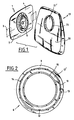
- Figures 1 to 10 relate to a safety device for ostomy fitting system according to the invention.
- This comprises an element 1, intended to be fixed around an artificial opening of the body of the user using an appropriate fixing means such as an adhesive means sensitive to pressure, known per se, and which is protected, as long as the device is not used, by a film 2 which can be easily removed by peeling (FIG. 11), or a belt 3 or any other similar means.
- an appropriate fixing means such as an adhesive means sensitive to pressure, known per se, and which is protected, as long as the device is not used, by a film 2 which can be easily removed by peeling (FIG. 11), or a belt 3 or any other similar means.
- Element 1 essentially comprises a pad 4 made of a flexible material, which can be square, rectangular, round or polygonal, for example, intended to form a skin protection of the peristomal area around which it is placed and maintained.
- This item 1 has an opening 5 concentric or substantially concentric to the stoma, and a mouthpiece 6 projecting from the face 7 of the pad 4 opposite to that carrying the adhesive material 8, FIG. 11, or when such material is not present, opposite the face in contact with the user's skin.
- the end-piece 6 is made integral with the shoe 4 by welding, for example of the thermal or high-frequency type or also by bonding by means of films compatible with the material constituting the end-piece 6.
- the pad 4 can be formed from a hydrophilic adhesive mass with a thickness between 0.5 and 3 mm, or from a very thin acrylic adhesive mass whose thickness is between a few microns and 200 microns approximately or by a combination of these two elements, that is to say, by providing around the stoma a hydrophilic adhesive gum and, at the periphery thereof, a thin acrylic adhesive mass.
- the end piece 6 can be made of polyethylene, high or low density, or of a copolymer of ethylene and vinyl acetate (EVA) or of polyvinyl chloride (PVC) or of a polyamide, by molding for example, and the films compatible for fixing the end piece to the skin protector are then advantageously films of polyethelene, PVC, polyamide, or complex barrier films or nonwovens based on polyester, polypropylene and / or polyethylene.
- EVA ethylene and vinyl acetate
- PVC polyvinyl chloride
- polyamide polyamide
- the end piece 6 comprises a circular base 9, which carries an internal circular ring 10 and an external circular ring 11 coaxial with the first and regularly cut by spaces in which are attached hooks 12, said coaxial rings delimiting between them a groove 10 ⁇ in which comes to fit the second end piece 21 associated with the pocket 20.
- the attachment hooks 12 have on the opposite face of the ring inner 10, a spout 12 ⁇ which immobilizes the second endpiece 21 secured to the pocket 20 for collecting fluids and / or bodily waste when said endpiece 21 cooperates with the endpiece 6 in the embedding condition.
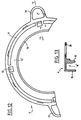
- the outer circular ring 11 has on the periphery of its outer face slight bulges 14, which prevent the extraction of a rotary locking member 15 when the latter is disposed around the ring 11, the latter also comprising on its face external a stud 13 for limiting the rotation span of the rotary member 15, housed in operating condition in a groove 30 of predetermined angular opening, for example 45 °, provided on the internal face of the rotary member 15, figure 3.
- Said member is or is not knurled on its external face 13 and has a short lever 18 which facilitates the partial rotation of said member around the external circular ring 11.
- the rotary member 15 also has, on its internal face, recesses 16 regularly offset from the angular point of view, the number of which corresponds to that of the attachment hooks 12, said recesses allowing the elastic deformation of the hooks 12 when the two ends 6 and 21 are fitted and / or when one of them is extracted the other.
- the safety device for ostomy fitting system also comprises an element 19 capable of cooperating, in a removable manner, with element 1.
- This element consists essentially of the bag 20 for collecting fluids and / or body waste suitable for being evacuated through the nozzle 6 and which comprises a wall 22 ⁇ (FIG. 11), pierced with a hole 21 ⁇ through which fluids or body waste penetrate inside the pocket, which can be of the type to be discarded, or to be emptied, according to the wishes of the practice.
- a polyethylene, or PVC, or polyamide film like that known under the registered trademark RILSAN
- a complex barrier film of the polyethylene / EVA / polyvinylidene chloride / EVA / polyethylene type such as those known under the trademark SARANEX from the company DOW CHEM
- the pocket 20 is associated with the end piece 21, advantageously made of the same plastic material as the end piece 6, for example made of high density polyethylene, and securely joined to the pocket 20, on which it is welded or glued, as indicated above, so that its axis is coaxial with that of the hole 21 ⁇ .
- Said end piece 21 has an annular rib 22 with two cut sides 22a, 22b projecting from its external face which is housed in the groove 10 ⁇ , elastically erasing the nozzles 12s of the hooks 12 of the first end piece 6 when the two end pieces 6 and 21 are nested.
- the end piece 21 also comprises projecting on its internal face a deformable plastic annular lip 23 which, in known manner, ensures the sealing of the device against the fluids and / or waste collected.
- the fitting 21 is fitted into the fitting 6, making sure beforehand that the rotary member for locking 15 is arranged so that the recesses 26 are opposite.
- the hooks are elastically deformed (position in phantom in Figure 8) and enter the recesses 16, when the tip 21 is positioned at the bottom of the groove 10 ⁇ , of the endpiece 6, said hooks return to their initial position (solid line position in FIG. 8) ensuring the maintenance of the endpiece 21 in said groove 10 ⁇ by the nozzles 12 ⁇ which are then positioned against one cut sides 22b of the annular rib 22 of said end piece 21.
- Partial rotation of the rotary member 15 is then carried out for locking the pocket 20 relative to the shoe 4, this rotation being limited at the end of travel by the stop of the blocking stud 13 on one of the edges of the predetermined angular opening groove 30 provided on the internal face of the rotary member for locking 15.
- the two end pieces 6 and 21 then being fitted and locked, a rotation of the element 19 relative to element 1 is possible and the patient can take advantage of it, to slightly modify the position of the bag 20, even when the latter is partially filled, without detaching it from the pad 4.
- the base 9 of the endpiece 6 can also be provided in diametrically opposite zones with ears 31 and 32 for attaching a belt, not shown.
- Such an embodiment which also includes a pad 4 with pressure-sensitive adhesive is of particular interest for patients with an invaginated ostomy.
- the device of the invention When the device of the invention is used for urostomies or ureterostomies at least one or more catheters, probes or the like, can be fixed to the pad, as known per se, and without this resulting in structural modifications of the other parts of the device according to the invention.
Landscapes
- Health & Medical Sciences (AREA)
- Epidemiology (AREA)
- Nursing (AREA)
- Orthopedic Medicine & Surgery (AREA)
- Engineering & Computer Science (AREA)
- Biomedical Technology (AREA)
- Heart & Thoracic Surgery (AREA)
- Vascular Medicine (AREA)
- Life Sciences & Earth Sciences (AREA)
- Animal Behavior & Ethology (AREA)
- General Health & Medical Sciences (AREA)
- Public Health (AREA)
- Veterinary Medicine (AREA)
- Orthopedics, Nursing, And Contraception (AREA)
- Cookers (AREA)
Claims (9)
- Sicherheitsvorrichtung für ein System betreffend einen künstlichen Körperausgang bestehend aus zwei Elementen (1, 19), wovon eines dazu vorgesehen ist, um rund um einen künstlichen Ausgang des Körpers des Benützers mit Hilfe eines geeigneten Befestigungsmittels, wie insbesondere eines druckempfindlichen Haftmittels, eines Gürtels oder jedes anderen ähnlichen Mittels befestigt zu werden, und das andere fest mit einem Sammelbeutel zum Sammeln von Flüssigkeiten und/oder Körperausscheidungen (20) verbunden ist, der durch Einrasten unter Ausübung eines Druckes bei Annäherung beider Elemente lösbar an das erste Element anschließbar ist, wobei das Element (1), welches eine Unterlage (4) zugeordnet ist, die einen Hautschutz der peristomialen Zone und rund den Ausgang einer oder mehrerer Sonden oder ähnlichem bildet, die mit ihr fest verbunden sind, und ein erstes röhrenförmiges Ansatzstück (6) aufweisen, welches aus einem kreisförmigen inneren Ring (10) und einem kreisförmigen äußeren Ring (11) besteht, welche zwischen ihnen einen Hals (10') begrenzen, in welchem ein Zweites Ansatzstück (21) angeschlossen werden kann, das dem Beutel (20) zugeordnet ist, wobei das Zweite Ansatzstück (21) dazu geeignet ist, bezüglich des ersten Ansatzstücks (6) fixiert zu werden, wenn die Zwei miteinander verbundenen Ansatzstücke (6, 21) mit einer elastisch deformierbaren Einklinkvorrichtung (12) zusammenwirken, welche an dem ersten Ansatzstück (6) vorgesehen ist, dadurch gekennzeichnet, daß sie rund um das röhrenförmige Ansatzstück (6) einen drehbaren Teil (15) aufweist, um an der elastisch deformierbaren Einklinkvorrichtung (12) einzurasten, wenn sie durch Drehen in die Verriegelungsstellung gebracht wird, wobei die Einklinkvorrichtung (12) in den Zwischenräumen des kreisförmigen äußeren Ringes (11) des ersten Ansatzstücks (6) untergebracht ist.
- Vorrichtung nach Anspruch 1, dadurch gekennzeichnet, daß die Einklinkvorrichtungen aus elastisch verformbaren Befestigungshaken (12) bestehen, welche in regelmäßigen Winkelabständen auf dem äußeren Ring (11) des ersten Ansatzstückes angeordnet sind, und welche auf der Seite, die dem inneren Ring (10) zugewandt ist, einen Vorsprung (12') aufweisen, der das zweite Ansatzstück (21) beim Zusammenfügen mit dem ersten Ansatzstück (6) fixiert.
- Vorrichtung nach Anspruch 2, dadurch gekennzeichnet, daß die Anzahl der Befestigungshaken (12) in Abhängigkeit des Durchmessers der Ansatzstücke (6, 21) 4, 6, 8 oder 12 beträgt.
- Vorrichtung nach Anspruch 1, dadurch gekennzeichnet, daß das zweite Ansatzstück (21) an seiner Außenseite eine vorspringende ringförmige Rippe (22) mit zwei schrägen Flächen (22a, 22b) aufweist, welche sich in die Rille (10') des ersten Ansatzstückes (6) einpaßt, wenn die beiden oben genannten Ansatzstücke (6, 21) eingerastet werden, indem die Vorsprünge (12') der Befestigungshaken (12) zurückweichen.
- Vorrichtung nach einem der Ansprüche 2 bis 4, dadurch gekennzeichnet, daß der drehbare Teil zur Verriegelung (15) an seiner inneren Fläche Auskehlungen (16) aufweist, welche in gleichen Winkelabstanden regelmäßig versetzt sind und deren Anzahl derjenigen der Befestigungshaken (12) entspricht, welche an dem äußeren Ring des ersten Ansatzstückes angeordnet sind, und welche die Verformung dieser Haken (12) zum Einrasten und Ausrasten der Ahsatzstücke (6, 21) gewährleisten.
- Vorrichtung nach Anspruch 5, dadurch gekennzeichnet, daß der drehbare Teil zur Verriegelung (15) auf seiner äußeren Berandung (17) gerändelt ist oder nicht und einen kurzen Hebel (18) aufweist, welcher eine teilweise Verdrehung dieses Teils um das erste Ansatzstück (6) erleichtert.
- Vorrichtung nach einem der vorgehenden Ansprüche, dadurch gekennzeichnet, daß auf der äußeren Fläche des äußeren Ringes (11) des ersten Ansatzstückes (6) ein Blockiersteckstück (13) für den drehbaren Teil (15) vorgesehen ist, welches sich im Betriebszustand in einem Schlitz (30) mit vorgegebener Winkelöffnung befindet, der auf der inneren Fläche des drehbaren Verriegelungsteiles (15) vorgesehen ist.
- Vorrichtung nach einem der vorgehenden Ansprüche, dadurch gekennzeichnet, daß das Ansatzstück (6), das mit der Unterlage (4) fest verbunden ist, auf einem Unterteil (9) ausgebildet ist und daß letzterer Befestigungsschlaufen (31, 32) oder ähnliches für einen Befestigungsgürtel (3) aufweist.
- Hautschutz, der für den Einbau in eine Vorrichtung für einen künstlichen Körperausgang nach einem der Ansprüche 1 bis 8 geeignet ist, der auf einer Unterlage (4), die mittels eines geeigneten Befestigungsmittels, wie insbesondere eines druckempfindlichen Mittels, eines Gürtels (3) oder jedes anderen ähnlichen Mittels an dem Körper des Benützers befestigbar ist, ein röhrenförmiges Ansatzstück (6) aufweist, das auf der Fläche der Unterlagen vorspringt, welche jener gegenüberliegt, die mit dem Körper des Benützers in Kontakt kommt, und welches einen inneren kreisförmigen Ring (10) und einen koaxialen äußeren kreisförmigen Ring (11) aufweist, die dazwischen koaxial einen Hals (10') begrenzen, in welchem das Ansatzstück (21), welches einem Beutel (20) zugeordnet ist, und rund um das erste Ansatzstück (6) ein drehbarer Teil (15) zur Verriegelung angeschlossen werden kann, der die elastisch deformierbare, an dem ersten Ansatzstück vorgesehene Einklinkvorrichtung (12) blockiert, nachdem er durch Drehung in eine Verriegelungsstellung gebracht wird, dadurch gekennzeichnet, daß der kreisförmige Ring (11) Unterbrechungen aufweist, in welchen sich die Einklinkvorrichtung (12) befindet, und daß der Verriegelungsteil (15) an seiner Innenfläche (16) Vorsprünge aufweist, deren Position und Zahl jenen der Einklinkvorrichtung (12) entspricht.
Priority Applications (1)
| Application Number | Priority Date | Filing Date | Title |
|---|---|---|---|
| AT88400717T ATE89150T1 (de) | 1987-04-10 | 1988-03-24 | Sicherheitsvorrichtung fuer einen stoma-apparat. |
Applications Claiming Priority (2)
| Application Number | Priority Date | Filing Date | Title |
|---|---|---|---|
| FR8705146A FR2613613B1 (fr) | 1987-04-10 | 1987-04-10 | Dispositif d'assemblage pour poche d'ostomie |
| FR8705146 | 1987-04-10 |
Publications (2)
| Publication Number | Publication Date |
|---|---|
| EP0286501A1 EP0286501A1 (de) | 1988-10-12 |
| EP0286501B1 true EP0286501B1 (de) | 1993-05-12 |
Family
ID=9350024
Family Applications (1)
| Application Number | Title | Priority Date | Filing Date |
|---|---|---|---|
| EP88400717A Expired - Lifetime EP0286501B1 (de) | 1987-04-10 | 1988-03-24 | Sicherheitsvorrichtung für einen Stoma-Apparat |
Country Status (8)
| Country | Link |
|---|---|
| US (1) | US4929245A (de) |
| EP (1) | EP0286501B1 (de) |
| AT (1) | ATE89150T1 (de) |
| CA (1) | CA1322506C (de) |
| DE (2) | DE3880875T2 (de) |
| ES (1) | ES2005532A4 (de) |
| FR (1) | FR2613613B1 (de) |
| SU (1) | SU1724004A3 (de) |
Families Citing this family (31)
| Publication number | Priority date | Publication date | Assignee | Title |
|---|---|---|---|---|
| GB8813967D0 (en) * | 1988-06-13 | 1988-07-20 | Squibb & Sons Inc | Ostomy bag coupling |
| GB2225951B (en) * | 1988-12-13 | 1992-06-24 | Squibb & Sons Inc | Ostomy coupling |
| GB2227667B (en) * | 1989-02-03 | 1992-07-29 | Squibb & Sons Inc | Ostomy coupling |
| CA2028618C (en) * | 1989-11-17 | 2001-12-11 | Peter Leslie Steer | Ostomy coupling |
| US5178614A (en) * | 1991-08-29 | 1993-01-12 | Mcdowell Charles E | Protective shield for a stoma pough |
| JP3428989B2 (ja) * | 1992-05-12 | 2003-07-22 | イー.アール.スクィブ アンド サンズ,インコーポレイテッド | 樹脂製品の成形方法およびこれによる製品 |
| DK170206B1 (da) * | 1993-02-22 | 1995-06-19 | Coloplast As | Stomikobling |
| GB2283176B (en) * | 1993-10-28 | 1998-03-11 | Squibb & Sons Inc | Ostomy coupling |
| CA2134148C (en) * | 1993-10-28 | 2005-03-08 | Peter Leslie Steer | Male incontinence device |
| GB9507666D0 (en) * | 1995-04-13 | 1995-05-31 | Squibb & Sons Inc | Ostomy coupling |
| DK0737456T3 (da) * | 1995-04-13 | 2004-10-04 | Bristol Myers Squibb Co | Ostomikobling |
| GB2316317B (en) * | 1996-08-20 | 2000-07-19 | Bristol Myers Squibb Co | An ostomy coupling |
| US8142406B2 (en) | 2005-12-07 | 2012-03-27 | Convatec Technologies Inc. | Ostomy coupling |
| US9149385B2 (en) * | 2007-06-01 | 2015-10-06 | Unomedical A/S | Urine measuring vessel and hose connection |
| BR112012002517B8 (pt) * | 2009-08-04 | 2021-06-22 | Coloplast As | dispositivo de ostomia de duas peças com ajuda orientadora para acoplamento |
| US8316985B2 (en) * | 2009-12-23 | 2012-11-27 | Mark Bain | Methods and devices for sound abatement of an abdominal stoma |
| BR112012018435B1 (pt) * | 2010-02-01 | 2021-05-18 | Coloplast A/S | aparelho de ostomia |
| EP2563301B1 (de) * | 2010-04-29 | 2015-04-08 | Coloplast A/S | Personaliersierbare sammelvorrichtung |
| US9522079B2 (en) * | 2010-06-04 | 2016-12-20 | Coloplast A/S | Filter with an extension element |
| US10010443B2 (en) * | 2011-07-01 | 2018-07-03 | Coloplast A/S | Coupling for an ostomy appliance |
| RU2573054C2 (ru) | 2011-09-14 | 2016-01-20 | Колопласт А/С | Мешок для сбора человеческих экскрементов |
| BR112014020900B1 (pt) * | 2012-03-06 | 2021-06-01 | Coloplast A/S | Anel de travamento para um acoplamento para um aparelho de ostomia, acoplamento para um saco de ostomia, e, aparelho de ostomia |
| US9993364B2 (en) | 2013-09-26 | 2018-06-12 | 3 West C, Llc | Ostomy bag |
| WO2015048446A1 (en) | 2013-09-26 | 2015-04-02 | 3 West C, Llc | Ostomy bag |
| WO2016025314A2 (en) * | 2014-08-11 | 2016-02-18 | Western Connecticut Health Network, Inc. | Systems and methods wound drainage management |
| DK178391B1 (da) * | 2015-03-18 | 2016-10-17 | Multi-Lock Aps | Stomianordning |
| RU2732434C2 (ru) * | 2015-10-20 | 2020-09-16 | Колопласт А/С | Приспособление для стомического использования |
| CN106420146B (zh) * | 2016-08-19 | 2018-09-04 | 丽水市人民医院 | 一种可转动的造口袋及其使用方法 |
| US9919133B1 (en) | 2016-12-28 | 2018-03-20 | Abdullatif E. A. H. Al-Terki | Surgical drain anchoring device |
| US11298257B2 (en) * | 2017-03-22 | 2022-04-12 | 3 West C, Llc. | Ostomy apparatuses and related methods |
| CN107638244A (zh) * | 2017-10-10 | 2018-01-30 | 华中科技大学同济医学院附属协和医院 | 一种两件式造瘘装置 |
Citations (1)
| Publication number | Priority date | Publication date | Assignee | Title |
|---|---|---|---|---|
| EP0255310A1 (de) * | 1986-07-31 | 1988-02-03 | E.R. Squibb & Sons, Inc. | Ostomiekupplung |
Family Cites Families (11)
| Publication number | Priority date | Publication date | Assignee | Title |
|---|---|---|---|---|
| US2973759A (en) * | 1956-11-16 | 1961-03-07 | Jr Mis William S Plymale | Colostomy unit |
| US3736934A (en) * | 1971-09-21 | 1973-06-05 | A Hennessy | Surgical drainage appliance |
| NZ186585A (en) * | 1977-03-30 | 1981-03-16 | Kingsdown Medical Consultants | Coupling for joining pad or dressing to an ostomy bag |
| GB1553450A (en) * | 1977-04-18 | 1979-09-26 | Squibb & Sons Inc | Ostomy bag |
| GB1568860A (en) * | 1978-03-21 | 1980-06-04 | Kingsdown Medical Consultants | Coupling for an ostomy bag |
| GB2121902B (en) * | 1982-03-11 | 1985-07-31 | Craig Med Prod Ltd | A coupling for an ostomy bag |
| GB8403237D0 (en) * | 1984-02-07 | 1984-03-14 | Edwards J V | Ostomy appliance |
| DE3417183A1 (de) * | 1984-05-09 | 1985-11-14 | Gerald Dr. 8000 München Hauer | Anus-praeter-versorgungssystem |
| US4610676A (en) * | 1984-05-17 | 1986-09-09 | Hollister Incorporated | Ostomy appliance coupling ring construction |
| GB2163959A (en) * | 1984-08-08 | 1986-03-12 | Craig Med Prod Ltd | Ostomy appliance |
| GB8618693D0 (en) * | 1986-07-31 | 1986-09-10 | Craig Med Prod Ltd | Ostomy coupling |
-
1987
- 1987-04-10 FR FR8705146A patent/FR2613613B1/fr not_active Expired - Fee Related
-
1988
- 1988-03-24 EP EP88400717A patent/EP0286501B1/de not_active Expired - Lifetime
- 1988-03-24 ES ES88400717T patent/ES2005532A4/es active Pending
- 1988-03-24 DE DE8888400717T patent/DE3880875T2/de not_active Expired - Fee Related
- 1988-03-24 DE DE198888400717T patent/DE286501T1/de active Pending
- 1988-03-24 AT AT88400717T patent/ATE89150T1/de not_active IP Right Cessation
- 1988-04-08 US US07/179,629 patent/US4929245A/en not_active Expired - Lifetime
- 1988-04-08 CA CA000563716A patent/CA1322506C/fr not_active Expired - Fee Related
- 1988-04-09 SU SU884355538A patent/SU1724004A3/ru active
Patent Citations (1)
| Publication number | Priority date | Publication date | Assignee | Title |
|---|---|---|---|---|
| EP0255310A1 (de) * | 1986-07-31 | 1988-02-03 | E.R. Squibb & Sons, Inc. | Ostomiekupplung |
Also Published As
| Publication number | Publication date |
|---|---|
| ES2005532A4 (es) | 1989-03-16 |
| SU1724004A3 (ru) | 1992-03-30 |
| US4929245A (en) | 1990-05-29 |
| ATE89150T1 (de) | 1993-05-15 |
| DE286501T1 (de) | 1989-03-30 |
| FR2613613B1 (fr) | 1990-12-07 |
| CA1322506C (fr) | 1993-09-28 |
| EP0286501A1 (de) | 1988-10-12 |
| FR2613613A1 (fr) | 1988-10-14 |
| DE3880875D1 (de) | 1993-06-17 |
| DE3880875T2 (de) | 1993-08-26 |
Similar Documents
| Publication | Publication Date | Title |
|---|---|---|
| EP0286501B1 (de) | Sicherheitsvorrichtung für einen Stoma-Apparat | |
| EP0270400B1 (de) | Ostomie-Vorrichtung | |
| EP1663084B1 (de) | Verbindende Ostomie-Vorrichtung | |
| EP0433102B1 (de) | Ostomiekupplung | |
| EP0653196B1 (de) | Ventil und innendrucksteuervorrichtung für Ostomiebeutel | |
| EP0369923B1 (de) | Verschlusselement zur Kontrolle von Ileokolostomie | |
| FR2626464A1 (fr) | Dispositif medico-chirurgical a poche receptrice | |
| FR2474858A1 (fr) | Dispositif de vidange a robinet pour poche d'urostomie | |
| CH620357A5 (de) | ||
| FR2523434A1 (fr) | Accessoire d'ostomie et fixation a plastron pour cet accessoire | |
| FR2523436A1 (fr) | Poche collectrice pour ostomie | |
| FR2638634A1 (de) | ||
| WO1981001957A1 (fr) | Dispositif pour recueillir les urines d'incontinents masculins | |
| EP0990429B1 (de) | In einem Ostomiebeutel integriertes Filter- und Entlüftungssystem | |
| EP0149391B1 (de) | Vorrichtung zum Abführen der Urins aus einer Ureterostomie | |
| FR2809015A1 (fr) | Seringue hypodermique de surete et porte-aiguille pour celui-ci | |
| FR2662934A1 (fr) | Appareillage pour stomie. | |
| FR2775893A1 (fr) | Raccord pour appareillage pour stomie et appareillage pour stomie comprenant un tel raccord | |
| FR2638633A1 (fr) | Dispositif medico-chirurgical a poche collectrice | |
| FR2721204A1 (fr) | Anneau convexe pour stomies invaginées. | |
| FR2746633A1 (fr) | Raccord pour appareillage pour stomie et appareillage pour stomie comprenant un tel raccord | |
| FR2548014A1 (fr) | Poche pour stomise | |
| EP0461007A1 (de) | Stomavorrichtung | |
| FR2690333A1 (fr) | Dispositif de raccord d'une poche et d'un porte-poche d'appareillage pour stomie. | |
| WO2020025476A1 (fr) | Dispositif permettant de collecter d'éventuels calculs rénaux présents dans un flux d'urine, destiné essentiellement à un utilisateur masculin |
Legal Events
| Date | Code | Title | Description |
|---|---|---|---|
| PUAI | Public reference made under article 153(3) epc to a published international application that has entered the european phase |
Free format text: ORIGINAL CODE: 0009012 |
|
| AK | Designated contracting states |
Kind code of ref document: A1 Designated state(s): AT BE CH DE ES GB IT LI NL SE |
|
| ITCL | It: translation for ep claims filed |
Representative=s name: STUDIO ASSOC. MARIETTI & PIPPARELLI |
|
| TCNL | Nl: translation of patent claims filed | ||
| GBC | Gb: translation of claims filed (gb section 78(7)/1977) | ||
| TCAT | At: translation of patent claims filed | ||
| DET | De: translation of patent claims | ||
| 17P | Request for examination filed |
Effective date: 19890223 |
|
| 17Q | First examination report despatched |
Effective date: 19901001 |
|
| GRAA | (expected) grant |
Free format text: ORIGINAL CODE: 0009210 |
|
| AK | Designated contracting states |
Kind code of ref document: B1 Designated state(s): AT BE CH DE ES GB IT LI NL SE |
|
| PG25 | Lapsed in a contracting state [announced via postgrant information from national office to epo] |
Ref country code: IT Free format text: LAPSE BECAUSE OF FAILURE TO SUBMIT A TRANSLATION OF THE DESCRIPTION OR TO PAY THE FEE WITHIN THE PRESCRIBED TIME-LIMIT;WARNING: LAPSES OF ITALIAN PATENTS WITH EFFECTIVE DATE BEFORE 2007 MAY HAVE OCCURRED AT ANY TIME BEFORE 2007. THE CORRECT EFFECTIVE DATE MAY BE DIFFERENT FROM THE ONE RECORDED. Effective date: 19930512 Ref country code: SE Effective date: 19930512 |
|
| REF | Corresponds to: |
Ref document number: 89150 Country of ref document: AT Date of ref document: 19930515 Kind code of ref document: T |
|
| GBT | Gb: translation of ep patent filed (gb section 77(6)(a)/1977) |
Effective date: 19930519 |
|
| REF | Corresponds to: |
Ref document number: 3880875 Country of ref document: DE Date of ref document: 19930617 |
|
| PG25 | Lapsed in a contracting state [announced via postgrant information from national office to epo] |
Ref country code: ES Free format text: LAPSE BECAUSE OF FAILURE TO SUBMIT A TRANSLATION OF THE DESCRIPTION OR TO PAY THE FEE WITHIN THE PRESCRIBED TIME-LIMIT Effective date: 19930823 |
|
| RAP2 | Party data changed (patent owner data changed or rights of a patent transferred) |
Owner name: LABORATOIRES MERCK-CLEVENOT |
|
| REG | Reference to a national code |
Ref country code: CH Ref legal event code: PUE Owner name: LABORATOIRES MERCK-CLEVENOT |
|
| REG | Reference to a national code |
Ref country code: GB Ref legal event code: 732E |
|
| NLS | Nl: assignments of ep-patents |
Owner name: LABORATOIRES MERCK CLEVENOT TE NOGENT-SUR-MARNE, F |
|
| BECA | Be: change of holder's address |
Free format text: 930512 LABORATOIRES *MERCK CLEVENOT:5 a 9 RUE ANQUETIL, F-94736 NOGENT-SUR-MARNE |
|
| BECH | Be: change of holder |
Free format text: 930512 LABORATOIRES *MERCK CLEVENOT |
|
| PLBI | Opposition filed |
Free format text: ORIGINAL CODE: 0009260 |
|
| 26 | Opposition filed |
Opponent name: E.R. SQIBB & SONS, INC. Effective date: 19940210 |
|
| NLR1 | Nl: opposition has been filed with the epo |
Opponent name: SQUIBB & SONS, INC. |
|
| RAP2 | Party data changed (patent owner data changed or rights of a patent transferred) |
Owner name: B. BRAUN BIOTROL |
|
| NLT2 | Nl: modifications (of names), taken from the european patent patent bulletin |
Owner name: B. BRAUN BIOTROL |
|
| PLBM | Termination of opposition procedure: date of legal effect published |
Free format text: ORIGINAL CODE: 0009276 |
|
| STAA | Information on the status of an ep patent application or granted ep patent |
Free format text: STATUS: OPPOSITION PROCEDURE CLOSED |
|
| 27C | Opposition proceedings terminated |
Effective date: 19951112 |
|
| REG | Reference to a national code |
Ref country code: CH Ref legal event code: PUE Owner name: LABORATOIRES MERCK-CLEVENOT TRANSFER- B. BRAUN BIO |
|
| NLR2 | Nl: decision of opposition | ||
| REG | Reference to a national code |
Ref country code: GB Ref legal event code: IF02 |
|
| PGFP | Annual fee paid to national office [announced via postgrant information from national office to epo] |
Ref country code: CH Payment date: 20030218 Year of fee payment: 16 |
|
| PGFP | Annual fee paid to national office [announced via postgrant information from national office to epo] |
Ref country code: GB Payment date: 20030226 Year of fee payment: 16 |
|
| PGFP | Annual fee paid to national office [announced via postgrant information from national office to epo] |
Ref country code: NL Payment date: 20030228 Year of fee payment: 16 |
|
| PGFP | Annual fee paid to national office [announced via postgrant information from national office to epo] |
Ref country code: AT Payment date: 20030304 Year of fee payment: 16 |
|
| PGFP | Annual fee paid to national office [announced via postgrant information from national office to epo] |
Ref country code: BE Payment date: 20030310 Year of fee payment: 16 |
|
| PGFP | Annual fee paid to national office [announced via postgrant information from national office to epo] |
Ref country code: DE Payment date: 20030311 Year of fee payment: 16 |
|
| PG25 | Lapsed in a contracting state [announced via postgrant information from national office to epo] |
Ref country code: AT Free format text: LAPSE BECAUSE OF NON-PAYMENT OF DUE FEES Effective date: 20040324 Ref country code: GB Free format text: LAPSE BECAUSE OF NON-PAYMENT OF DUE FEES Effective date: 20040324 |
|
| PG25 | Lapsed in a contracting state [announced via postgrant information from national office to epo] |
Ref country code: CH Free format text: LAPSE BECAUSE OF NON-PAYMENT OF DUE FEES Effective date: 20040331 Ref country code: BE Free format text: LAPSE BECAUSE OF NON-PAYMENT OF DUE FEES Effective date: 20040331 Ref country code: LI Free format text: LAPSE BECAUSE OF NON-PAYMENT OF DUE FEES Effective date: 20040331 |
|
| BERE | Be: lapsed |
Owner name: LABORATOIRES *MERCK CLEVENOT Effective date: 20040331 |
|
| PG25 | Lapsed in a contracting state [announced via postgrant information from national office to epo] |
Ref country code: NL Free format text: LAPSE BECAUSE OF NON-PAYMENT OF DUE FEES Effective date: 20041001 Ref country code: DE Free format text: LAPSE BECAUSE OF NON-PAYMENT OF DUE FEES Effective date: 20041001 |
|
| REG | Reference to a national code |
Ref country code: CH Ref legal event code: PL |
|
| GBPC | Gb: european patent ceased through non-payment of renewal fee |
Effective date: 20040324 |
|
| NLV4 | Nl: lapsed or anulled due to non-payment of the annual fee |
Effective date: 20041001 |