EP0285997A1 - Elektronische Frankiermaschine mit einer grossen Anzahl von Hilfszählern - Google Patents
Elektronische Frankiermaschine mit einer grossen Anzahl von Hilfszählern Download PDFInfo
- Publication number
- EP0285997A1 EP0285997A1 EP88105168A EP88105168A EP0285997A1 EP 0285997 A1 EP0285997 A1 EP 0285997A1 EP 88105168 A EP88105168 A EP 88105168A EP 88105168 A EP88105168 A EP 88105168A EP 0285997 A1 EP0285997 A1 EP 0285997A1
- Authority
- EP
- European Patent Office
- Prior art keywords
- counter
- counters
- message
- key
- action
- Prior art date
- Legal status (The legal status is an assumption and is not a legal conclusion. Google has not performed a legal analysis and makes no representation as to the accuracy of the status listed.)
- Ceased
Links
Images


Classifications
-
- G—PHYSICS
- G07—CHECKING-DEVICES
- G07B—TICKET-ISSUING APPARATUS; FARE-REGISTERING APPARATUS; FRANKING APPARATUS
- G07B17/00—Franking apparatus
- G07B17/00185—Details internally of apparatus in a franking system, e.g. franking machine at customer or apparatus at post office
- G07B17/00193—Constructional details of apparatus in a franking system
-
- G—PHYSICS
- G07—CHECKING-DEVICES
- G07B—TICKET-ISSUING APPARATUS; FARE-REGISTERING APPARATUS; FRANKING APPARATUS
- G07B17/00—Franking apparatus
- G07B17/00185—Details internally of apparatus in a franking system, e.g. franking machine at customer or apparatus at post office
- G07B17/00362—Calculation or computing within apparatus, e.g. calculation of postage value
-
- G—PHYSICS
- G07—CHECKING-DEVICES
- G07B—TICKET-ISSUING APPARATUS; FARE-REGISTERING APPARATUS; FRANKING APPARATUS
- G07B17/00—Franking apparatus
- G07B17/00185—Details internally of apparatus in a franking system, e.g. franking machine at customer or apparatus at post office
- G07B17/00193—Constructional details of apparatus in a franking system
- G07B2017/00266—Man-machine interface on the apparatus
- G07B2017/00274—Mechanical, e.g. keyboard
-
- G—PHYSICS
- G07—CHECKING-DEVICES
- G07B—TICKET-ISSUING APPARATUS; FARE-REGISTERING APPARATUS; FRANKING APPARATUS
- G07B17/00—Franking apparatus
- G07B17/00185—Details internally of apparatus in a franking system, e.g. franking machine at customer or apparatus at post office
- G07B17/00362—Calculation or computing within apparatus, e.g. calculation of postage value
- G07B2017/00395—Memory organization
Definitions
- the invention relates to the operation of an electronic franking machine comprising auxiliary counters and in particular a large number of auxiliary counters.
- a franking machine is equipped with a counter which accumulates the total value of the frankings carried out since the putting into service of the machine, and of some additional counters to help the user to better manage his expenses of franking, for example for distribute the said postage expenses among several budget items.
- additional meters made available to the user, make it possible to accumulate, within a given period of time, the number and / or the total value of postage made.
- the user To manage these additional counters, the user must be able to name it for each counter taken individually, turn it on, off, zero, and view it.
- French patent application 87 02 667 Operating system of an electronic franking machine describes a franking machine equipped with several auxiliary counters, for example about twenty, and a keyboard comprising a key menu, in addition to the numeric keys.
- a franking machine allows on the one hand carrying out normal franking operations and on the other hand carrying out specific operations using the menu key, in particular selecting an auxiliary counter and switching it on and off, or resetting it.
- Each auxiliary counter is a double counter, that is to say it comprises a cash counter which totals the values of the postage made during a given period of time, and a fold counter totaling the number of envelopes or of stamped labels during said period of time.
- Each auxiliary counter is designated by a number which corresponds to the space occupied by this counter in a reserved memory space, in a memory, for example a working memory, for all of the auxiliary counters, said memory being backed up by a battery.
- the user must therefore either memorize the meaning of each counter or maintain an identification list in order to identify each counter number.
- the user can memorize the signaling of each counter, but even for about twenty counters he will most often have recourse to an identification list, and such a list becomes practically necessary when the number of counters exceeds twenty and reached a few tens.
- the object of the invention is to remedy these drawbacks and to allow the selection of a counter without having to use an identification list.
- the subject of the invention is a franking machine, comprising a keyboard equipped with ten numeric keys, a validation key, a cancellation key, a star key, a menu key and two scroll keys, one arrow up, the other arrow down, an alphanumeric type display, a clock / calendar, a microprocessor, a program memory, a text memory, a working memory backed up by a battery, and an audible alarm linked by a bus, the working memory containing, in a Counter space, auxiliary counters each consisting of bytes of working memory and having a cash counter and a mail counter themselves constituted by bytes, a first set of messages for normal franking operations and a second set of messages for particular operations being stored in the text memory, the program memory containing programs relating to each message of the first and second set of messages, the second set of messages being accessible by the menu key, pressing on said menu key causes a first message.
- auxiliary counters are identified by a name and that they are stored in alphabetical order, one after the other, in the counter space of the working memory.
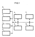
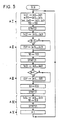
- FIG. 1 is a block diagram of part of an electronic circuit of an electronic machine to which the invention applies.
- the franking machine is of the type described in French patent application 87 02667, already cited; it includes a keyboard 1, a display 2, a calendar clock 3, a microprocessor 4, a program memory 5, a text memory 6, which is a ROM type ROM, a working memory 7 of RAM type, an alarm sound 8, connected by a bus B.
- the display is for example an alphanumeric display having a display capacity of L lines of N characters each, for example 2 lines of 16 characters.
- the text memory 6 contains a first set of messages for normal franking operators and a second set of messages for particular operations accessible by a menu key M on the keyboard.
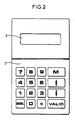
- FIG. 2 represents a keyboard display assembly equipping the machine; keyboard 1 has 10 numeric keys, a menu key M, a CANCEL cancellation key, a star key *, a VALID validation key and two scroll keys, one arrow up, the other arrow down, i.e. 16 keys total.
- the messages are displayed on display 2; for this the program memory 5 contains as many programs as there are messages, each program being relative to a message.
- the messages are divided into screens each having a number L of lines of N characters equal to the number L of lines of N characters that the display can visualize.
- An alphanumeric display allows you to view all the characters appearing in the ASCII code, also known as CCITT code No. 5.
- Each screen of a message is transferred, by the program relating to said message, from the text memory 6 to a memory space of the working memory 7, this space being called display image IA and having NL bytes, each byte being assigned to a character of a line.
- the display is carried out using a display program which is a specific program, contained in the program memory 5, which runs automatically every 100 milliseconds.
- This specific program is used to take the information from the bytes of the display image IA and transfer them to display 2 for viewing.
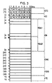
- FIG. 3 represents a part of the content of the working memory 7, this part comprising: - two bytes ITC0 and ITC1 for a temporary ITC keyboard image, - two bytes IC0 and IC1 for a keyboard image IC.
- the numbers, letters and signs are those of the 16 keys on the keyboard, M denoting the menu, V confirming and Canceling, each key corresponding to 1 bit of the bytes.
- thirty-two bytes IA0 to IA31 for the display image IA the bytes IA0 to IA15 being reserved for the first line EiL1 of a screen Ei, the bytes IA16 to IA31 being reserved for the second line EiL2 of the screen Ei, this of course in the case of a display of two lines of sixteen characters, - six bytes IHC0 to ICH5 for a clock, calendar image;
- the IHC0 byte is reserved for the year from 0 to 99;
- the IHC1 byte is reserved for the months 1 to 12;
- the IHC2 byte is reserved for the day from 1 to 31;
- the IHC3 byte is reserved for the hour, from 0 to 23;
- the IHC4 byte is reserved per minute, from 0 to 59;
- the IHC5 byte is reserved for
- a specific keyboard acquisition program which runs automatically every 20 milliseconds, is used to take the state of the keys on the keyboard and store them in the temporary ITC keyboard image; if this state does not change for at least 50 milliseconds, the image temporary keyboard is transferred to the keyboard image IC.
- a specific date and time acquisition program which runs automatically every 100 milliseconds, is used to take the content of six counters constituting the calendar clock (year, month, day, hour, minute and second) and transfer it to the IHC clock / calendar image.
- a specific audible alarm control program which runs automatically every 20 millseconds, is used to take the information contained in the three bytes of the CAS audible alarm control image and to transfer it to the audible alarm. 8 of the machine. These bytes are loaded by each program relating to a message, the audible alarm consisting of audible beeps. After each beep emitted, the first byte CAS0 is decremented by one.
- a specific timer program which runs automatically every 20 milliseconds, is used for the timers. It consists of doing -1 in the timer byte TE0 if the content of this byte is not zero, then starting again on the timer byte TE1.
- the second and third bytes of the audible alarm control CAS and the delay bytes TE0 and TE1 are loaded by a number; this number multiplied by the cycle time of the specific program gives the desired time; for example for a screen delay of 1 second, the number 50 is loaded into the TE0 delay byte.
- the working memory backed up by a battery, also contains the auxiliary counters in a reserved memory space, hereinafter referred to as the Counter space.
- the Counter space a reserved memory space
- the invention relates in particular to a large number of auxiliary counters, several tens for example, each counter being designated no longer by its number, but by its name, the counters being arranged, in the Counters area, in alphabetical order of their title ( name) which consists of alphanumeric characters.
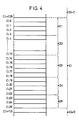
- FIG. 4 represents the occupation, in the Counter space, of a auxiliary counter Ci of the invention.
- a service area, Z1 of 4 bytes, the use of which will be specified below
- - a zone entitled, Z2 10 bytes reserved for storing the name, each byte containing a character part of the columns 3, 4 and 5 of the ASCII code (CCITT No. 5); the characters in these columns have a code between the hexadecimal values 30 and 5A which include: the 10 digits, 0 to 9, the signs; greater than, equal, less than, question mark, a round, and the 26 letters of the alphabet, - a 5 byte date and time zone for resetting the auxiliary counter, Z3.
- the information in this area is binary coded, and the 5 bytes contain, in order year, 0 to 99 (AA) the month, from 1 to 12 (MM) during the day, from 1 to 31 (DD) the hour, from 0 to 23 (HH) per minute, from 0 to 59 (mm) - an area for accumulating postage values, Z4, of 4 bytes.
- This area is a cash counter with a maximum capacity of 42,949,672.96 francs; it corresponds to a 32-bit binary counter, - an area for accumulating the number of frankings, Z5, of 3 bytes.
- This zone is a fold counter with a maximum capacity of 16,777,215 folds; it corresponds to a 24-bit counter.
- each auxiliary counter which and a double counter, occupies a memory space of 26 bytes, in the example described above; one could obviously have a zone of title Z2 of less than 10 bytes, or even of 16 bytes to use the display capacity of a line of the display in the case of a line with 16 characters.
- the number of bytes in area Z2 is defined by the manufacturer of the franking machine; the number of 10 bytes is therefore a value taken by way of example, this value appearing sufficient to allow a counter to be identified by its title.
- the bytes of an auxiliary counter Ci are identified by Cio, Ci1, ... Ci 25.
- the bytes Ci0 to Ci 3 are those of the service area Z1
- the bytes Ci4 to Ci13 are those of the title area Z2
- the bytes Ci14 to Ci18 are those of the date and time zone of reset Z3
- the bytes Ci 19 to Ci 22 are those of the cash counter zone Z4
- the bytes Ci 23 to Ci 25 are those of the Z5 fold counter area.
- the reset of an auxiliary counter Ci is carried out by loading 0 in the 7 bytes Ci 19 to Ci 25.
- the date and time of this reset are recorded in the 5 bytes Ci 14 to Ci 18; this is obtained by transferring the first five bytes of the clock / calendar image into bytes Ci 14 to Ci 18 of the auxiliary counter Ci.
- the date and time recorded make it possible to specify the duration of operation of the auxiliary counter; the time separating two resets defines the periodicity of the counter, this periodicity being determined by the user according to his needs.
- the auxiliary counters are arranged in alphabetical order by their titles.
- auxiliary counters being, according to the invention, designated by their title and no longer by their number, pressing the key 2 when viewing the message MP0 brings up the message MP 20.
- This message consists of the following four screens:
- Screens 1 to 4 are displayed for 3, 1, 1, 1 seconds respectively.
- the number of the counter appearing on screen 1 corresponds to the rank occupied by counter in the Counter space; three characters are assigned to the number of a counter. This number, for the same counter title, may vary depending on the creations and deletions. Thus, if the DURAND counter bears the number 22 at a given instant, it will have the number 23 following the creation of the DUPONT counter which precedes, in alphabetical order, the DURAND counter, the DUPONT counter then having number 22.
- a short press on the 1 key increments the counter number in screen 1 by 1 and brings up the name of the next counter. Following this action, the message MP 21 is reset and the screen 1 appears for 3 seconds.
- the operator keeps the key 1 pressed for more than a second, he triggers the accelerated advance, obtained by the program relating to the message MP 21 which then simulates short, increasingly rapid presses of the key 1.
- the program relating to the message MP 21 which then simulates short, increasingly rapid presses of the key 1.
- the title of the next counter appears one second, then the next one appears after 0.9 seconds, then the next one appears after 0.8 seconds, and so on, up to 0.3 seconds.
- Key 2 has the same function as key 1, but exploration of the Counter space is done in reverse.
- the text of the message MP 21, like all the messages, is stored in the text memory 6 of the franking machine.
- the programs relating to the messages MP 21 to MP 23 use a memory space "Search" of seven bytes, from the working memory 7, these successive bytes being arranged starting from the symbolic address Search 0 which is that of the first byte.
- an initialization program determines the number n of counters present in the counter space, n being less than or equal to Q which is the maximum number of counters that the space can contain Counters.
- the first 32 bytes of the message MP 21 (screen 1) from the text memory into the display image IA of the working memory, from the address IA0, which is that of the first byte of this display image.
- the first 32 bytes of the MP 21 message correspond to a 2-line display of 16 characters, taken as an example. Take m, number of the counter, in R1 and put it away, after processing (change to decimal then to ASCII code), in the display image IA at addresses IA12, I13 and IA14 (three digits maximum).
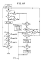
- the SPMP 21 subroutine shown in FIGS. 6A and 6B carries out the following actions, designated by SP1, SP2, ... etc.
- This action is the initialization phase for pressing keys 1 or 2 (see SP1).
- Load 1 second (50) into R4 which is the memory byte of the acceleration delay (MT).
- This action is the phase of decrease of the display time of the names of the counters (see SP1).
- Action SP 13 selection of the next or previous counter.
- n the number of existing counters
- This message appears following an action on the key 3 when viewing the message MP21.
- the message MP22 includes the following eight screens:
- Screens 1 to 8 are displayed for 2, 1, 3, 2, 2, 2, 2 seconds, respectively.
- the counter number, line 1, and its title (name), line 2 are those that were displayed in screen 1 of the message MP21 when the operator chose option "3 - The to consult".
- the counter number is contained in byte R1
- its title is contained in the 10 bytes Ci4 to Ci13 of the zone Z2 of the counter, the starting address AC + 4 of Ci4 in the Counter space being given by the content, AC, of R2 and R3, to which we add 4. This is identical to what is indicated in action 1 of the message MP21.
- the date and time, line 2 of screen 2 are those of the last reset, and are contained in the 5 bytes of zone Z3 of the counter, from address AC + 14, AC being given by the content of R2 and R3 to which 14 is added.
- the two pieces of information on screen 4 are extracted from the zone Z4 of the counter on line 1, and from the zone Z5 of the counter for line 2.
- zone Z4 of the counter If the cumulative cash, zone Z4 of the counter, and the cumulative number of folds, zone Z5 of the counter, are at zero, the proposition "3 - Reset, from screen 6 does not appear; it is replaced, in bytes IA16 to IA31 of the display image, with space symbols.
- Propositions 4 and 5 of screen 7 are mutually exclusive; only the inverse proposition of the state of the counter displayed appears.
- the first service byte, zone Z1 of the meter contains the letter M, the proposition "4 - Stop it” appears, but not the proposition "5 - Start it”;
- the first service byte contains the letter A, the proposition "4 - Stop it” does not appear, but the proposition "5 - The Start” appears.
- This message consists of the following 3 screens:
- the text of the second line of screen 1 is: a reset (key 3) a stop (key 4) starting (key 5) deletion (key 6)
- the text of the second line of screen 2 consists of the title of the counter, which is the same as that which appeared on the second line of screen 1 of the message MP22 when the operator pressed one of the keys 3, 4, 5 or 6.
- Pressing the cancel key also returns to the message MP22, but without executing the order.
- the letter A (code 41 in hexadecimal) is loaded in the first service byte of the counter, with address AC. From this moment the counter no longer accumulates cash or folds.
- the letter M (code 4D in hexadecimal) is loaded in place of the letter A in the first service byte of the counter which then accumulates cash and folds.
- the following program runs: Read the otect of address AC + 26 and write it to the address AC; the byte of address AC + 26 is the first service byte of the following counter, Read the byte of address AC + 27 and write it to the address AC + 1, and so on by increasing each time the read address and the write address, until the transfer of the last byte of the last counter, that is to say when the read address has become equal to C10 + 26n-1, the address C10 being that of the first byte of the Counter space in the working memory, the write address then being equal to C10 + 26 (n-1) -1.
- the creation of a counter consists of composing its title, then the name being validated, to find the place it must occupy in the Counter space.
- the Counter space contains the DUPONT and DURAND counters, and a DUPUIS counter is created, this must be stored between the DUPONT and DURAND counters, to observe the alphabetical order. This is obtained by shifting all the counters located after the DUPONT counter by one position (this operation is identical to deleting, but performed in reverse) and inserting the DUPUIS counter. Of course, you can only create a new counter if n is less than Q.
- the search for the place of the new counter whose name has just been composed, the shifting of the counters and the loading of the bytes of the new counter are carried out using a storage program which takes place when the name has been composed .
- the first counter to be shifted must be searched for; for this the storage program uses the well-known method of dichotomous research.
- the last byte of the last counter n used with address C10 + 26n-1 in the Counter space, is read and written at the address C10 + 26 (n + 1) -1 which is that of the last byte of counter n + 1 , and so on by doing -1 in the read and write addresses until the read address is equal to the AC address of the first byte of the first counter to be shifted, which ends the shift of counters.
- the display times of screens 1 to 5 are 3, 1, 1, 1, 1 seconds respectively.
- the name of a counter can have a maximum of 10 characters, since it has been assumed that the counter title area Z2 has 10 bytes (one per character).
- the frame rate is 1 character every 0.8 seconds. when the letter Z appears, the next character is the number 0, so the sequence of admissible characters is completed, and the appearance of the number 0 causes the emission of a beep to signal to the operator the start of a character scrolling cycle.
- a fleeting action on key 1 immediately brings up the next character; following this action the message MP25 is reset, the scrolling of characters is suspended, and screen 1 is displayed for 3 seconds.
- Key 2 has the same function as key 1, but causes the characters to scroll in reverse order.
- Pressing key 3 validates the displayed character and initiates the scrolling of characters to the position immediately to the right of the validated character. If the validated character is the tenth of the name, the scrolling does not appear on the next position, this one being off screen.
- the key 4 allows to return to the previous position with erasure of the position which has just been left.
- Key 5 is used by the operator to indicate to the franking machine the end of the composition of the name.
- the procedure for storing the new meter among the meters existing ones is then engaged, this procedure starting, as indicated above, by the search for the first counter to shift.
- the implementation of the program relating to the message MP25 uses a "Title" zone of 15 bytes of the working memory whose symbolic addresses are INT0 to INT14. We find in order, at the different addresses: INT0 to INT9: Ten bytes assigned to the name of the counter being created, INT 10: reserve byte, INT 11: position in the name of the character being created, INT 12: memory of the scroll delay, INT 13: key phase INT 14: automatic scrolling authorized or not.
- the MP25 message program performs actions, some of which use a SPMP25 subroutine from the MP25 message program.
- FIG. 7 The flowchart of the program relating to the message MP25 is shown in FIG. 7, and the flowchart of the sub-program SPMP25 is shown in FIGS. 8A and 8B.
- the program relating to the MP25 message includes the following actions:
- Action 1 Initialization of the composition of the name.
- Action 5 Display of the screen 3.
- Action 7 Display of the screen 5.
- the SPMP25 subroutine is used to check the flow of the screen delay, TE0 byte, and to manage the actions on keys 1, 2, 3, 4, 5 and cancellation; it follows the following actions, designated by SP1, SP2, ...:
- the corresponding bit in the IC keyboard image has the value o, wait for the operator to release it, i.e. the value of the corresponding bit in the IC keyboard image changes to 1, then: if the content of the address byte INT11 is less than 10, add 1 to this content and return to action 2 of the program, otherwise, return to action 2, without modifying the content of the byte of INT11 address. If key 3 is not pressed go to action SP3.
- Cancel key is pressed, return to the message MP20, it is the abandonment of the creation of a counter; end of program for message MP25. If the cancel key is not pressed and if the menu key is pressed return to the message MP0. If the menu key is not pressed go to action SP6.
- Action SP10 Initialization of pressing keys 1 and 2.
- Action SP12 Waiting for the scrolling time to elapse.
- auxiliary counters can be running simultaneously; at the limit, all the counters in the Counters area can be running.
- the value of the stamp which has just been issued must be added to each of the cash counters (zone Z4 of each auxiliary counter) and the number of folds of each fold counter (zone Z5 of each auxiliary counter), must be increased by one unit. This operation can be relatively long, and while it is being carried out, it is necessary to prohibit the production of the next franking, which reduces the performance of the franking machine.
- the procedure chosen consists in realigning the auxiliary meters in operation, no longer after each franking, but at privileged times.
- the time separating two privileged moments constitutes the realignment period.
- the method consists in accumulating the total of postage in a counter "Consumption period" of 4 bytes in the working memory, and to add 1, after each postage, in a counter of "Period folds" and 3 bytes in the working memory .
- a realignment program examines the first byte Cio of each auxiliary counter. If the content of this byte is the letter A (stop) the program goes to the next auxiliary counter.
- the program adds the content of the counter "Period consumption” to the content of the cash counter of the auxiliary counter, and it adds the content of the counter "Period folds” to the fold counter of this same auxiliary counter, then the realignment program examines the next auxiliary counter. When the last auxiliary counter in operation is realigned, the program resets the "Period consumption” and "Period folds" counters. The realignments are carried out: When switching on the franking machine; these are the accumulations of postage which took place before the power cut, When the message MP20 "Search or create a counter" appears. At the appearance of the message MP22 consultation of a counter, following a confirmation of a request to shutdown (message MP23).
- An auxiliary counter can have one or more sub-counters (notion of total and subtotal).
- a counter becomes under counter if its title is that of an auxiliary counter to which we add the @ sign (a circle) followed, possibly, by a text, numbers or letters.
- the operator creates a first "Store” counter, then a second "Store @ 1" counter; this second counter is a sub-counter of the first.
- the second service byte, Ci1 of each counter is used, this byte contains the letter C for a counter (absence of @ in its title) and the letter S for a sub-counter (presence of the @ sign in its title).
- a sub-counter can be deleted independently of the other sub-counters of the same counter, but the deletion of a counter automatically deletes all the sub-counters which are attached to it.
- each sub-counter of a counter can be zeroed independently of the others, but resetting a counter automatically causes all of its sub-counters to be reset to zero.
- Switching on or off a counter automatically switches on or off the sub-meters attached to it.
- a sub-counter cannot be switched on or off independently of the counter to which it is attached.
- FIGS 5, 6A, 6B, 7, 8A and 8B are flow charts, as indicated above.
- FIGS. 6A, 6B, 8A, 8B the numbers 1, 2, ..., the letters, A, M, V which appear in the diamonds designate the numeric keys, cancel (A), menu (M), validation (V).
- the number 1 means yes, and the number 0 means no.
- the reference DEB means start of the program, or of the sub-program.
- references AI, AII, etc. denote the actions of the corresponding program.
- the reference PR means program for storing the counter in the Counter space.
Applications Claiming Priority (2)
| Application Number | Priority Date | Filing Date | Title |
|---|---|---|---|
| FR8704577A FR2613513B1 (fr) | 1987-04-01 | 1987-04-01 | Machine a affranchir electronique comportant un grand nombre de compteurs auxiliaires |
| FR8704577 | 1987-04-01 |
Publications (1)
| Publication Number | Publication Date |
|---|---|
| EP0285997A1 true EP0285997A1 (de) | 1988-10-12 |
Family
ID=9349676
Family Applications (1)
| Application Number | Title | Priority Date | Filing Date |
|---|---|---|---|
| EP88105168A Ceased EP0285997A1 (de) | 1987-04-01 | 1988-03-30 | Elektronische Frankiermaschine mit einer grossen Anzahl von Hilfszählern |
Country Status (3)
| Country | Link |
|---|---|
| US (1) | US4914606A (de) |
| EP (1) | EP0285997A1 (de) |
| FR (1) | FR2613513B1 (de) |
Families Citing this family (10)
| Publication number | Priority date | Publication date | Assignee | Title |
|---|---|---|---|---|
| DE4302097A1 (de) * | 1993-01-20 | 1994-07-21 | Francotyp Postalia Gmbh | Anordnung zur Erzeugung eines jeweils einer Kostenstelle zugeordneten Frankierbildes |
| US5490077A (en) * | 1993-01-20 | 1996-02-06 | Francotyp-Postalia Gmbh | Method for data input into a postage meter machine, arrangement for franking postal matter and for producing an advert mark respectively allocated to a cost allocation account |
| EP0658861B1 (de) * | 1993-12-16 | 1998-09-23 | Francotyp-Postalia Aktiengesellschaft & Co. | Verfahren zum Betreiben einer Frankiermaschine |
| US7035832B1 (en) * | 1994-01-03 | 2006-04-25 | Stamps.Com Inc. | System and method for automatically providing shipping/transportation fees |
| US5572429A (en) * | 1994-12-05 | 1996-11-05 | Hunter; Kevin D. | System for recording the initialization and re-initialization of an electronic postage meter |
| US5717596A (en) * | 1995-02-15 | 1998-02-10 | Pitney Bowes Inc. | Method and system for franking, accounting, and billing of mail services |
| US5689424A (en) * | 1996-08-23 | 1997-11-18 | Pitney Bowes Inc. | Encoded screen records for international postage meters |
| US6820065B1 (en) | 1998-03-18 | 2004-11-16 | Ascom Hasler Mailing Systems Inc. | System and method for management of postage meter licenses |
| EP1064621B1 (de) * | 1998-03-18 | 2006-08-02 | Ascom Hasler Mailing Systems, Inc. | System und verfahren zur verwaltung von frankiermaschinenlizenzen |
| US8624934B2 (en) * | 2011-09-29 | 2014-01-07 | Microsoft Corporation | Dynamic display of icons on a small screen |
Citations (7)
| Publication number | Priority date | Publication date | Assignee | Title |
|---|---|---|---|---|
| GB947991A (en) * | 1962-10-09 | 1964-01-29 | Luther George Simjian | Dispensing system |
| US4093999A (en) * | 1976-12-01 | 1978-06-06 | Vickers Limited | Electronic franking machines |
| GB2032224A (en) * | 1978-07-21 | 1980-04-30 | Post Office | Improvements in or Relating to Franking Machines |
| US4319328A (en) * | 1980-02-27 | 1982-03-09 | Sabre Products, Inc. | Postage cost recording system |
| US4511793A (en) * | 1983-04-04 | 1985-04-16 | Sylvester Racanelli | Mail metering process and machine |
| US4577283A (en) * | 1982-12-08 | 1986-03-18 | Pitney Bowes Inc. | Postage meter with keyboard keys for causing meter operations to be performed |
| DE3517087A1 (de) * | 1985-05-11 | 1986-11-13 | Neumann Elektronik GmbH, 4330 Mülheim | Verfahren zur vergroesserung der maximalanzahl moeglicher programmier-loesch-zyklen an einem elektrisch programmierbaren und loeschbaren festwertspeicher (eeprom) sowie einrichtung zur durchfuehrung des verfahrens |
Family Cites Families (8)
| Publication number | Priority date | Publication date | Assignee | Title |
|---|---|---|---|---|
| US4306299A (en) * | 1976-06-10 | 1981-12-15 | Pitney-Bowes, Inc. | Postage meter having means transferring data from a working memory to a non-volatile memory under low power conditions |
| US4271481A (en) * | 1976-06-10 | 1981-06-02 | Pitney Bowes Inc. | Micro computerized electronic postage meter system |
| US4180856A (en) * | 1977-07-29 | 1979-12-25 | Pitney Bowes Inc. | Electronic postage metering system |
| US4376981A (en) * | 1978-06-26 | 1983-03-15 | Pitney Bowes Inc. | Electronic postage metering system |
| US4484307A (en) * | 1979-05-09 | 1984-11-20 | F.M.E. Corporation | Electronic postage meter having improved security and fault tolerance features |
| US4524426A (en) * | 1983-04-19 | 1985-06-18 | Pitney Bowes Inc. | Electronic postage meter controllable by mailing machine |
| JPS62105202A (ja) * | 1985-10-31 | 1987-05-15 | Fanuc Ltd | Ncデ−タ作成方法 |
| US4823283A (en) * | 1986-10-14 | 1989-04-18 | Tektronix, Inc. | Status driven menu system |
-
1987
- 1987-04-01 FR FR8704577A patent/FR2613513B1/fr not_active Expired
-
1988
- 1988-03-30 EP EP88105168A patent/EP0285997A1/de not_active Ceased
- 1988-04-01 US US07/176,521 patent/US4914606A/en not_active Expired - Lifetime
Patent Citations (7)
| Publication number | Priority date | Publication date | Assignee | Title |
|---|---|---|---|---|
| GB947991A (en) * | 1962-10-09 | 1964-01-29 | Luther George Simjian | Dispensing system |
| US4093999A (en) * | 1976-12-01 | 1978-06-06 | Vickers Limited | Electronic franking machines |
| GB2032224A (en) * | 1978-07-21 | 1980-04-30 | Post Office | Improvements in or Relating to Franking Machines |
| US4319328A (en) * | 1980-02-27 | 1982-03-09 | Sabre Products, Inc. | Postage cost recording system |
| US4577283A (en) * | 1982-12-08 | 1986-03-18 | Pitney Bowes Inc. | Postage meter with keyboard keys for causing meter operations to be performed |
| US4511793A (en) * | 1983-04-04 | 1985-04-16 | Sylvester Racanelli | Mail metering process and machine |
| DE3517087A1 (de) * | 1985-05-11 | 1986-11-13 | Neumann Elektronik GmbH, 4330 Mülheim | Verfahren zur vergroesserung der maximalanzahl moeglicher programmier-loesch-zyklen an einem elektrisch programmierbaren und loeschbaren festwertspeicher (eeprom) sowie einrichtung zur durchfuehrung des verfahrens |
Also Published As
| Publication number | Publication date |
|---|---|
| FR2613513A1 (fr) | 1988-10-07 |
| US4914606A (en) | 1990-04-03 |
| FR2613513B1 (fr) | 1989-06-23 |
Similar Documents
| Publication | Publication Date | Title |
|---|---|---|
| EP0285956B1 (de) | Frankiermaschine mit Verwaltung periodischer Abläufe | |
| EP0281862B1 (de) | Betriebssystem für eine elektronische Frankiermaschine | |
| US20010007980A1 (en) | Electronic book system and its contents display method | |
| US6073090A (en) | System and method for independently configuring international location and language | |
| FR2753088A1 (fr) | Procede de mise en oeuvre d'un pilulier electronique de poche a compartiments multiples et dispositif de redaction d'ordonnance utilise dans le procede | |
| EP0285997A1 (de) | Elektronische Frankiermaschine mit einer grossen Anzahl von Hilfszählern | |
| US20070011624A1 (en) | Task navigator including a user based navigation interface | |
| FR2647239A1 (fr) | Procede de generation d'interfaces pour applications-utilisateurs visualisables sur l'ecran d'un systeme informatique et dispositif pour mettre en oeuvre ledit procede | |
| EP0893761A1 (de) | Vorrichtung und Verfahren zur dynamischen Regelung der Betriebsmittelzuweisung in einem Computersystem | |
| EP0018889A1 (de) | Verfahren zur Verlängerung der Gültigkeit der Arbeitszone des Speichers eines Datenträgers | |
| EP0281861B1 (de) | Elektronische Frankiermaschine mit Grenzwerten für die Frankierung | |
| EP0605313B1 (de) | Frankiermaschine mit Geschichtsabspeicherung | |
| EP0281860A1 (de) | Elektronische Frankiermaschine mit Auswahl der Betriebsart | |
| CN109584392A (zh) | 信息输出方法、装置及电子设备 | |
| US20050149855A1 (en) | Graphical scratchpad | |
| US20030132952A1 (en) | Jukebox user interface | |
| EP0284779A1 (de) | Mit einem Alarm ausgestattete Frankiermaschine | |
| FR2553549A1 (fr) | Machine de parking automatique | |
| JP3929824B2 (ja) | 会計処理装置および自動仕訳プログラムを記録したコンピュータ読み取り可能な記憶媒体 | |
| BE1015630A6 (fr) | Carte binaire de paiement internet et les cinq systemes modulables. | |
| AU5659099A (en) | Function key for computer data handling | |
| JP2003346072A (ja) | 記帳システム、摘要辞書編集画面、摘要登録方法、摘要辞書編集方法、プログラム及び記憶媒体 | |
| FR2534394A1 (fr) | Repertoire electronique de poche | |
| JPH10312372A (ja) | 月日に他の情報を付加する方法 | |
| JPH10154153A (ja) | 提供情報を画面に検索表示する自動機 |
Legal Events
| Date | Code | Title | Description |
|---|---|---|---|
| PUAI | Public reference made under article 153(3) epc to a published international application that has entered the european phase |
Free format text: ORIGINAL CODE: 0009012 |
|
| AK | Designated contracting states |
Kind code of ref document: A1 Designated state(s): DE FR GB |
|
| 17P | Request for examination filed |
Effective date: 19890411 |
|
| RAP1 | Party data changed (applicant data changed or rights of an application transferred) |
Owner name: ALCATEL SATMAM |
|
| 17Q | First examination report despatched |
Effective date: 19911212 |
|
| STAA | Information on the status of an ep patent application or granted ep patent |
Free format text: STATUS: THE APPLICATION HAS BEEN REFUSED |
|
| RAP1 | Party data changed (applicant data changed or rights of an application transferred) |
Owner name: NEOPOST INDUSTRIE |
|
| 18R | Application refused |
Effective date: 19921220 |