EP0285584A2 - A post structure - Google Patents
A post structure Download PDFInfo
- Publication number
- EP0285584A2 EP0285584A2 EP88850089A EP88850089A EP0285584A2 EP 0285584 A2 EP0285584 A2 EP 0285584A2 EP 88850089 A EP88850089 A EP 88850089A EP 88850089 A EP88850089 A EP 88850089A EP 0285584 A2 EP0285584 A2 EP 0285584A2
- Authority
- EP
- European Patent Office
- Prior art keywords
- post
- section
- sections
- ground
- construction according
- Prior art date
- Legal status (The legal status is an assumption and is not a legal conclusion. Google has not performed a legal analysis and makes no representation as to the accuracy of the status listed.)
- Granted
Links
Images
Classifications
-
- E—FIXED CONSTRUCTIONS
- E04—BUILDING
- E04H—BUILDINGS OR LIKE STRUCTURES FOR PARTICULAR PURPOSES; SWIMMING OR SPLASH BATHS OR POOLS; MASTS; FENCING; TENTS OR CANOPIES, IN GENERAL
- E04H12/00—Towers; Masts or poles; Chimney stacks; Water-towers; Methods of erecting such structures
- E04H12/02—Structures made of specified materials
- E04H12/08—Structures made of specified materials of metal
Definitions
- the present invention relates to a post or mast structure which is intended to support a load above ground level, preferably an elongated load.
- This load may represent an object which is supported by a plurality of mutually co-acting posts, such as an overhead power cable, or an elongated object which is supported solely by a single post and which projects outwardly on one side thereof, or which projects in balance from both sides of the post.
- Posts, or masts are to be found in many different forms and for many different purposes, ranging from lattice-work mast structures for carrying 400 kV overhead power-cables down to fencing posts of 50 mm diameter.
- the posts may be grouted in the ground or simply secured by burying one end of the post in a pit or hole formed in the ground and by compacting natural stone around the post, so as to hold the post firm.
- Flag posts and sign posts can be said to constitute particular examples of the posts referred to here.
- creosote tar a creosote tar
- creosote tar a creosote tar
- Another drawback with creosote-impregnated posts is that they may not be stored in the open air, due to the fact that the impregnation methods used result in moist posts, caused by incomplete absorption of the creosote tar and manifested in sticky wood surfaces.
- Arsenic-copper salt solutions are alternative impregnating agents to creosote tar, but since these solutions have a shorter effective life span than creosote they are not as economically viable.
- Arsenic-copper salt solutions are alternative impregnating agents to creosote tar, but since these solutions have a shorter effective life span than creosote they are not as economically viable.
- Overhead power cables intended for more than 70 kV are supported by lattice-work posts or masts.
- such masts are highly unaesthetic and present an ugly feature in the surrounding landscapes.
- the need for power lines is increasing with the increasing need for electrical energy from Progressivesively increasing production units to progressively higher consumer concentrations. In many areas or districts, this has resulted in a multiple of power cables or lines being erected in parallel.
- the posts or masts involved herewith detract greatly from the surrounding countryside and, in addition, present obstacles to agricultural machines working in the area. The same applies to posts used to carry telecommunication lines, although in this case the posts are not as high as the masts used to carry power cables and are not therefore equally as discernible to the eye.
- the method used hitherto for erecting wooden posts for different purposes is one in which a pit is dug to a prescribed depth, in the case of posts for carrying 10 kV cables a depth of 1.40 m, whereafter the root-end of the post is placed in the pit and the post lifted to a vertical position. The pit, or hole, is then fitted with available screened aggregate and the post is brought to a truly vertical position prior to filling in the pit and finally consolidating the packing material.
- the work of preparing post pits has been facilitated for many years by the use of earth drills and tractor-carried vertical diggers. However, the ground surrounding the pits is often uneven or is inclined, which results at times in incomplete compaction of the aggregate intended to anchor the posts.
- the object of the present invention is to provide a post or like structure which when dimensioned for its intended function is able to carry the load involved, irrespective of whether this load is represented by a road safety-fence which extends less than one metre above road level or by a high-tension cable supported at a height of more than 20 metres above ground level.
- This object is achieved with a post that has the characteristic features set forth in the following claims.
- one important feature of the inventive post is that no pit or hole is required. Instead a first section of the post, which forms a post foundation, is hammered or likewise driven into the ground.
- the posts In the case of posts which are 50 mm in diameter, the posts may be continuous, single-piece structures and are driven into the ground to a depth of about 50 cm. In the case of posts which are intended to support overhead power cables and which are to be erected on marshy ground, this first post section may not be long enough to achieve firm frictional engagement with the surrounding soil or earth, and consequently it will be necessary to drive a further post section into the ground in order to achieve the requisite degree of friction. This thus obviates the need of pile driving to refusal.
- Shorter posts may be driven into the ground with the aid of hydraulically operated drivers.
- the aforesaid first post section can be driven into the ground with the aid of a tractor-carried, pneumatic or hydraulic high-speed hammer. It has been found in practice that this method can be applied also with frozen ground, and that the first post section can be driven into such ground in a matter of only some few minutes.
- the various post sections of a multi-section post are of tubular configuration and provided with a socket coupling at one end and a conically tapered spike at the other, the sections can be readily assembled to form a continuous post.
- the conicity of the tapered spiked end of respective post sections is preferably such that the joint effected between two mutually adjacent post sections is self-locking, such that the post will withstand relatively large loads, more specifically both the load exerted axially by the object carried by the post and also the bending stresses created, e.g., at the juncture where a change in cable direction is made.
- the post sections are also preferably made of ductile iron, therewith to improve the flexural strength of the post still further.
- Ductile iron is relatively resistant to corrosion, and by coating the hollow tubular posts with asphalt, both internally and externally, to a thickness of at least 50 microns in accordance with one preferred embodiment of the invention, the posts can be given a useful active life of more than 100 years.
- the post section which, in accordance with the invention, is driven into the ground can be used as a foundation for other types of post.
- that part of the post which extends above ground level may consist of a continuously tapering, or step-wise tapering galvanized steel tube.
- Wooden posts may also be fitted to the ground-located first post section.
- there is no restriction to posts of round cross-section since it suffices that the connecting end of the overlying post section has a configuration which conforms to the configuration of the socket connector of the ground-located post section.
- an advantage is afforded when the ground-located first post section is fitted with a post shoe prior to being driven into the ground, the size of the post shoe used being dependent on the nature of the ground into which said post part is driven.
- the function of the post shoe is to form in the ground a hole whose cross-dimension is greater than the cross-dimention of the ground-located post section. This hole enables an erected post to be aligned truly with the vertical, where after the hole can be filled with loose aggregate in the vicinity of the ground-located post section. This will further reduce the risk of corrosion.
- the ground located part of the post may also be provided with preferably axially extending elongated slots. Subsequent to having driven the ground-located post section to the intended ground depth, concrete is pumped thereinto and exits through the slots. When a sufficiently large post shoe is used, the ground-located post section will be surrounded by concrete, thus creating a firm foundation.
- Ductile iron such as nodular iron
- the above-ground post sections can therewith readily be given a configuration which tapers towards the spiked ends of respective sections. Since the ground-located post section is normally driven into the ground with its spiked end facing downwards, the connecting socket of this post section is fitted with an auxiliary, transition post section which is spiked at both ends. This enables the above-ground sections of a multiple section post assembly to be assembled with the connecting sockets facing downwards.
- the auxiliary post part may comprise a multiple of very short post sections which are used between two mutually adjacent above-ground post sections for dimension changing purposes. This enables very high post constructions to be given a diameter which decreases with each further post section above ground level - normally with each five metres of post length.
- the post Since the post is of hollow tubular construction, the upper end of the post will be open. It is therefore preferred to fit to the end of the top post section a cap or like cover member, preferably a capping sleeve.
- the capping sleeve is made of the same material as the post, since materials of mutually different electro-potential are liable to induce corrosion in the magnetic field surrounding the conductors, particularly in the presence of rain water and a contaminated atmosphere.
- inventive posts When inventive posts are used in groups of twos or threes, for example to support high-tension cables and larger ski-lifts, it is necessary to connect together with tops of respective posts or masts with the aid of connecting elements.
- These elements may consist of lengths of conventional angle iron secured to respective posts with the aid of conventional fasteners, such as nuts and bolts.
- the connecting elements or attachment devices therefore may also be welded to respective iron parts.
- An alternative solution is to place over the tops of respective posts a tubular post section which lacks the provision of connecting sockets and has a larger diameter than the tops of said posts and which is provided with two apertured recesses at a mutual distance apart equal to the distance between the tops of the posts.
- This hollow tubular connecting element may, of course, be secured to respective posts with the aid of suitable fasteners.
- the apertured recesses may be given the same configuration as the top ends of the post, so as to engender a self-locking effect. It will be understood that if the posts are inclined towards one another, the apertures must be formed at an angle of less than 90° to the longitudinal axis of the connecting element.
- the surfaces of the posts will normally be treated with an asphalt emulsion, although they may alternatively be painted in any desired colour.
- the illustrated post construction includes a tubular post section 1 which is intended to be driven into the ground such as to provide a post foundation therein and to which there is fitted a pole shoe 2.
- One end 3 of the foundation-forming post section 1 is spiked and the pole shoe is fitted to this spiked end by means of legs (not shown) which extend upwardly internally of said post section, or with the aid of a connecting socket which embraces said spiked end 3.
- the opposite end of the foundation forming post section 1 is provided with a conical connecting socket 4 into which there is inserted an auxiliary or bridging post section 5, the two ends of which have a spiked configuration which corresponds to the conicity of the socket 4.
- Fitted to the spiked end of the auxiliary post section 5 distal from the foundation-forming post section 1 is the connecting socket 7 of a first post section 6.
- the socket 7 on the first post section 6 has an internal conicity which coincides fully with the conicity of the upper spiked end of the auxiliary section 5.
- This conicity has a tapering ratio of at least 1:14 and at most 1:20, i.e. the diameter decreases one length unit in an axial direction over a maximum of 20 length units.
- a second, and optionally several post sections 8, 9 can be fitted consecutively above the first post section 6, the number of sections fitted being dependent on the desired height of the post assembly.
- the higher post sections 8, 9 may have a diameter which decreases in relation to the underlying post section 6.
- the adapters have the form of very short post sections, of which the conicity and dimension of the connecting socket coincide with the conicity and the dimension of the connecting socket 7 of the first post section 6, the adapter 10 being fitted to the spike end of said first post section.
- a further difference between a diameter-reducing adapter and a post section is that the spiked end of the adapter has a diameter which corresponds to the inner diameter of the connecting socket on the post section to be placed above the diameter-decreasing adapter.
- foundation-forming post sections 1, 1 ⁇ When erecting posts intended for supporting high-tension cables, it may be necessary to drive two or more foundation-forming post sections 1, 1 ⁇ into the ground.
- These foundation-forming post sections are configured in a similar manner to the overhead post sections, i.e. each have mutually corresponding connecting sockets 4 and spiked ends 3 with self-locking facilities.
- These foundation-forming sections can be driven straight into the ground to provide a stable foundation at a requisite depth so as to provide the necessary support, even in ground which would not otherwise be considered suitable for the erection of such posts or masts.
- the diameter-reducing adapters are placed approximately 10 metres apart, even though shorter post sections should be used.
- Tressel-like post configurations are used for supporting high-tension cables of 130 kV.
- the supporting tressels comprise two posts which extend vertically or are inclined one towards the other and which are interconnected at the top of respective sections by means of a horizontal connecting bridge 12, which may comprise either a single post section or a number of interfitted post sections.
- the post section or sections forming the connecting bridge 12 must have a larger diameter than the post sections forming the limbs of the tressel-like structure.
- the holes required in the connecting bridge 12 to enable the bridge to be fitted over the pointed ends of the uppermost post sections can be formed with the aid of a conical boring tool provided in the high-tension cable construction equipment and which has the same cutting angle as the spiked ends of respective post sections 9.
- the connecting bridge 12 can be anchored to the top post elements 9 with the aid of a vibrating device. Attachment devices for the insulators from which the high-tension cables are to be suspended are screwed firmly into the connecting bridge 12.
- the guy peg used to this end may comprise a foundation-forming post section 1, which may or may not be fitted with a driving shoe 2, or may comprise a post element of desired diameter which is driven into the ground at an acute angle to the surface thereof. Concrete is then poured into the hollow guy peg 13 and an eye bolt 14 is secured in the concrete.
- a guy wire 15 connected to the post at a suitable height thereon is then connected to the eye bolt 14 and tensioned.
- the eye bolt may comprise guy wire which is wound around the post section beneath the connecting socket, therewith eliminating the need of filling the post section with concrete.
- the foundation-forming post section 1 is driven into the ground in the aforedescribed manner.
- the connecting socket 17 of a lamp post 16 is fitted over the upper spiked end of the auxiliary section 5.
- the post 16 preferably tapers continuously upwards and may consists of a single-piece structure to a height of 5 metres.
- Fitted to the upper spiked end of the post 16 is a single arm or double-arm element 18 which carries a lamp 19 at the extremities of respective arms.
- the electric wires required for connecting-up the lamp or lamps can be readily drawn through the hollow post as the post is being erected.
- the foundation-forming post section is driven into the ground in the manner aforedescribed whereafter a post section 20 is fitted over the auxiliary post section 5.
- the post section 20 of this embodiment differs from the aforementioned post sections, in that the spiked end 21 of the post section 20 decreases in diameter stepwise at the location where its cone begins to converge.
- the post section 20 has fitted thereto an overlying post section 22 which is provided with a connecting socket whose outer diameter is equal to the outer diameter of the post sec tion 20.
- the post section 22 tapers upwards from the connecting socket to a given point on said section, whereafter the diameter of the section remains constant.
- a T-piece 23 Connected to the spiked end of the post section 22 is a T-piece 23, the vertical leg of which is configured as the connecting socket on one of the aforedescribed post sections.
- the horizontal part of the T-piece 23 has the form of a hollow sleeve of uniform diameter. Extending through the horizontal sleeve is a smooth iron tube which forms a crosspiece 24, which is secured to the T-piece 23 by means of a preferably conical locking pin which is driven into a hole drilled through the T-piece 23 and into the crosspiece 24.
- the crosspiece 24 is intended to support lamp fittings or power-cable insulators 25, which ever are required.
- the post sections In the majority of cases it is preferred to assemble the post sections on the ground.
- the post is assembled by placing the connecting socket 7 of the first post section 6 against a firm abutment, whereafter the diameter-reducing adapter 10 is fitted to the spiked end of the post section 6.
- the connecting socket of the second post section 8 is then fitted onto the adapter 10 and an annular vibrating device is placed around the connecting socket of the post section 8 and the parts are hammered together.
- a conical locking pin or like device can be driven into a hole drilled through each connecting socket and into the spiked end of a post section located in said socket. Assembly of the post is continued until the requisite number of post sections have been fitted together, whereafter the post is erected.
- the assembled post can be raised with the aid of a relatively powerful tractor-carried digger, even though the ground around the post has been highly compacted when driving in the foundation-forming section 1, which in itself contributes towards firming the post.
- the use of a tractor-carried digger affords a practical solution both when erecting a single post and when erecting a complete power-cable installation.
- posts constructed in accordance with the invention afford an economically advantageous alternative, particularly with regard to their re-usability.
Landscapes
- Engineering & Computer Science (AREA)
- Architecture (AREA)
- Life Sciences & Earth Sciences (AREA)
- Chemical & Material Sciences (AREA)
- Materials Engineering (AREA)
- Wood Science & Technology (AREA)
- Civil Engineering (AREA)
- Structural Engineering (AREA)
- Foundations (AREA)
- Pharmaceuticals Containing Other Organic And Inorganic Compounds (AREA)
- Pyridine Compounds (AREA)
- Acyclic And Carbocyclic Compounds In Medicinal Compositions (AREA)
- Devices For Conveying Motion By Means Of Endless Flexible Members (AREA)
- Saccharide Compounds (AREA)
- Hydrogenated Pyridines (AREA)
- Snaps, Bayonet Connections, Set Pins, And Snap Rings (AREA)
- Revetment (AREA)
- Steering Devices For Bicycles And Motorcycles (AREA)
Abstract
Description
- The present invention relates to a post or mast structure which is intended to support a load above ground level, preferably an elongated load. This load may represent an object which is supported by a plurality of mutually co-acting posts, such as an overhead power cable, or an elongated object which is supported solely by a single post and which projects outwardly on one side thereof, or which projects in balance from both sides of the post.
- Posts, or masts, are to be found in many different forms and for many different purposes, ranging from lattice-work mast structures for carrying 400 kV overhead power-cables down to fencing posts of 50 mm diameter. The posts may be grouted in the ground or simply secured by burying one end of the post in a pit or hole formed in the ground and by compacting natural stone around the post, so as to hold the post firm. Flag posts and sign posts can be said to constitute particular examples of the posts referred to here.
- The economic significance of a novel type of post depends upon the cost of and the type of post the novel post is intended to replace and the number of posts involved. In Sweden, more than eight million wooden posts are used today for supporting overhead power cables and telecommunication lines. By present day standards, an impregnated wooden post of this kind is estimated to have an active useful life of 40 years. There exist today overhead power-cable installations which are 50 years old and in which not a single post has needed to be replaced, although 40 years is the recognized useful life span of a wooden post. The mechanical strength of the post is calculated to be so impaired after this length of time as to render the post unsuitable and in need of replacement. It will be appreciated that the useful life span of such posts will be progressively shorter in the future, since the wood from which present day posts are produced and the wood from which posts have been produced in recent decennia is not of the same quality as that upon which present day standards have been based.
- In addition to the scarcity in modern forests of rooted post-wood suitable for overhead power-cables in excess of 10 kV, the impregnation of such wood has presented pronounced problems. The impregnating agent used hitherto, i.e. creosote tar, has been classified as toxic by the authorities. Consequently, anyone working with creosote-impregnated posts must wear special protective clothing. Another drawback with creosote-impregnated posts is that they may not be stored in the open air, due to the fact that the impregnation methods used result in moist posts, caused by incomplete absorption of the creosote tar and manifested in sticky wood surfaces.
- Arsenic-copper salt solutions are alternative impregnating agents to creosote tar, but since these solutions have a shorter effective life span than creosote they are not as economically viable. When considering the problems represented by the deterioration in the natural surroundings of impregnation plants using such impregnating solutions, it is seen that the increased use of such solutions is counterproductive to the endeavor to provide improved environmental conditions.
- Overhead power cables intended for more than 70 kV are supported by lattice-work posts or masts. In addition to being expensive in manufacture, such masts are highly unaesthetic and present an ugly feature in the surrounding landscapes. The need for power lines is increasing with the increasing need for electrical energy from progressively increasing production units to progressively higher consumer concentrations. In many areas or districts, this has resulted in a multiple of power cables or lines being erected in parallel. The posts or masts involved herewith detract greatly from the surrounding countryside and, in addition, present obstacles to agricultural machines working in the area. The same applies to posts used to carry telecommunication lines, although in this case the posts are not as high as the masts used to carry power cables and are not therefore equally as discernible to the eye.
- Attempts to reduce the extent to which such posts or masts encroach upon cultivated agricultural land has resulted in cables being passed across land which is not used for agricultural purposes or across marshy territory. The erection of cable masts or posts in this latter territory is both difficult and laborious. Certain posts need to be anchored with the aid of dolphin-like shoring structures, and sometimes with the aid of some twenty auxiliary supportive posts.
- Because of the limited flexibility of a wooden post, it is necessary to shore the post from which a change in cable direction is effected, even though this directional change may be only moderate. The costs involved include the cost of the shores and tensioning devices required, e.g. bottle screws, and also the additional cost of the necessary concrete foundations or horizontal sub-soil anchoring posts and the excavation work that needs to be undertaken in conjunction therewith.
- The method used hitherto for erecting wooden posts for different purposes is one in which a pit is dug to a prescribed depth, in the case of posts for carrying 10 kV cables a depth of 1.40 m, whereafter the root-end of the post is placed in the pit and the post lifted to a vertical position. The pit, or hole, is then fitted with available screened aggregate and the post is brought to a truly vertical position prior to filling in the pit and finally consolidating the packing material. The work of preparing post pits has been facilitated for many years by the use of earth drills and tractor-carried vertical diggers. However, the ground surrounding the pits is often uneven or is inclined, which results at times in incomplete compaction of the aggregate intended to anchor the posts.
- Another drawback with known wooden post support structures is that when two such posts are used to support a transformer, and even when four such posts are used for this purpose, and one of the posts used becomes defective and must be changed, it is necessary to disconnect the transformer and lower the same to ground level before the post can be changed. Subsequent to replacing the defective post, the transformer has to be lifted back into position and reconnected. Even though it is possible to plan the work involved, it necessitates an interruption in the power supply, which is not the preference of everyone. As will be understood, it is necessary to restrict the future use of wooden posts, not only because of the aforementioned toxic risk presented by impregnated posts, but also because wooden posts are attacked by insects, or pests, other than those normally classified as infestants, or parasites, even though the posts have been thoroughly impregnated. It has been found in recent years that wooden posts are attacked by the black housefly (Campanatus liquiperda) and the red ant (Formica nufa), to an extent which is on a par with the damage caused by woodpeckers, fungi and mold. The latter cause mainly superficial damage, whereas the ants attack the core of the wood itself. The reason for this is probably because the core of the post is unable to absorb the impregnating agent used, since the wood resin is impregnable and impermeable to the impregnates used, and secondly because the natural habitats for ants have been greatly restricted by modern forestry. This, together with clear-felling of entire landscapes and subsequent ground preparation, has decimated all protective locations where ants may build their stacks. Ants which live in stacks, and also horse flies to some extent, normally lay their eggs in tree stubs and dry furrows. When the ground is finally cleared and such stubs and furrows can no longer be found in the area, power-cable posts become the natural habitat of the ants.
- The problems recited in the aforegoing with regard to cable or wire carrying posts apply to varying degrees with all types of wooden posts, irrespective of whether they are used to support cableways, so-called ski-lifts, fences, road signs, advertizing signs, or as flag poles.
- The object of the present invention is to provide a post or like structure which when dimensioned for its intended function is able to carry the load involved, irrespective of whether this load is represented by a road safety-fence which extends less than one metre above road level or by a high-tension cable supported at a height of more than 20 metres above ground level. This object is achieved with a post that has the characteristic features set forth in the following claims. When seen from the aspect of the costs involved in erecting a post according to the present invention, one important feature of the inventive post is that no pit or hole is required. Instead a first section of the post, which forms a post foundation, is hammered or likewise driven into the ground. In the case of posts which are 50 mm in diameter, the posts may be continuous, single-piece structures and are driven into the ground to a depth of about 50 cm. In the case of posts which are intended to support overhead power cables and which are to be erected on marshy ground, this first post section may not be long enough to achieve firm frictional engagement with the surrounding soil or earth, and consequently it will be necessary to drive a further post section into the ground in order to achieve the requisite degree of friction. This thus obviates the need of pile driving to refusal.
- Shorter posts may be driven into the ground with the aid of hydraulically operated drivers. In the case of posts of the very largest dimensions, the aforesaid first post section can be driven into the ground with the aid of a tractor-carried, pneumatic or hydraulic high-speed hammer. It has been found in practice that this method can be applied also with frozen ground, and that the first post section can be driven into such ground in a matter of only some few minutes.
- Because the various post sections of a multi-section post are of tubular configuration and provided with a socket coupling at one end and a conically tapered spike at the other, the sections can be readily assembled to form a continuous post. The conicity of the tapered spiked end of respective post sections is preferably such that the joint effected between two mutually adjacent post sections is self-locking, such that the post will withstand relatively large loads, more specifically both the load exerted axially by the object carried by the post and also the bending stresses created, e.g., at the juncture where a change in cable direction is made. The post sections are also preferably made of ductile iron, therewith to improve the flexural strength of the post still further. Ductile iron is relatively resistant to corrosion, and by coating the hollow tubular posts with asphalt, both internally and externally, to a thickness of at least 50 microns in accordance with one preferred embodiment of the invention, the posts can be given a useful active life of more than 100 years.
- Since that section of the post which is driven into the ground is the section which is most subjected to corrosion, it may suffice in some cases to produce solely this section of the post from ductile iron. In certain instances it may be desirable, for environmental reasons, that the part of the post which is visible above the ground has a particular configuration. One conceivable instance in this regard is when a public thoroughfare is to be provided with new lamp posts which are required to conform to or blend with the existent character of nearby buildings. In this case the advantages afforded by the novel post construction can be utilized to the full, because of the inclusion of the aforesaid drivable first post section of said construction. In the case of this particular embodiment of the inventive post, there is fitted to the first post section at ground level, an auxiliary or transition post section to which the remainder of the post can be fitted, this remaining part of the post having been intentionally configured to suit prevailing aesthetic requirements. When newly manufacturing such parts, they are provided with a spiked end portion which fits at ground level into the socket of the first post section located in the ground and which is self-locking in said socket. This enables the inventive concept to be applied in respect of posts which are especially molded for use in highly exclu sive environments.
- The post section which, in accordance with the invention, is driven into the ground can be used as a foundation for other types of post. For example, that part of the post which extends above ground level may consist of a continuously tapering, or step-wise tapering galvanized steel tube. Wooden posts may also be fitted to the ground-located first post section. Furthermore, there is no restriction to posts of round cross-section, since it suffices that the connecting end of the overlying post section has a configuration which conforms to the configuration of the socket connector of the ground-located post section.
- In the case of high posts which comprise a plurality of separate post sections, and particularly when an assembled post is to be erected with the aid of a tractor-carried digger, it may be beneficial to ensure that the various post sections are securely locked to one another prior to lifting the post. This can be effected by drilling a slightly conical hole through a connecting socket and the tapered end of an adjoining post section fitted thereinto, and by subsequently driving a lock pin into the hole.
- In the case of inventive post constructions intended for supporting overhead power cables, an advantage is afforded when the ground-located first post section is fitted with a post shoe prior to being driven into the ground, the size of the post shoe used being dependent on the nature of the ground into which said post part is driven. The function of the post shoe is to form in the ground a hole whose cross-dimension is greater than the cross-dimention of the ground-located post section. This hole enables an erected post to be aligned truly with the vertical, where after the hole can be filled with loose aggregate in the vicinity of the ground-located post section. This will further reduce the risk of corrosion.
- The ground located part of the post may also be provided with preferably axially extending elongated slots. Subsequent to having driven the ground-located post section to the intended ground depth, concrete is pumped thereinto and exits through the slots. When a sufficiently large post shoe is used, the ground-located post section will be surrounded by concrete, thus creating a firm foundation.
- Ductile iron, such as nodular iron, is well suited for the manufacture of post sections by centrifugal casting methods. The above-ground post sections can therewith readily be given a configuration which tapers towards the spiked ends of respective sections. Since the ground-located post section is normally driven into the ground with its spiked end facing downwards, the connecting socket of this post section is fitted with an auxiliary, transition post section which is spiked at both ends. This enables the above-ground sections of a multiple section post assembly to be assembled with the connecting sockets facing downwards. Furthermore, the auxiliary post part may comprise a multiple of very short post sections which are used between two mutually adjacent above-ground post sections for dimension changing purposes. This enables very high post constructions to be given a diameter which decreases with each further post section above ground level - normally with each five metres of post length.
- Since the post is of hollow tubular construction, the upper end of the post will be open. It is therefore preferred to fit to the end of the top post section a cap or like cover member, preferably a capping sleeve. In the case of posts which are intended to carry overhead electrical conductors, the capping sleeve is made of the same material as the post, since materials of mutually different electro-potential are liable to induce corrosion in the magnetic field surrounding the conductors, particularly in the presence of rain water and a contaminated atmosphere.
- When inventive posts are used in groups of twos or threes, for example to support high-tension cables and larger ski-lifts, it is necessary to connect together with tops of respective posts or masts with the aid of connecting elements. These elements may consist of lengths of conventional angle iron secured to respective posts with the aid of conventional fasteners, such as nuts and bolts. The connecting elements or attachment devices therefore may also be welded to respective iron parts. An alternative solution, however, is to place over the tops of respective posts a tubular post section which lacks the provision of connecting sockets and has a larger diameter than the tops of said posts and which is provided with two apertured recesses at a mutual distance apart equal to the distance between the tops of the posts. This hollow tubular connecting element may, of course, be secured to respective posts with the aid of suitable fasteners. Alternatively, the apertured recesses may be given the same configuration as the top ends of the post, so as to engender a self-locking effect. It will be understood that if the posts are inclined towards one another, the apertures must be formed at an angle of less than 90° to the longitudinal axis of the connecting element.
- The surfaces of the posts will normally be treated with an asphalt emulsion, although they may alternatively be painted in any desired colour.
- The invention will now be described in more detail with reference to a number of exemplifying embodiments thereof and with reference to the accompanying drawings, in which
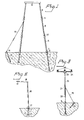
- Figure 1 illustrates a post or mast construction intended for supporting overhead high-tension cables;
- Figure 2 illustrates a lamp post construction; and
- Figure 3 illustrates a post construction for supporting power lines.
- The illustrated post construction includes a tubular post section 1 which is intended to be driven into the ground such as to provide a post foundation therein and to which there is fitted a
pole shoe 2. Oneend 3 of the foundation-forming post section 1 is spiked and the pole shoe is fitted to this spiked end by means of legs (not shown) which extend upwardly internally of said post section, or with the aid of a connecting socket which embraces saidspiked end 3. The opposite end of the foundation forming post section 1 is provided with a conical connectingsocket 4 into which there is inserted an auxiliary or bridgingpost section 5, the two ends of which have a spiked configuration which corresponds to the conicity of thesocket 4. Fitted to the spiked end of theauxiliary post section 5 distal from the foundation-forming post section 1 is the connectingsocket 7 of afirst post section 6. - The
socket 7 on thefirst post section 6 has an internal conicity which coincides fully with the conicity of the upper spiked end of theauxiliary section 5. This conicity has a tapering ratio of at least 1:14 and at most 1:20, i.e. the diameter decreases one length unit in an axial direction over a maximum of 20 length units. - As illustrated in Figure 1, a second, and optionally
several post sections 8, 9 can be fitted consecutively above thefirst post section 6, the number of sections fitted being dependent on the desired height of the post assembly. When the load to be supported permits, thehigher post sections 8, 9 may have a diameter which decreases in relation to theunderlying post section 6. This is achieved in accordance with the invention with the aid ofadapters respective post sections socket 7 of thefirst post section 6, theadapter 10 being fitted to the spike end of said first post section. In addition to length, a further difference between a diameter-reducing adapter and a post section is that the spiked end of the adapter has a diameter which corresponds to the inner diameter of the connecting socket on the post section to be placed above the diameter-decreasing adapter. - When erecting posts intended for supporting high-tension cables, it may be necessary to drive two or more foundation-forming post sections 1, 1ʹ into the ground. These foundation-forming post sections are configured in a similar manner to the overhead post sections, i.e. each have mutually corresponding connecting
sockets 4 and spiked ends 3 with self-locking facilities. These foundation-forming sections can be driven straight into the ground to provide a stable foundation at a requisite depth so as to provide the necessary support, even in ground which would not otherwise be considered suitable for the erection of such posts or masts. The diameter-reducing adapters are placed approximately 10 metres apart, even though shorter post sections should be used. - Tressel-like post configurations are used for supporting high-tension cables of 130 kV. The supporting tressels comprise two posts which extend vertically or are inclined one towards the other and which are interconnected at the top of respective sections by means of a horizontal connecting
bridge 12, which may comprise either a single post section or a number of interfitted post sections. The post section or sections forming the connectingbridge 12 must have a larger diameter than the post sections forming the limbs of the tressel-like structure. The holes required in the connectingbridge 12 to enable the bridge to be fitted over the pointed ends of the uppermost post sections can be formed with the aid of a conical boring tool provided in the high-tension cable construction equipment and which has the same cutting angle as the spiked ends of respective post sections 9. The connectingbridge 12 can be anchored to the top post elements 9 with the aid of a vibrating device. Attachment devices for the insulators from which the high-tension cables are to be suspended are screwed firmly into the connectingbridge 12. - When it is necessary to support a post, for example due to its height, there may be used a guy arrangement of the kind referenced 13, 14 and 15 in Figure 1. The guy peg used to this end may comprise a foundation-forming post section 1, which may or may not be fitted with a driving
shoe 2, or may comprise a post element of desired diameter which is driven into the ground at an acute angle to the surface thereof. Concrete is then poured into thehollow guy peg 13 and aneye bolt 14 is secured in the concrete. - A
guy wire 15 connected to the post at a suitable height thereon is then connected to theeye bolt 14 and tensioned. Alternatively, the eye bolt may comprise guy wire which is wound around the post section beneath the connecting socket, therewith eliminating the need of filling the post section with concrete. - When the inventive post is to be used as a lamp post, the foundation-forming post section 1 is driven into the ground in the aforedescribed manner. Subsequent to fitting the
auxiliary post section 5 into the connectingsocket 4, the connectingsocket 17 of alamp post 16 is fitted over the upper spiked end of theauxiliary section 5. Thepost 16 preferably tapers continuously upwards and may consists of a single-piece structure to a height of 5 metres. Fitted to the upper spiked end of thepost 16 is a single arm or double-arm element 18 which carries alamp 19 at the extremities of respective arms. The electric wires required for connecting-up the lamp or lamps can be readily drawn through the hollow post as the post is being erected. - In the case of high lamp posts, there is applied the same technique as that applied when erecting, for instance, posts which are to support 20 kV power cables. The foundation-forming post section is driven into the ground in the manner aforedescribed whereafter a
post section 20 is fitted over theauxiliary post section 5. Thepost section 20 of this embodiment differs from the aforementioned post sections, in that thespiked end 21 of thepost section 20 decreases in diameter stepwise at the location where its cone begins to converge. Thepost section 20 has fitted thereto anoverlying post section 22 which is provided with a connecting socket whose outer diameter is equal to the outer diameter of thepost sec tion 20. Thepost section 22 tapers upwards from the connecting socket to a given point on said section, whereafter the diameter of the section remains constant. Connected to the spiked end of thepost section 22 is a T-piece 23, the vertical leg of which is configured as the connecting socket on one of the aforedescribed post sections. The horizontal part of the T-piece 23 has the form of a hollow sleeve of uniform diameter. Extending through the horizontal sleeve is a smooth iron tube which forms acrosspiece 24, which is secured to the T-piece 23 by means of a preferably conical locking pin which is driven into a hole drilled through the T-piece 23 and into thecrosspiece 24. Thecrosspiece 24 is intended to support lamp fittings or power-cable insulators 25, which ever are required. - In the majority of cases it is preferred to assemble the post sections on the ground. The post is assembled by placing the connecting
socket 7 of thefirst post section 6 against a firm abutment, whereafter the diameter-reducingadapter 10 is fitted to the spiked end of thepost section 6. The connecting socket of thesecond post section 8 is then fitted onto theadapter 10 and an annular vibrating device is placed around the connecting socket of thepost section 8 and the parts are hammered together. As an additional safety measure, a conical locking pin or like device can be driven into a hole drilled through each connecting socket and into the spiked end of a post section located in said socket. Assembly of the post is continued until the requisite number of post sections have been fitted together, whereafter the post is erected. - The assembled post can be raised with the aid of a relatively powerful tractor-carried digger, even though the ground around the post has been highly compacted when driving in the foundation-forming section 1, which in itself contributes towards firming the post. The use of a tractor-carried digger affords a practical solution both when erecting a single post and when erecting a complete power-cable installation. In view of their very long useful life, posts constructed in accordance with the invention afford an economically advantageous alternative, particularly with regard to their re-usability.
Claims (12)
Priority Applications (1)
| Application Number | Priority Date | Filing Date | Title |
|---|---|---|---|
| AT88850089T ATE69853T1 (en) | 1987-03-30 | 1988-03-16 | POST STRUCTURE. |
Applications Claiming Priority (2)
| Application Number | Priority Date | Filing Date | Title |
|---|---|---|---|
| SE8701331 | 1987-03-30 | ||
| SE8701331A SE460137B (en) | 1987-03-30 | 1987-03-30 | POST |
Publications (3)
| Publication Number | Publication Date |
|---|---|
| EP0285584A2 true EP0285584A2 (en) | 1988-10-05 |
| EP0285584A3 EP0285584A3 (en) | 1989-10-04 |
| EP0285584B1 EP0285584B1 (en) | 1991-11-27 |
Family
ID=20368049
Family Applications (1)
| Application Number | Title | Priority Date | Filing Date |
|---|---|---|---|
| EP88850089A Expired - Lifetime EP0285584B1 (en) | 1987-03-30 | 1988-03-16 | A post structure |
Country Status (9)
| Country | Link |
|---|---|
| US (1) | US4899511A (en) |
| EP (1) | EP0285584B1 (en) |
| JP (1) | JPS63284375A (en) |
| AT (1) | ATE69853T1 (en) |
| DE (1) | DE3866398D1 (en) |
| DK (1) | DK173188A (en) |
| FI (1) | FI86755C (en) |
| NO (1) | NO164189C (en) |
| SE (1) | SE460137B (en) |
Cited By (1)
| Publication number | Priority date | Publication date | Assignee | Title |
|---|---|---|---|---|
| US5081804A (en) * | 1989-09-08 | 1992-01-21 | Gustavsberg Vvs Aktiebolag | Power line pylon and lamp post |
Families Citing this family (4)
| Publication number | Priority date | Publication date | Assignee | Title |
|---|---|---|---|---|
| CA2507332C (en) * | 2005-04-29 | 2012-01-10 | Robert Johnson | Metal support column shipping assembly |
| CN103741982A (en) * | 2014-01-16 | 2014-04-23 | 于佩 | Nodular cast iron insertion pole |
| CN105715092A (en) * | 2016-02-16 | 2016-06-29 | 国网山东省电力公司淄博供电公司 | Application of nodular cast iron pipes to combined tower for power transmission |
| USD971780S1 (en) * | 2022-07-11 | 2022-12-06 | Jiaxing Nanhu District Canshan Display Equipment Factory | Flagpole |
Family Cites Families (20)
| Publication number | Priority date | Publication date | Assignee | Title |
|---|---|---|---|---|
| US232360A (en) * | 1880-09-21 | William ii | ||
| US862152A (en) * | 1906-06-15 | 1907-08-06 | Solomon German | Fire shield and extinguisher. |
| US1342847A (en) * | 1919-02-05 | 1920-06-08 | George F Gray | Knockdown mast |
| US2016011A (en) * | 1933-08-18 | 1935-10-01 | Kent Arnold Frederick | Wireless aerial |
| US2162675A (en) * | 1937-10-08 | 1939-06-13 | John E Lingo & Son Inc | Mast for radio broadcasting |
| US2410246A (en) * | 1943-04-17 | 1946-10-29 | Masts Ltd | Mast, pole, and the like |
| CH244210A (en) * | 1944-09-25 | 1946-08-31 | Autophon Ag | Transportable mast. |
| US3325950A (en) * | 1964-09-03 | 1967-06-20 | Pfaff & Kendall | Lighting standard |
| US3270480A (en) * | 1965-04-07 | 1966-09-06 | Beecker William | Tapered sectional support pole |
| JPS4860435A (en) * | 1971-11-30 | 1973-08-24 | ||
| AT322814B (en) * | 1973-08-06 | 1975-06-10 | Birtner Ludwig | PIPE CONNECTION FOR SUPPORTING STRUCTURES |
| AT364146B (en) * | 1974-11-20 | 1981-09-25 | Steinbichler Josef | PIPE POLE |
| DE2708664A1 (en) * | 1976-03-01 | 1977-09-15 | Michel Leclerc | Overhead cable support pylon - has assembled repairable free part and ground sunken plinth component |
| US4076281A (en) * | 1976-04-13 | 1978-02-28 | Davis Samuel H | Bell fitting and support assembly for pipe |
| US4314434A (en) * | 1977-07-07 | 1982-02-09 | Meisberger Raymond F | Utility line support structure |
| CH643026A5 (en) * | 1979-10-11 | 1984-05-15 | Hans Kuersteiner | Hollow mast for lighting installations and lines |
| SE458863B (en) * | 1979-12-19 | 1989-05-16 | Gustavsberg Ab | PAALKONSTRUKTION |
| EP0067903A3 (en) * | 1981-06-24 | 1983-07-27 | Vulkan Werk für Industrie- und Aussenbeleuchtung GmbH | Tubular mast constituted of stacked elements |
| DE3145882C2 (en) * | 1981-11-19 | 1985-05-02 | Eskilstuna Invest AB, Eskilstuna | Method of making a foundation for a mast or the like. |
| US4543218A (en) * | 1984-07-17 | 1985-09-24 | Ceramic Cooling Tower Company | Cooling tower with concrete support structure, fiberglass panels, and a fan supported by the liquid distribution system |
-
1987
- 1987-03-30 SE SE8701331A patent/SE460137B/en not_active IP Right Cessation
-
1988
- 1988-03-16 DE DE8888850089T patent/DE3866398D1/en not_active Expired - Fee Related
- 1988-03-16 EP EP88850089A patent/EP0285584B1/en not_active Expired - Lifetime
- 1988-03-16 AT AT88850089T patent/ATE69853T1/en not_active IP Right Cessation
- 1988-03-24 FI FI881401A patent/FI86755C/en not_active IP Right Cessation
- 1988-03-25 NO NO881356A patent/NO164189C/en unknown
- 1988-03-29 JP JP63073491A patent/JPS63284375A/en active Pending
- 1988-03-29 US US07/174,766 patent/US4899511A/en not_active Expired - Fee Related
- 1988-03-29 DK DK173188A patent/DK173188A/en active IP Right Grant
Cited By (1)
| Publication number | Priority date | Publication date | Assignee | Title |
|---|---|---|---|---|
| US5081804A (en) * | 1989-09-08 | 1992-01-21 | Gustavsberg Vvs Aktiebolag | Power line pylon and lamp post |
Also Published As
| Publication number | Publication date |
|---|---|
| DK173188A (en) | 1988-10-01 |
| FI881401A0 (en) | 1988-03-24 |
| DK173188D0 (en) | 1988-03-29 |
| DE3866398D1 (en) | 1992-01-09 |
| SE8701331L (en) | 1988-10-01 |
| FI86755B (en) | 1992-06-30 |
| NO881356D0 (en) | 1988-03-25 |
| NO164189B (en) | 1990-05-28 |
| JPS63284375A (en) | 1988-11-21 |
| SE8701331D0 (en) | 1987-03-30 |
| ATE69853T1 (en) | 1991-12-15 |
| NO164189C (en) | 1990-09-05 |
| FI881401L (en) | 1988-10-01 |
| FI86755C (en) | 1992-10-12 |
| SE460137B (en) | 1989-09-11 |
| NO881356L (en) | 1988-10-03 |
| US4899511A (en) | 1990-02-13 |
| EP0285584A3 (en) | 1989-10-04 |
| EP0285584B1 (en) | 1991-11-27 |
Similar Documents
| Publication | Publication Date | Title |
|---|---|---|
| US20020067959A1 (en) | Retaining wall support posts | |
| US6557312B2 (en) | Prefabricated-building tower foundation | |
| US20210381188A1 (en) | Ground Anchor | |
| US5081804A (en) | Power line pylon and lamp post | |
| WO2000046452A1 (en) | Support structure for elevating and supporting monopoles and associated equipment | |
| WO1993012312A1 (en) | Ground anchors | |
| EP0285584B1 (en) | A post structure | |
| US5022134A (en) | Method of repairing/replacing a pole and associated pole replacement system | |
| US4052827A (en) | Ground anchor and foundation support | |
| EP2388878A2 (en) | Transmission line tower | |
| KR100648419B1 (en) | Electric pole support structure | |
| AU2020100517A4 (en) | Pole base replacement method and support assembly | |
| KR20100033750A (en) | A fixing structure of electric and construction method thereof | |
| CN210714039U (en) | Electric pole fixing device | |
| GB2314860A (en) | Post support | |
| KR101764407B1 (en) | Stone net structure and construction method using thereof | |
| KR100343970B1 (en) | Underground buried method of barbed pedestal for ground fixing | |
| CN215978723U (en) | Telegraph pole mounting base | |
| JPH076302B2 (en) | Self-supporting utility pole and its construction method | |
| CN217106405U (en) | High-stability transmission line iron tower | |
| CN211448028U (en) | Intelligence pole base | |
| CN121566324A (en) | Quick-release door type insulating crossing frame | |
| CN213869242U (en) | Outdoor fence for soft land | |
| CN217557894U (en) | Prestressed electric pole with lightning conductor | |
| AU751023B2 (en) | Retaining wall support posts |
Legal Events
| Date | Code | Title | Description |
|---|---|---|---|
| PUAI | Public reference made under article 153(3) epc to a published international application that has entered the european phase |
Free format text: ORIGINAL CODE: 0009012 |
|
| AK | Designated contracting states |
Kind code of ref document: A2 Designated state(s): AT BE CH DE ES FR GB GR IT LI LU NL |
|
| PUAL | Search report despatched |
Free format text: ORIGINAL CODE: 0009013 |
|
| AK | Designated contracting states |
Kind code of ref document: A3 Designated state(s): AT BE CH DE ES FR GB GR IT LI LU NL |
|
| 17P | Request for examination filed |
Effective date: 19900323 |
|
| 17Q | First examination report despatched |
Effective date: 19901002 |
|
| GRAA | (expected) grant |
Free format text: ORIGINAL CODE: 0009210 |
|
| RAP1 | Party data changed (applicant data changed or rights of an application transferred) |
Owner name: AB GUSTAVSBERG |
|
| AK | Designated contracting states |
Kind code of ref document: B1 Designated state(s): AT BE CH DE ES FR GB GR IT LI LU NL |
|
| PG25 | Lapsed in a contracting state [announced via postgrant information from national office to epo] |
Ref country code: BE Effective date: 19911127 |
|
| REF | Corresponds to: |
Ref document number: 69853 Country of ref document: AT Date of ref document: 19911215 Kind code of ref document: T |
|
| REF | Corresponds to: |
Ref document number: 3866398 Country of ref document: DE Date of ref document: 19920109 |
|
| ITF | It: translation for a ep patent filed | ||
| PG25 | Lapsed in a contracting state [announced via postgrant information from national office to epo] |
Ref country code: GR Free format text: LAPSE BECAUSE OF FAILURE TO SUBMIT A TRANSLATION OF THE DESCRIPTION OR TO PAY THE FEE WITHIN THE PRESCRIBED TIME-LIMIT Effective date: 19920228 Ref country code: ES Free format text: LAPSE BECAUSE OF FAILURE TO SUBMIT A TRANSLATION OF THE DESCRIPTION OR TO PAY THE FEE WITHIN THE PRESCRIBED TIME-LIMIT Effective date: 19920228 |
|
| PGFP | Annual fee paid to national office [announced via postgrant information from national office to epo] |
Ref country code: CH Payment date: 19920311 Year of fee payment: 5 |
|
| PGFP | Annual fee paid to national office [announced via postgrant information from national office to epo] |
Ref country code: GB Payment date: 19920313 Year of fee payment: 5 |
|
| PGFP | Annual fee paid to national office [announced via postgrant information from national office to epo] |
Ref country code: AT Payment date: 19920320 Year of fee payment: 5 |
|
| PGFP | Annual fee paid to national office [announced via postgrant information from national office to epo] |
Ref country code: NL Payment date: 19920331 Year of fee payment: 5 Ref country code: FR Payment date: 19920331 Year of fee payment: 5 |
|
| ET | Fr: translation filed | ||
| PGFP | Annual fee paid to national office [announced via postgrant information from national office to epo] |
Ref country code: LU Payment date: 19920413 Year of fee payment: 5 |
|
| PGFP | Annual fee paid to national office [announced via postgrant information from national office to epo] |
Ref country code: DE Payment date: 19920421 Year of fee payment: 5 |
|
| PLBI | Opposition filed |
Free format text: ORIGINAL CODE: 0009260 |
|
| 26 | Opposition filed |
Opponent name: TIROLER ROEHREN UND METALLWERKE AG Effective date: 19920826 |
|
| EPTA | Lu: last paid annual fee | ||
| NLR1 | Nl: opposition has been filed with the epo |
Opponent name: TIROLER ROEHREN UND METALLWERKE AG |
|
| PG25 | Lapsed in a contracting state [announced via postgrant information from national office to epo] |
Ref country code: LU Free format text: LAPSE BECAUSE OF NON-PAYMENT OF DUE FEES Effective date: 19930316 Ref country code: GB Effective date: 19930316 Ref country code: AT Effective date: 19930316 |
|
| PG25 | Lapsed in a contracting state [announced via postgrant information from national office to epo] |
Ref country code: LI Free format text: LAPSE BECAUSE OF NON-PAYMENT OF DUE FEES Effective date: 19930331 Ref country code: CH Free format text: LAPSE BECAUSE OF NON-PAYMENT OF DUE FEES Effective date: 19930331 |
|
| PG25 | Lapsed in a contracting state [announced via postgrant information from national office to epo] |
Ref country code: NL Effective date: 19931001 |
|
| GBPC | Gb: european patent ceased through non-payment of renewal fee |
Effective date: 19930316 |
|
| NLV4 | Nl: lapsed or anulled due to non-payment of the annual fee | ||
| PG25 | Lapsed in a contracting state [announced via postgrant information from national office to epo] |
Ref country code: FR Effective date: 19931130 |
|
| REG | Reference to a national code |
Ref country code: CH Ref legal event code: PL |
|
| PG25 | Lapsed in a contracting state [announced via postgrant information from national office to epo] |
Ref country code: DE Effective date: 19931201 |
|
| REG | Reference to a national code |
Ref country code: FR Ref legal event code: ST |
|
| RDAG | Patent revoked |
Free format text: ORIGINAL CODE: 0009271 |
|
| STAA | Information on the status of an ep patent application or granted ep patent |
Free format text: STATUS: PATENT REVOKED |
|
| 27W | Patent revoked |
Effective date: 19940606 |