EP0285363B1 - Rotary valves - Google Patents
Rotary valves Download PDFInfo
- Publication number
- EP0285363B1 EP0285363B1 EP88302766A EP88302766A EP0285363B1 EP 0285363 B1 EP0285363 B1 EP 0285363B1 EP 88302766 A EP88302766 A EP 88302766A EP 88302766 A EP88302766 A EP 88302766A EP 0285363 B1 EP0285363 B1 EP 0285363B1
- Authority
- EP
- European Patent Office
- Prior art keywords
- rotor
- valve rotor
- shaft
- port
- valve
- Prior art date
- Legal status (The legal status is an assumption and is not a legal conclusion. Google has not performed a legal analysis and makes no representation as to the accuracy of the status listed.)
- Expired - Lifetime
Links
Images
Classifications
-
- F—MECHANICAL ENGINEERING; LIGHTING; HEATING; WEAPONS; BLASTING
- F01—MACHINES OR ENGINES IN GENERAL; ENGINE PLANTS IN GENERAL; STEAM ENGINES
- F01L—CYCLICALLY OPERATING VALVES FOR MACHINES OR ENGINES
- F01L7/00—Rotary or oscillatory slide valve-gear or valve arrangements
- F01L7/08—Rotary or oscillatory slide valve-gear or valve arrangements with conically or frusto-conically shaped valves
-
- F—MECHANICAL ENGINEERING; LIGHTING; HEATING; WEAPONS; BLASTING
- F01—MACHINES OR ENGINES IN GENERAL; ENGINE PLANTS IN GENERAL; STEAM ENGINES
- F01L—CYCLICALLY OPERATING VALVES FOR MACHINES OR ENGINES
- F01L7/00—Rotary or oscillatory slide valve-gear or valve arrangements
- F01L7/06—Rotary or oscillatory slide valve-gear or valve arrangements with disc type valves
Definitions
- the present invention relates to a cylinder head with rotary valve suitable for an internal combustion engine, such as known from GB-A-559830 or GB-A-691275.
- a cylinder head comprises a rotary valve including a valve rotor having an annular discontinuity, the valve being mounted on a shaft for rotation relative to a port so that as it rotates, the discontinuity will open and close the port, drive means being provided to rotate the valve rotor, said drive means including means to reduce the speed of the valve rotor when the port is closed, the port being surrounded by a seating area and means being provided to move the valve rotor so that it engages the seating area and closes the port, when the speed of the valve rotor is reduced and move the valve rotor away from the seating area when the speed of the valve rotor is increased, characterised in that the valve rotor is mounted on the shaft by inter-engaging screw threaded formations, the screw threads being arranged such that rotation of the shaft, when driven, will unscrew the screw threads, means being provided to limit rotation of the valve rotor relative to the shaft.
- the speed of the valve rotor is reduced until it is stationary or near stationary when the port is closed, so that wear between the seating area and the valve rotor will be minimised.
- This may be achieved as disclosed in; British Patent Application No. 8806519 (Publication No. 2203796), in which the drive is transmitted by means of a gear train, the drive gear having teeth over only a portion of its periphery, so that it will only mesh with and drive the driven gear which is connected to the valve rotor over a portion of each revolution of the drive gear, interlock means being provided to keep the driven gear and valve rotor stationary when out of mesh with the drive gear; or European Patent Application No. 88306849.6 (Publication No. 0306141) in which a linkage mechanism is used to provide a varying speed drive which is reduced to almost stationary while the port is closed.
- the change in momentum of the valve rotor as it slows down and speeds up is used to move the valve rotor into engagement with the seating area or away from the seating area respectively.
- a rotary valve mechanism for an internal combustion engine comprises a conical valve rotor 10 which is mounted for rotation in a conical cylinder head 11, on a shaft 12.
- the shaft 12 is mounted through a ball bearing 13 by which it is located axially while the valve rotor 10 is rotatably mounted in a recess 19 in the cylinder head 11, on roller bearing 14.
- the conical rotor 10 overlies an exhaust port 15 and an inlet port 16 in the cylinder head 11.
- a segment 17 is removed from the rotor 10 so that as it rotates it will open and close the ports 15 and 16.
- the exhaust and inlet ports 15 and 16 are positioned so that there is a space 18 therebetween which is greater than the segment 17 removed from the disc 10.
- An ignition device 19 is located through the cylinder head 11 in the portion thereof defined by space 18.
- a driven gear 20 is secured to shaft 12 on the outside of the cylinder head 11.
- the gear 20 meshes with the gear 21 which is mounted on a drive shaft 22 by which it is driven by the engine.
- the gear 21 is provided with teeth 24 around only part of its periphery, said teeth 24 meshing with teeth 25 on gear 20.
- the number of teeth 24 on gear 21 is equal to the number of teeth 25 on gear 20, so that for one revolution of gear 21 the gear 20 and rotor 10 will also rotate by one revolution.
- Drive is however interrupted when teeth 24 on gear 21 move out of mesh with teeth 25 on gear 20, over the portion 26 of the periphery of gear 21 which is without teeth.
- a flange formation 27 on gear 20 overlies the periphery of gear 21.
- An arcuate track 28 is provided on the flange formation 27 and a pin 29 mounted on gear 21 engages in this track 28 to prevent rotation of gear 20 and rotor 10, when the teeth 24 and 25 of gears 21 and 20 respectively, are out of mesh.
- the track 28 may be provided with lead in and exit portions which will, respectively, decelerate and accelerate the gear 20 and rotor 10, as described in British Patent Application No. 8806519.
- the shaft 12 is connected to the rotor 10 by means of a multi-start helical thread 30 which engages in a correspondingly threaded recessed portion 31 of the rotor 10.
- the thread 30 is such that rotation of the shaft 12 when driven by the gear train 20, 21 will unscrew the thread.
- Rotation of the rotor 10 relative to the shaft 12 is restricted to a few degrees, by means of a key 32 which is mounted on the shaft 12 and engages in a pair of diametric slots 33 in the upper face of the recessed portion 31 of rotor 10, as illustrated in detail in Figure 3.
- a light torsion of spring 35 acts between the shaft 12 and rotor 10 to bias the rotor 10 in the direction of rotation of shaft 12, when driven.
- the above embodiment thus provides a rotary valve mechanism in which the valve rotor is driven intermittently, the rotor being seated against the cylinder head to seal the ports when stationary and being lifted away from the cylinder head when rotating.
- the valve mechanism consequently offers all the advantages of a rotary valve mechanism while providing positive seating which will produce sealing of the ports equivalent to that of poppet valves. Engagement of the valve rotor against the cylinder head will also assist in cooling of the rotor and help avoid pre-ignition problems.
- valve rotors described above are in the form of a cone or disc with a single aperture, cones or discs with one or more apertures may be used.
Landscapes
- Engineering & Computer Science (AREA)
- Mechanical Engineering (AREA)
- General Engineering & Computer Science (AREA)
- Valve-Gear Or Valve Arrangements (AREA)
- Gear-Shifting Mechanisms (AREA)
- Lubrication Of Internal Combustion Engines (AREA)
- Electrically Driven Valve-Operating Means (AREA)
- Valve Device For Special Equipments (AREA)
Abstract
Description
- The present invention relates to a cylinder head with rotary valve suitable for an internal combustion engine, such as known from GB-A-559830 or GB-A-691275.
- It has been proposed hitherto to use rotary valves for internal combustion engines, but in order to seal with the rotating valve member on the high pressure (ie compression and combustion) strokes of the engine, complex gas seals have been required. Furthermore, such systems result in high frictional loads with consequent reduction inefficiency and high wear rates. In order to reduce the problems of high frictional loads, it has been proposed to reduce the speed of rotation of the valves on the high pressure strokes of the engine, using a differential drive gear arrangement.
- According to one aspect of the present invention a cylinder head comprises a rotary valve including a valve rotor having an annular discontinuity, the valve being mounted on a shaft for rotation relative to a port so that as it rotates, the discontinuity will open and close the port, drive means being provided to rotate the valve rotor, said drive means including means to reduce the speed of the valve rotor when the port is closed, the port being surrounded by a seating area and means being provided to move the valve rotor so that it engages the seating area and closes the port, when the speed of the valve rotor is reduced and move the valve rotor away from the seating area when the speed of the valve rotor is increased, characterised in that the valve rotor is mounted on the shaft by inter-engaging screw threaded formations, the screw threads being arranged such that rotation of the shaft, when driven, will unscrew the screw threads, means being provided to limit rotation of the valve rotor relative to the shaft.
- Preferably the speed of the valve rotor is reduced until it is stationary or near stationary when the port is closed, so that wear between the seating area and the valve rotor will be minimised. This may be achieved as disclosed in; British Patent Application No. 8806519 (Publication No. 2203796), in which the drive is transmitted by means of a gear train, the drive gear having teeth over only a portion of its periphery, so that it will only mesh with and drive the driven gear which is connected to the valve rotor over a portion of each revolution of the drive gear, interlock means being provided to keep the driven gear and valve rotor stationary when out of mesh with the drive gear; or European Patent Application No. 88306849.6 (Publication No. 0306141) in which a linkage mechanism is used to provide a varying speed drive which is reduced to almost stationary while the port is closed.
- According to the invention, the change in momentum of the valve rotor as it slows down and speeds up is used to move the valve rotor into engagement with the seating area or away from the seating area respectively.
- The invention is now described, by way of example only, with reference to the accompanying drawings, in which:-
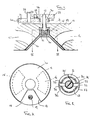
- Figure 1 illustrates in sectional side elevation a rotary valve according to the present invention;
- Figure 2 illustrates in plan from below, the valve rotor of the rotary valve illustrated in Figure 1; and
- Figure 3 is a section on enlarged scale along the line III-III of Figure 1.
- As illustrates in Figures 1 to 3, a rotary valve mechanism for an internal combustion engine comprises a conical valve rotor 10 which is mounted for rotation in a conical cylinder head 11, on a
shaft 12. Theshaft 12 is mounted through a ball bearing 13 by which it is located axially while the valve rotor 10 is rotatably mounted in arecess 19 in the cylinder head 11, on roller bearing 14. - The conical rotor 10 overlies an
exhaust port 15 and an inlet port 16 in the cylinder head 11. Asegment 17 is removed from the rotor 10 so that as it rotates it will open and close theports 15 and 16. The exhaust andinlet ports 15 and 16 are positioned so that there is aspace 18 therebetween which is greater than thesegment 17 removed from the disc 10. Anignition device 19 is located through the cylinder head 11 in the portion thereof defined byspace 18. - A driven gear 20 is secured to
shaft 12 on the outside of the cylinder head 11. The gear 20 meshes with thegear 21 which is mounted on adrive shaft 22 by which it is driven by the engine. Thegear 21 is provided with teeth 24 around only part of its periphery, said teeth 24 meshing withteeth 25 on gear 20. The number of teeth 24 ongear 21 is equal to the number ofteeth 25 on gear 20, so that for one revolution ofgear 21 the gear 20 and rotor 10 will also rotate by one revolution. Drive is however interrupted when teeth 24 ongear 21 move out of mesh withteeth 25 on gear 20, over theportion 26 of the periphery ofgear 21 which is without teeth. - A
flange formation 27 on gear 20 overlies the periphery ofgear 21. Anarcuate track 28 is provided on theflange formation 27 and a pin 29 mounted ongear 21 engages in thistrack 28 to prevent rotation of gear 20 and rotor 10, when theteeth 24 and 25 ofgears 21 and 20 respectively, are out of mesh. Thetrack 28 may be provided with lead in and exit portions which will, respectively, decelerate and accelerate the gear 20 and rotor 10, as described in British Patent Application No. 8806519. - The
shaft 12 is connected to the rotor 10 by means of a multi-starthelical thread 30 which engages in a correspondingly threadedrecessed portion 31 of the rotor 10. Thethread 30 is such that rotation of theshaft 12 when driven by thegear train 20, 21 will unscrew the thread. Rotation of the rotor 10 relative to theshaft 12 is restricted to a few degrees, by means of akey 32 which is mounted on theshaft 12 and engages in a pair ofdiametric slots 33 in the upper face of the recessedportion 31 of rotor 10, as illustrated in detail in Figure 3. A light torsion ofspring 35 acts between theshaft 12 and rotor 10 to bias the rotor 10 in the direction of rotation ofshaft 12, when driven. - When the
teeth 25 of gear 20 are out of mesh with the teeth 24 ofgear 21 and the rotor 10 is at rest with thesegment 17 overlyingportion 18 of the cylinder head 11, thetorsion spring 35 will ensure that the rotor 10 is screwed up on thethread 30 and will engage the cylinder head 11, to seal theports 15 and 16. Upon acceleration of theshaft 12 from rest, as the teeth 24 come back into mesh with theteeth 25, rotation of theshaft 12 will first unscrew thethread 30 from therecessed portion 31 of rotor 10, thus causing the rotor 10 to move away from the cylinder head 11,shaft 12 being fixed axially by ball bearing 13. Theshaft 12 will rotate relative to the rotor 10 against the bias of thespring 35. If the drive torque exceeds the spring load, then key 32 engages leadingface 37 of theslots 33, thus restricting any change in phase between theshaft 12 and rotor 10. At a constant velocity, thetorsion spring 35 will tend to seat the rotor 10 against the cylinder head 11, but drag therebetween will tend to unscrew the rotor 10 onthread 30 thus minimising any frictional engagement and wear between the rotor 10 and cylinder head 11. As the teeth 24 move out of mesh withteeth 25 and theshaft 12 and rotor 10 come to rest, the momentum of the rotor 10 will tend to screw the rotor 10 up onto the thread 20 so that the rotor 10 is moved into tight engagement with the cylinder head 11, where it is held bytorsion spring 35. - The above embodiment thus provides a rotary valve mechanism in which the valve rotor is driven intermittently, the rotor being seated against the cylinder head to seal the ports when stationary and being lifted away from the cylinder head when rotating. The valve mechanism consequently offers all the advantages of a rotary valve mechanism while providing positive seating which will produce sealing of the ports equivalent to that of poppet valves. Engagement of the valve rotor against the cylinder head will also assist in cooling of the rotor and help avoid pre-ignition problems.
- For example, while in the above embodiment only one dwell period is provided per revolution, more than one dwell period may be provided, the drive gear designed to provide multiple dwell points on each revolution. Although the valve rotors described above are in the form of a cone or disc with a single aperture, cones or discs with one or more apertures may be used.
Claims (5)
- A cylinder head comprising a rotary valve including a valve rotor (10) having an annular discontinuity (17), the valve rotor (10) being mounted on a shaft (12) for rotation relative to a port (15;16) so that as it rotates, the discontinuity (17) will open and close the port (15;16), drive means being provided to rotate the valve rotor (10), said drive means (20,21) including means (24,25) to reduce the speed of the valve rotor (10) when the port (15;16) is closed, the port (15;16) being surrounded by a seating area and means (30,31) being provided to move the valve rotor (10) so that it engages the seating area and closes the port (15;16), when the speed of the valve rotor is reduced and move the valve rotor (10) away from the seating area when the speed of the valve rotor (10) is increased, characterised in that the valve rotor (10) is mounted on the shaft (12) by inter-engaging screw threaded formations (30,31), the screw threads being arranged such that rotation of the shaft (12), when driven, will unscrew the screw threads, means (32,33) being provided to limit rotation of the valve rotor (10) relative to the shaft (12).
- A cylinder head according to Claim 1 characterised in that the screw threaded formations (30,31) are in the form of multi-start helices.
- A cylinder head according to Claim 1 or 2 characterised in that a key (32) is secured to the shaft (12) and engages in a slot (33) in the valve rotor (10), the slot (33) being extended in the plane of rotation, to provide for limited rotation between the valve rotor (10) and shaft (12).
- A cylinder head according to any one of Claims 1 to 3 characterised in that the valve rotor (10) is biased with respect to the shaft (12) in the direction of rotation of the shaft (12) when driven.
- A cylinder head according to any one of Claims 1 to 4 characterised in that bearing means (13) is provided to axially restrain the shaft (12), while the valve rotor (10) is mounted so that it is free to move axially.
Priority Applications (1)
| Application Number | Priority Date | Filing Date | Title |
|---|---|---|---|
| AT88302766T ATE70893T1 (en) | 1987-04-03 | 1988-03-29 | ROTARY VALVES. |
Applications Claiming Priority (2)
| Application Number | Priority Date | Filing Date | Title |
|---|---|---|---|
| GB878708037A GB8708037D0 (en) | 1987-04-03 | 1987-04-03 | Rotary valves |
| GB8708037 | 1987-04-03 |
Publications (3)
| Publication Number | Publication Date |
|---|---|
| EP0285363A2 EP0285363A2 (en) | 1988-10-05 |
| EP0285363A3 EP0285363A3 (en) | 1989-02-08 |
| EP0285363B1 true EP0285363B1 (en) | 1991-12-27 |
Family
ID=10615204
Family Applications (1)
| Application Number | Title | Priority Date | Filing Date |
|---|---|---|---|
| EP88302766A Expired - Lifetime EP0285363B1 (en) | 1987-04-03 | 1988-03-29 | Rotary valves |
Country Status (5)
| Country | Link |
|---|---|
| US (1) | US4838220A (en) |
| EP (1) | EP0285363B1 (en) |
| AT (1) | ATE70893T1 (en) |
| DE (1) | DE3867106D1 (en) |
| GB (2) | GB8708037D0 (en) |
Cited By (4)
| Publication number | Priority date | Publication date | Assignee | Title |
|---|---|---|---|---|
| DE102007018433A1 (en) | 2007-04-19 | 2008-10-30 | ThyssenKrupp Metalúrgica Campo Limpo Ltda. | Inlet and exhaust valve assembly for an internal combustion engine |
| DE102012100947A1 (en) | 2012-02-06 | 2013-08-08 | Voestalpine Bwg Gmbh & Co. Kg | Track portion for rail, has resilient element having spring characteristic, where resilient element extends itself in recess of foot portion, and resilient element has thickness and rigidity such that gap with core is unchanged |
| DE102012100957A1 (en) | 2012-02-06 | 2013-08-08 | Voestalpine Bwg Gmbh & Co. Kg | Track portion for rail vehicle, has elastic element partially extended in recesses of supporting part and/or foot portion of core and exhibiting thickness and elasticity such that distance is unchanged when core is unstressed |
| WO2013117325A1 (en) | 2012-02-06 | 2013-08-15 | Voestalpine Bwg Gmbh & Co. Kg | Track section for a rail and method for increasing the elastic bedding |
Families Citing this family (14)
| Publication number | Priority date | Publication date | Assignee | Title |
|---|---|---|---|---|
| FR2621956A1 (en) * | 1987-10-16 | 1989-04-21 | Pellerin Jacques | INTERNAL COMBUSTION ENGINE WITH ROTARY DISTRIBUTION |
| ES2060473B1 (en) * | 1991-05-17 | 1996-11-16 | Dodas Ramon Verdaguer | PERFECTED INTERNAL COMBUSTION ENGINE. |
| US5257601A (en) * | 1993-02-01 | 1993-11-02 | Coffin David F | Adjustable rotary valve assembly for a combustion engine |
| US5967108A (en) * | 1996-09-11 | 1999-10-19 | Kutlucinar; Iskender | Rotary valve system |
| US5931134A (en) * | 1997-05-05 | 1999-08-03 | Devik International, Inc. | Internal combustion engine with improved combustion |
| IT1292223B1 (en) * | 1997-05-07 | 1999-01-29 | Giorgio Enrico Falck | INTERNAL COMBUSTION ENGINE EQUIPPED WITH ROTATING SLEEVE TIMING |
| FR2776704A1 (en) * | 1998-03-27 | 1999-10-01 | Daniel Drecq | ASSEMBLY COMPRISING A VALVE ASSOCIATED WITH AT LEAST ONE DUCT AND HEAT MOTOR EQUIPPED WITH THIS ASSEMBLY |
| KR100461451B1 (en) * | 2002-05-14 | 2004-12-14 | 현대자동차주식회사 | Rotation type valve device |
| US7658169B2 (en) | 2005-03-09 | 2010-02-09 | Zajac Optimum Output Motors, Inc. | Internal combustion engine and method with improved combustion chamber |
| WO2008018842A1 (en) * | 2006-08-09 | 2008-02-14 | Jozef Cekan | Four-stroke combustion engine with rotating segment in distributing mechanism |
| CH704346B1 (en) * | 2007-02-05 | 2012-07-13 | Imtmedical Ag | Control valve for ventilators. |
| IT1393762B1 (en) * | 2008-12-15 | 2012-05-08 | Burgio Di Aragona | DEVICE FOR THE INTERMITTENT ROTATION COMMAND OF A SUCTION AND EXHAUST VALVE FOR INTERNAL COMBUSTION ENGINES. |
| DE102011010137B4 (en) * | 2011-02-03 | 2014-02-13 | Willi Rehwald | Mechanisms for controlling the gas exchange in four-stroke internal combustion engines |
| US20220307391A1 (en) * | 2019-06-03 | 2022-09-29 | Steve Burkholder | Plate valve four stoke head |
Family Cites Families (17)
| Publication number | Priority date | Publication date | Assignee | Title |
|---|---|---|---|---|
| FR15749E (en) * | 1912-09-09 | Societe Des Etablissements Malicet Et Blin | Method for controlling in rotation a mobile fixed to slide along a fixed guide wall and devices producing it | |
| GB253213A (en) * | ||||
| FR15916E (en) * | 1911-03-08 | 1912-10-19 | Societe Des Etablissements Malicet Et Blin | Method for controlling in rotation a mobile fixed to slide along a fixed guide wall and devices producing it |
| GB158269A (en) * | 1920-01-21 | 1921-11-17 | Frederick Ridley Dennison | Improvements in or relating to rotary valves |
| US1799759A (en) * | 1927-03-14 | 1931-04-07 | Mcdowell George | Valve for internal-combustion engines |
| GB559830A (en) * | 1943-01-26 | 1944-03-07 | Edward Ambrose Mellors | Improvements relating to valve mechanisms for internal combustion engines |
| US2457206A (en) * | 1945-03-16 | 1948-12-28 | Bert G Carlson | Rotary valve for internalcombustion engines |
| GB691275A (en) * | 1949-12-05 | 1953-05-06 | Ercole Colombo | Improvements in or relating to rotary valve internal combustion piston engines |
| GB687298A (en) * | 1950-07-05 | 1953-02-11 | Kaye S Rotaprint Agency Ltd | Improvements in and relating to sheet feeding means for printing or duplicating machines |
| GB725088A (en) * | 1953-07-31 | 1955-03-02 | Gleason Works | Improvements relating to intermittent mechanical motions |
| GB899724A (en) * | 1958-11-11 | 1962-06-27 | Hisakichi Ichinose | Improvements in or relating to screen printing machines |
| GB900594A (en) * | 1959-01-20 | 1962-07-11 | Graphic Technology Ltd | Improved means for providing intermittent rotary motion |
| US3274901A (en) * | 1964-09-28 | 1966-09-27 | Oscar A Yost | Oscillating port valve |
| GB1162053A (en) * | 1966-08-31 | 1969-08-20 | Omega Brandt & Freres Sa Louis | Device for Displaying a Sequence of Numbers |
| IT1136826B (en) * | 1980-04-23 | 1986-09-03 | Sulzer Ag | ARRANGEMENT FOR THE WASHING AND CHARGING OF CYLINDERS OF A TWO STROKE ENDOTHERMAL ENGINE |
| US4418658A (en) * | 1980-07-07 | 1983-12-06 | Diross James | Engine valve |
| GB2127482B (en) * | 1982-09-21 | 1986-08-13 | Herbert Ball | Internal combustion engine with an oscillating conical valve |
-
1987
- 1987-04-03 GB GB878708037A patent/GB8708037D0/en active Pending
-
1988
- 1988-03-18 GB GB8806519A patent/GB2203796B/en not_active Expired - Lifetime
- 1988-03-29 AT AT88302766T patent/ATE70893T1/en active
- 1988-03-29 DE DE8888302766T patent/DE3867106D1/en not_active Expired - Fee Related
- 1988-03-29 EP EP88302766A patent/EP0285363B1/en not_active Expired - Lifetime
- 1988-04-01 US US07/176,633 patent/US4838220A/en not_active Expired - Fee Related
Cited By (4)
| Publication number | Priority date | Publication date | Assignee | Title |
|---|---|---|---|---|
| DE102007018433A1 (en) | 2007-04-19 | 2008-10-30 | ThyssenKrupp Metalúrgica Campo Limpo Ltda. | Inlet and exhaust valve assembly for an internal combustion engine |
| DE102012100947A1 (en) | 2012-02-06 | 2013-08-08 | Voestalpine Bwg Gmbh & Co. Kg | Track portion for rail, has resilient element having spring characteristic, where resilient element extends itself in recess of foot portion, and resilient element has thickness and rigidity such that gap with core is unchanged |
| DE102012100957A1 (en) | 2012-02-06 | 2013-08-08 | Voestalpine Bwg Gmbh & Co. Kg | Track portion for rail vehicle, has elastic element partially extended in recesses of supporting part and/or foot portion of core and exhibiting thickness and elasticity such that distance is unchanged when core is unstressed |
| WO2013117325A1 (en) | 2012-02-06 | 2013-08-15 | Voestalpine Bwg Gmbh & Co. Kg | Track section for a rail and method for increasing the elastic bedding |
Also Published As
| Publication number | Publication date |
|---|---|
| DE3867106D1 (en) | 1992-02-06 |
| ATE70893T1 (en) | 1992-01-15 |
| EP0285363A3 (en) | 1989-02-08 |
| GB2203796A (en) | 1988-10-26 |
| GB2203796B (en) | 1991-09-25 |
| EP0285363A2 (en) | 1988-10-05 |
| US4838220A (en) | 1989-06-13 |
| GB8806519D0 (en) | 1988-04-20 |
| GB8708037D0 (en) | 1987-05-07 |
Similar Documents
| Publication | Publication Date | Title |
|---|---|---|
| EP0285363B1 (en) | Rotary valves | |
| US6523512B2 (en) | Control unit for adjusting the angle of rotation of a camshaft | |
| US6328008B1 (en) | Valve timing control system for internal combustion engine | |
| EP0292185B1 (en) | Cam mechanisms | |
| US20200182331A1 (en) | Gear transmission device | |
| US4570439A (en) | Exhaust control system for 2-cycle engines | |
| EP0279826B1 (en) | Differential camshaft | |
| JPH0960509A (en) | Variable valve timing device | |
| JPH04105906U (en) | Internal combustion engine valve timing control device | |
| JP2828361B2 (en) | Valve timing adjustment device | |
| EP0140514A1 (en) | Internal combustion engine with disc inlet valve | |
| US4545338A (en) | Cam shaft timing control device | |
| CN114402122A (en) | Internal combustion engine with camshaft valve phase changing device | |
| JPH0325610B2 (en) | ||
| JPH0211809A (en) | Valve opening/closing timing controller | |
| JPH04148023A (en) | Intake air control device for vehicle engine | |
| JPS6196112A (en) | Device for altering valve timing in 4-cycle engine | |
| JPH0213716Y2 (en) | ||
| JPH0311363Y2 (en) | ||
| KR20020054774A (en) | A vane type variable valve timing apparatus | |
| JP2895708B2 (en) | Valve timing control device | |
| JPH0262452A (en) | Rotary drive mechanism and assembly thereof | |
| EP0668435B1 (en) | Timing system for internal combustion engines | |
| JPS6141977Y2 (en) | ||
| JPH042780B2 (en) |
Legal Events
| Date | Code | Title | Description |
|---|---|---|---|
| PUAI | Public reference made under article 153(3) epc to a published international application that has entered the european phase |
Free format text: ORIGINAL CODE: 0009012 |
|
| AK | Designated contracting states |
Kind code of ref document: A2 Designated state(s): AT BE CH DE ES FR GB GR IT LI LU NL SE |
|
| PUAL | Search report despatched |
Free format text: ORIGINAL CODE: 0009013 |
|
| AK | Designated contracting states |
Kind code of ref document: A3 Designated state(s): AT BE CH DE ES FR GB GR IT LI LU NL SE |
|
| 17P | Request for examination filed |
Effective date: 19890306 |
|
| 17Q | First examination report despatched |
Effective date: 19900419 |
|
| GRAA | (expected) grant |
Free format text: ORIGINAL CODE: 0009210 |
|
| AK | Designated contracting states |
Kind code of ref document: B1 Designated state(s): AT BE CH DE ES FR GB GR IT LI LU NL SE |
|
| PG25 | Lapsed in a contracting state [announced via postgrant information from national office to epo] |
Ref country code: NL Effective date: 19911227 Ref country code: LI Effective date: 19911227 Ref country code: GR Free format text: LAPSE BECAUSE OF FAILURE TO SUBMIT A TRANSLATION OF THE DESCRIPTION OR TO PAY THE FEE WITHIN THE PRESCRIBED TIME-LIMIT Effective date: 19911227 Ref country code: ES Free format text: THE PATENT HAS BEEN ANNULLED BY A DECISION OF A NATIONAL AUTHORITY Effective date: 19911227 Ref country code: CH Effective date: 19911227 Ref country code: BE Effective date: 19911227 Ref country code: AT Effective date: 19911227 |
|
| REF | Corresponds to: |
Ref document number: 70893 Country of ref document: AT Date of ref document: 19920115 Kind code of ref document: T |
|
| REF | Corresponds to: |
Ref document number: 3867106 Country of ref document: DE Date of ref document: 19920206 |
|
| PGFP | Annual fee paid to national office [announced via postgrant information from national office to epo] |
Ref country code: FR Payment date: 19920210 Year of fee payment: 5 |
|
| PGFP | Annual fee paid to national office [announced via postgrant information from national office to epo] |
Ref country code: SE Payment date: 19920217 Year of fee payment: 5 Ref country code: GB Payment date: 19920217 Year of fee payment: 5 |
|
| PGFP | Annual fee paid to national office [announced via postgrant information from national office to epo] |
Ref country code: DE Payment date: 19920219 Year of fee payment: 5 |
|
| ITF | It: translation for a ep patent filed |
Owner name: JACOBACCI & PERANI S.P.A. |
|
| ET | Fr: translation filed | ||
| PG25 | Lapsed in a contracting state [announced via postgrant information from national office to epo] |
Ref country code: LU Free format text: LAPSE BECAUSE OF NON-PAYMENT OF DUE FEES Effective date: 19920331 |
|
| REG | Reference to a national code |
Ref country code: CH Ref legal event code: PL |
|
| NLV1 | Nl: lapsed or annulled due to failure to fulfill the requirements of art. 29p and 29m of the patents act | ||
| PLBE | No opposition filed within time limit |
Free format text: ORIGINAL CODE: 0009261 |
|
| STAA | Information on the status of an ep patent application or granted ep patent |
Free format text: STATUS: NO OPPOSITION FILED WITHIN TIME LIMIT |
|
| 26N | No opposition filed | ||
| PG25 | Lapsed in a contracting state [announced via postgrant information from national office to epo] |
Ref country code: GB Effective date: 19930329 |
|
| PG25 | Lapsed in a contracting state [announced via postgrant information from national office to epo] |
Ref country code: SE Effective date: 19930330 |
|
| GBPC | Gb: european patent ceased through non-payment of renewal fee |
Effective date: 19930329 |
|
| PG25 | Lapsed in a contracting state [announced via postgrant information from national office to epo] |
Ref country code: FR Effective date: 19931130 |
|
| PG25 | Lapsed in a contracting state [announced via postgrant information from national office to epo] |
Ref country code: DE Effective date: 19931201 |
|
| REG | Reference to a national code |
Ref country code: FR Ref legal event code: ST |
|
| EUG | Se: european patent has lapsed |
Ref document number: 88302766.6 Effective date: 19931008 |
|
| PG25 | Lapsed in a contracting state [announced via postgrant information from national office to epo] |
Ref country code: IT Free format text: LAPSE BECAUSE OF NON-PAYMENT OF DUE FEES;WARNING: LAPSES OF ITALIAN PATENTS WITH EFFECTIVE DATE BEFORE 2007 MAY HAVE OCCURRED AT ANY TIME BEFORE 2007. THE CORRECT EFFECTIVE DATE MAY BE DIFFERENT FROM THE ONE RECORDED. Effective date: 20050329 |