EP0285027A2 - Arrangement for mounting a catalyst in a casing in the exhaust system of a liquid fuel engine - Google Patents
Arrangement for mounting a catalyst in a casing in the exhaust system of a liquid fuel engine Download PDFInfo
- Publication number
- EP0285027A2 EP0285027A2 EP88104839A EP88104839A EP0285027A2 EP 0285027 A2 EP0285027 A2 EP 0285027A2 EP 88104839 A EP88104839 A EP 88104839A EP 88104839 A EP88104839 A EP 88104839A EP 0285027 A2 EP0285027 A2 EP 0285027A2
- Authority
- EP
- European Patent Office
- Prior art keywords
- knitted fabric
- sealing strip
- holding element
- section
- arrangement according
- Prior art date
- Legal status (The legal status is an assumption and is not a legal conclusion. Google has not performed a legal analysis and makes no representation as to the accuracy of the status listed.)
- Granted
Links
Images
Classifications
-
- F—MECHANICAL ENGINEERING; LIGHTING; HEATING; WEAPONS; BLASTING
- F01—MACHINES OR ENGINES IN GENERAL; ENGINE PLANTS IN GENERAL; STEAM ENGINES
- F01N—GAS-FLOW SILENCERS OR EXHAUST APPARATUS FOR MACHINES OR ENGINES IN GENERAL; GAS-FLOW SILENCERS OR EXHAUST APPARATUS FOR INTERNAL COMBUSTION ENGINES
- F01N3/00—Exhaust or silencing apparatus having means for purifying, rendering innocuous, or otherwise treating exhaust
- F01N3/08—Exhaust or silencing apparatus having means for purifying, rendering innocuous, or otherwise treating exhaust for rendering innocuous
- F01N3/10—Exhaust or silencing apparatus having means for purifying, rendering innocuous, or otherwise treating exhaust for rendering innocuous by thermal or catalytic conversion of noxious components of exhaust
- F01N3/24—Exhaust or silencing apparatus having means for purifying, rendering innocuous, or otherwise treating exhaust for rendering innocuous by thermal or catalytic conversion of noxious components of exhaust characterised by constructional aspects of converting apparatus
- F01N3/28—Construction of catalytic reactors
- F01N3/2839—Arrangements for mounting catalyst support in housing, e.g. with means for compensating thermal expansion or vibration
- F01N3/2853—Arrangements for mounting catalyst support in housing, e.g. with means for compensating thermal expansion or vibration using mats or gaskets between catalyst body and housing
- F01N3/2867—Arrangements for mounting catalyst support in housing, e.g. with means for compensating thermal expansion or vibration using mats or gaskets between catalyst body and housing the mats or gaskets being placed at the front or end face of catalyst body
-
- F—MECHANICAL ENGINEERING; LIGHTING; HEATING; WEAPONS; BLASTING
- F01—MACHINES OR ENGINES IN GENERAL; ENGINE PLANTS IN GENERAL; STEAM ENGINES
- F01N—GAS-FLOW SILENCERS OR EXHAUST APPARATUS FOR MACHINES OR ENGINES IN GENERAL; GAS-FLOW SILENCERS OR EXHAUST APPARATUS FOR INTERNAL COMBUSTION ENGINES
- F01N2350/00—Arrangements for fitting catalyst support or particle filter element in the housing
- F01N2350/02—Fitting ceramic monoliths in a metallic housing
- F01N2350/04—Fitting ceramic monoliths in a metallic housing with means compensating thermal expansion
-
- F—MECHANICAL ENGINEERING; LIGHTING; HEATING; WEAPONS; BLASTING
- F01—MACHINES OR ENGINES IN GENERAL; ENGINE PLANTS IN GENERAL; STEAM ENGINES
- F01N—GAS-FLOW SILENCERS OR EXHAUST APPARATUS FOR MACHINES OR ENGINES IN GENERAL; GAS-FLOW SILENCERS OR EXHAUST APPARATUS FOR INTERNAL COMBUSTION ENGINES
- F01N2350/00—Arrangements for fitting catalyst support or particle filter element in the housing
- F01N2350/02—Fitting ceramic monoliths in a metallic housing
- F01N2350/06—Fitting ceramic monoliths in a metallic housing with means preventing gas flow by-pass or leakage
Definitions
- the invention relates to an arrangement for holding a catalytic converter in a housing in the exhaust system of an engine operated with liquid fuel and sealing it against exhaust gas flowing around it by means of an at least single-layer, corrugated metallic knitted fabric surrounding the catalytic converter as a holding element which holds the catalytic converter in its installed position in the housing and which has at least one section running in the longitudinal direction of the holding element for receiving a sealing strip.
- DE-PS 22 13 539 shows a monolith holder, in which the surface of the body is covered with a pore-closing layer of aluminum silicate and then the actual holder is carried out by means of a corrugated metallic knitted fabric.
- DE-PS 22 13 539 it is also known to prevent flow around the body to be held by arranging one or more radial sealing rings between the holding body and the housing or the sealing impressions.
- a second, related problem is the sealing against the exhaust gas flow around the body. This flow ratio must be kept as low as possible, since the gas flowing through the body is cleaned as it flows through the body, e.g. a catalyst, while the gas flow around it remains untreated and is fed back to the exhaust gas behind the catalyst body and thus the efficiency of the cleaning belittles.
- the invention is therefore an object of the invention to show a generic bracket that is simple to manufacture and assemble, since it is a mass article and in which the tightness against flowing exhaust gas with simple means in a manner secured against destruction of the sealing element.
- the solution to the problem arises in a generic arrangement in that in the portion serving to receive the sealing strip of the holding element, the metallic threads of the knitted fabric are not deformed into the corrugated knitted shape and at least one sealing strip is introduced in this section formed in this way.
- the essence of the invention is that in the section of the holding element in which the sealing strip is introduced, no compressed knitted fabric, but only - viewed in the longitudinal section of the arrangement - there are smooth and preferably parallel metallic threads that connect the adjacent knitted parts, whereby these threads are those from which the knitted fabric is formed.
- the section runs in the longitudinal direction of the holding element, the width of the holding element corresponding approximately to the length of the catalytic monolith around which the holding element is wound, in one or more layers.
- the sealing strip lies transversely to the flow direction of the exhaust gas around the monolith.
- the holding element can be a hose knitted from metallic threads, which is not formed as a knitted fabric on the section designed according to the invention, but has straight threads, and which is then pressed together to form a flat, two-layer element, the knitting-free sections then being straight Threads lie on top of one another and thus form the section for receiving the sealing element.
- the holding element can also be designed as a correspondingly long single-layer element, for example of a length that is equal to or greater than twice the circumference of the monolith. In this case, the monolith is surrounded by the holding element in such a way that a two-layer covering is produced.
- a further development of the invention is characterized in that at least one sealing strip is inserted above or below or between the non-deformed metallic threads of the knitted fabric is brought.
- the sealing strip is inserted into the section provided for accommodating the monolith before it is wrapped around, and it can be placed on or under the straight threads.
- the sealing strip can already be inserted into the section provided for this purpose when the hose is pressed together, so that it lies between the straight threads and, if necessary, a further sealing strip can be used before wrapping the monolith in the section the straight threads are placed on the sealing strip already inserted, so that a double sealing strip is inserted after the monolith has been coated.
- the thickness of the sealing strip is equal to or less than the height of the corrugation of the knitted fabric at the sections adjacent to the receptacle of the sealing strip.
- an exemplary embodiment of the holder according to the invention is shown in simplified and schematic form, using the example of the holder of a catalytically coated monolith in the exhaust pipe of a vehicle.
- a body 1 which is a catalytically coated monolith with a large number of very fine longitudinal channels, is intended to be arranged and held in a pipe 11, in the present case the exhaust pipe of a vehicle.
- the flow of exhaust gas around the body 1 should also be prevented as far as possible and the holder should be sufficient in all operating states.
- the holder should be effective at the different temperatures, that is to say in a range from approximately 800 ° to 900 ° C.
- the exhaust pipe 11 has an inlet funnel 3a in the direction of flow, to which the cylindrical housing adjoins, in which the body 1 is held.
- the housing 2 can be connected to the inlet funnel 3a with a larger diameter, so that a contact edge is formed.
- the outlet funnel 3b connects to the housing 2 with the following pipeline.
- the housing 2 is either welded to the two funnels 3a, 3b or connected via flanges.
- the cylindrical housing 2 has circumferential impressions 12 which either run parallel to one another or are stamped in a spiral. This indentation 12 causes the pressing of the holding element 4, which surrounds the body 1.
- the holding element 4 consists of a 2-ply tubular knitted fabric made of wire with a diameter of 0.23 mm and made of Inconel 601 or Nicrofer 6023 and having a knitted width of 95 mm and 60 stitches, which is compressed into a flat element.
- the holding element 4 has an arrow-shaped indentation 5 on both sides. This creates a corrugation with a pitch of 10.5 mm at a height of the knitted fabric of 6.5 mm (corrugation h), the arrow path on both sides is 72 ° to the edge.
- the holding element 4 is provided in a longitudinal axis 8 with a section 9, in which a sealing strip 10 with the thickness d is inserted.
- this longitudinal axis 8 runs at right angles to the flow direction of the catalyst to be held.
- the threads 13 of the knitted fabric 14 run in a straight, undeformed manner, so that they form support webs for the sealing strip (s) 10 or 10a, 10b and contribute to the holding of the sealing strip 10, since in operation these "webs" 13 are in the surface of the sealing strip 10.
- the sealing strip 10 can also be interwoven with the straight threads 13 of the knitted fabric 14, so that one thread 13 lies above and the next thread 13 lies below the sealing strip 10.
- the holding element 4 is wider than the length of the body 1, so that it protrudes on these two end faces when enveloping the body 1. After assembly, they overlap protruding sections over the respective front edge of the body 1 and form both an edge protection and a first seal against flow around the body 1 by the exhaust gas.
- the arrow-shaped impressions 5 result in a better mounting of the body 1 and in particular prevents an oblique displacement of the body 1. Furthermore, this measure interrupts the flow path for the exhaust gas and thus also provides a sealing effect.
- the threads 13 of the knitted fabric 14 in section 9 can alternatively be deformed in the development plane of FIG. 2, but they are not bent out of this plane and are therefore not deformed there into the corrugated knitted shape.
- the threads 13 of the knitted fabric 14 can be provided in the section 9, in contrast to that shown in FIG. 1, in a surface directly adjacent to the catalyst body 1. Then a sealing ring 10a is sufficient radially outside of section 9. Another alternative is to provide the threads 13 lying radially on the outside of the housing 2, so that a radially inner sealing ring 10b is sufficient.
- the sealing strip 10 can either be attached together with the attachment of the holding element 4 or after the attachment of the holding element 4.
- the possibility of retrofitting also exists if the holding element 4 is attached to the catalyst body 1 by simply or repeatedly wrapping it around, in particular in the work sequence that the holding element 4 is initially about twice around the Catalyst body 1 is wound around and that only afterwards a sealing strip 10 is inserted from the outside into section 9.
- the procedure can be such that the threads 13 are pressed inwards against the catalyst body 1 by inserting the sealing strip 10. This inward pressing of the threads 13 can also take place in the case shown in FIG. 1, in which the threads 13 themselves are located radially approximately in the middle between the catalyst body 1 and the housing 2.
Abstract
Description
Die Erfindung betrifft eine Anordnung zur Halterung eines Katalysators in einem Gehäuse im Abgassystem eines mit flüssigem Brennstoff betriebenen Motors und dessen Abdichtung gegenüber umströmendes Abgas durch ein den Katalysator umgebendes zumindest einlagiges, gewelltes metallisches Gestrick als Halteelement, das den Katalysator in seiner Einbaulage im Gehäuse hält und das mindestens einen in Längsrichtung des Halteelementes verlaufenden Abschnitt zur Aufnahme eines Dichtstreifens aufweist.The invention relates to an arrangement for holding a catalytic converter in a housing in the exhaust system of an engine operated with liquid fuel and sealing it against exhaust gas flowing around it by means of an at least single-layer, corrugated metallic knitted fabric surrounding the catalytic converter as a holding element which holds the catalytic converter in its installed position in the housing and which has at least one section running in the longitudinal direction of the holding element for receiving a sealing strip.
Es sind bei Kraftfahrzeugen Anordnungen bekannt, bei denen katalytisch beschichtete Monolithe in einem Gehäuse in der Abgasleitung des Fahrzeugmotors untergebracht sind. Die zu haltenden Monolithe sind stoßempfindlich und müssen in ihrer Einbaulage fixiert sein.Arrangements are known in motor vehicles in which catalytically coated monoliths are accommodated in a housing in the exhaust pipe of the vehicle engine. The monoliths to be held are sensitive to impact and must be fixed in their installed position.
Da der zu haltende Körper einen anderen thermischen Ausdehnungskoeffizienten aufweist als die Rohrleitung bzw. das aufnehmende Gehäuse, ergeben sich besondere Schwierigkeiten. Bei der Halterung eines katalytisch beschichteten Monolithen für die Abgasreinigung bei Fahrzeugen hat sich eine Halterung des Monolithen durch ein Umfanggestrick bewährt. Dabei kann diese über stirnseitig angeordnete und die Stirnseite des Körpers umgreifende Gestricke erfolgen oder über Mineralgeflechte, die längs des Umfanges und die Stirnkanten des Körpers umgreifend angeordnet sind (DE-PS 22 13 539). Die DE-AS 14 76 507 schließlich zeigt noch eine Monolithhalterung, bei welcher die Oberfläche des Körpers mit einer porenschließenden Schicht aus Aluminiumsilikat bedeckt ist und sodann die eigentliche Halterung mittels eines metallischen gewellten Gestrickes erfolgt. Nach der DE-PS 22 13 539 ist es auch bekannt, eine Umströmung des zu haltenden Körpers durch Anordnung eines oder mehrerer radialer Dichtringe zwischen dem Haltekörper und dem Gehäuse bzw. den Abdichteinprägungen zu verhindern.Since the body to be held has a different coefficient of thermal expansion than the pipeline or the receiving housing, particular difficulties arise. When mounting a catalytically coated monolith for exhaust gas purification in vehicles, mounting the monolith by means of a circumferential knit has proven itself. This can be done via knitted fabrics arranged on the end face and encompassing the front face of the body or via mineral meshes which are arranged encompassing the circumference and the front edges of the body (DE-PS 22 13 539). DE-AS 14 76 507 finally shows a monolith holder, in which the surface of the body is covered with a pore-closing layer of aluminum silicate and then the actual holder is carried out by means of a corrugated metallic knitted fabric. According to DE-PS 22 13 539 it is also known to prevent flow around the body to be held by arranging one or more radial sealing rings between the holding body and the housing or the sealing impressions.
Bei diesen bekannten Einrichtungen besteht die Gefahr, daß sich der zu haltende Körper infolge der impulsartigen Beaufschlagung bewegt, dabei seine Lage ändert und bei Berührung mit Teilen des Gehäuses beschädigt wird. Eine zweite, damit zusammenhängende Schwierigkeit ist in der Abdichtung gegenüber dem den Körper umströmenden Abgasanteil zu sehen. Dieser Umströmanteil muß so gering wie möglich gehalten werden, da das den Körper durchströmende Gas bei dem Durchströmen des Körpers, z.B. eines Katalysators, gereinigt wird, während der umströmende Gasanteil unbehandelt bleibt und hinter dem Katalysatorkörper dem Abgas wieder zugeführt wird und so den Wirkungsgrad der Reinigung herabsetzt.In these known devices there is a risk that the body to be held will move as a result of the impulsive loading, thereby changing its position and being damaged when touching parts of the housing. A second, related problem is the sealing against the exhaust gas flow around the body. This flow ratio must be kept as low as possible, since the gas flowing through the body is cleaned as it flows through the body, e.g. a catalyst, while the gas flow around it remains untreated and is fed back to the exhaust gas behind the catalyst body and thus the efficiency of the cleaning belittles.
Es wurde daher in der DE-OS 35 19 965 eine verbesserte Anordnung zur Halterung eines Monolithen in einem Gehäuse in der Abgasleitung eines Fahrzeuges aufgezeigt, nach welcher das Halteelement für den Monolithen aus einem zu einem ebenen Element zusammengepreßten metallischen Schlauchgestrick besteht, das beiderseitige pfeilförmige Einprägungen unter einem bestimmten Winkel aufweist und das den Monolithen mindestens einlagig umhüllt, wobei parallel zur Längsachse dieses Halteelementes mindestens eine geradlinige Einprägung zur Aufnahme eines Dichtstreifens aufweist. Diese Anordnung stellt zwar eine wesentliche Verbesserung gegenüber den bis dahin bekannten Anordnungen dar, weist jedoch noch den wesentlichen Nachteil auf, daß der Dichtstreifen auf dem zusammengepreßten Gestrick aufliegt und damit auf einer rauhen Fläche. Dadurch kann es unter der thermischen Betriebsbelastung infolge der unterschiedlichen Ausdehnungen zu einem Reiben des zusammengedrückten Gestrickes an dem Dichtstreifen und damit durch Abrieb zu einer Zerstörung des Dichtstreifens und des Verlustes der Dichtwirkung kommen. Ferner wird der Abrieb mit dem umströmenden Anteil des Abgases ins Freie ausgetragen und belastet damit die Umwelt. Selbstverständlich ist damit auch eine Reduzierung der Lebensdauer der Anlage zur Abgasreinigung verbunden, obwohl der katalytisch wirksame Monolith eine höhere Betriebsdauer ermöglicht.It has therefore been shown in DE-OS 35 19 965 an improved arrangement for holding a monolith in a housing in the exhaust pipe of a vehicle, according to which the holding element for the monolith consists of a metallic tubular fabric compressed into a flat element, the arrow-shaped impressions on both sides at a certain angle and which envelops the monolith at least in one layer, parallel to the longitudinal axis of this holding element having at least one straight embossing for receiving a sealing strip. Although this arrangement represents a significant improvement over the arrangements known hitherto, it still has the essential disadvantage that the sealing strip rests on the compressed knitted fabric and thus on a rough surface. As a result, under the thermal operating load, due to the different expansions, the compressed knitted fabric can rub against the sealing strip and thus wear can destroy the sealing strip and the sealing effect can be lost. Furthermore, the abrasion with the flowing part of the exhaust gas is carried outside and thus pollutes the environment. Of course, this also involves a reduction in the service life of the exhaust gas cleaning system, although the catalytically active monolith enables a longer operating time.
Der Erfindung liegt damit die Aufgabe zugrunde, eine gattungsgemäße Halterung aufzuzeigen, die in Herstellung und Montage einfach ist, da es sich um einen Massenartikel handelt und bei welcher die Dichtheit gegen umströmendes Abgas mit einfachen Mitteln in einer gegen Zerstörung des Dichtelementes gesicherten Weise erfolgt. Die Lösung der gestellten Aufgabe ergibt sich bei einer gattungsgemäßen Anordnung dadurch, daß in dem der Aufnahme des Dichtstreifens dienenden Abschnitt des Halteelementes die metallischen Fäden des Gestrickes nicht in die Wellgestrickform verformt sind und in diesem so gebildeten Abschnitt mindestens ein Dichtstreifen eingebracht ist. Das Wesentliche der Erfindung besteht danach darin, daß in dem Abschnitt des Halteelementes in den der Dichtstreifen eingebracht wird, kein zusammengepreßtes Gestrick, sondern nur - im Längsschnitt der Anordnung betrachtet - glatte und vorzugsweise parallel zueinanderliegende metallische Fäden liegen, die die benachbarten Gestrickteile verbinden, wobei diese Fäden solche sind, aus denen das Gestrick gebildet ist. Der Abschnitt verläuft dabei in Längsrichtung des Halteelementes, wobei die Breite des Halteelementes in etwa der Länge des katalytischen Monolithen entspricht, um den das Halteelement gewickelt wird,und zwar ein- oder mehrlagig. Dadurch liegt der Dichtstreifen quer zur Umströmrichtung des Abgases um den Monolithen.
Das Halteelement kann in bekannter Weise ein aus metallischen Fäden gestrickter Schlauch sein, der an dem erfindungsgemäß ausgestalteten Abschnitt nicht als Gestrick ausgebildet ist, sondern gerade Fäden aufweist und der dann zu einem ebenen, zweilagigen Element zusammengepreßt ist, wobei die gestrickfreien Abschnitte dann mit ihren geraden Fäden aufeinander liegen und so den Abschnitt für die Aufnahme des Dichtelementes bilden. Das Halteelement kann aber auch als entsprechend langes einlagiges Element ausgebildet sein, z.B. von einer Länge die gleich oder größer dem doppelten Umfang des Monolithen ist. In diesem Fall wird der Monolith von dem Halteelement so umgeben, daß eine zweilagige Umhüllung entsteht.The invention is therefore an object of the invention to show a generic bracket that is simple to manufacture and assemble, since it is a mass article and in which the tightness against flowing exhaust gas with simple means in a manner secured against destruction of the sealing element. The solution to the problem arises in a generic arrangement in that in the portion serving to receive the sealing strip of the holding element, the metallic threads of the knitted fabric are not deformed into the corrugated knitted shape and at least one sealing strip is introduced in this section formed in this way. The essence of the invention is that in the section of the holding element in which the sealing strip is introduced, no compressed knitted fabric, but only - viewed in the longitudinal section of the arrangement - there are smooth and preferably parallel metallic threads that connect the adjacent knitted parts, whereby these threads are those from which the knitted fabric is formed. The section runs in the longitudinal direction of the holding element, the width of the holding element corresponding approximately to the length of the catalytic monolith around which the holding element is wound, in one or more layers. As a result, the sealing strip lies transversely to the flow direction of the exhaust gas around the monolith.
In a known manner, the holding element can be a hose knitted from metallic threads, which is not formed as a knitted fabric on the section designed according to the invention, but has straight threads, and which is then pressed together to form a flat, two-layer element, the knitting-free sections then being straight Threads lie on top of one another and thus form the section for receiving the sealing element. The holding element can also be designed as a correspondingly long single-layer element, for example of a length that is equal to or greater than twice the circumference of the monolith. In this case, the monolith is surrounded by the holding element in such a way that a two-layer covering is produced.
Um zu einer besonders wirksamen Abdichtung zu gelangen, ist eine Weiterführung der Erfindung dadurch gekennzeichnet, daß mindestens je ein Dichtstreifen über bzw. unter oder zwischen den nicht verformten metallischen Fäden des Gestrickes einge bracht ist. Bei einem ebenen einlagigen Halteelement, das ein- oder mehrlagig um den Monolithen gewickelt wird, wird der Dichtstreifen vor dem Umwickeln des Monolithen in den für dessen Aufnahme vorgesehenen Abschnitt eingelegt, wobei er auf die geraden Fäden oder unter diese gelegt werden kann. Bei einem aus einem zusammengepreßten Schlauch gebildeten Halteelement kann der Dichtstreifen bei dem Zusammenpressen des Schlauches bereits eingelegt werden in den hierfür vorgesehenen Abschnitt, so daß er zwischen den geraden Fäden liegt und es kann bei Bedarf ein weiterer Dichtstreifen vor dem Umwickeln des Monolithen in den Abschnitt mit den geraden Fäden auf dem bereits eingebrachten Dichtstreifen aufgelegt werden, so daß nach der Umhüllung des Monolithen ein doppelter Dichtstreifen einliegt. Erfindungsgemäß ist dabei die Dicke des Dichtstreifens gleich oder kleiner der Höhe der Wellung des Gestrickes an den der Aufnahme des Dichtstreifens benachbarten Abschnitten.
Mit der Halterung eines Monolithen nach der vorliegenden Erfindung wird mit einfachen Mitteln eine zuverlässige Halterung des Monolithen trotz unterschiedlicher Ausdehnung von Monolith und Gehäuse sowie eine beständige Dichtung gegen den Monolith umströmendes Abgas erreicht, wobei der Dichtstreifen gegen Abrieb und damit Zerstörung in einfacher Weise geschützt ist.In order to achieve a particularly effective seal, a further development of the invention is characterized in that at least one sealing strip is inserted above or below or between the non-deformed metallic threads of the knitted fabric is brought. In the case of a flat single-layer holding element which is wrapped around the monolith in one or more layers, the sealing strip is inserted into the section provided for accommodating the monolith before it is wrapped around, and it can be placed on or under the straight threads. In the case of a holding element formed from a compressed hose, the sealing strip can already be inserted into the section provided for this purpose when the hose is pressed together, so that it lies between the straight threads and, if necessary, a further sealing strip can be used before wrapping the monolith in the section the straight threads are placed on the sealing strip already inserted, so that a double sealing strip is inserted after the monolith has been coated. According to the invention, the thickness of the sealing strip is equal to or less than the height of the corrugation of the knitted fabric at the sections adjacent to the receptacle of the sealing strip.
With the mounting of a monolith according to the present invention, a reliable mounting of the monolith is achieved with simple means in spite of different expansion of the monolith and housing and a permanent seal against the exhaust gas flowing around the monolith, the sealing strip being protected against abrasion and thus destruction in a simple manner.
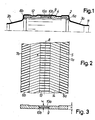
In den Figuren 1, 2 und 3 ist ein Ausführungsbeispiel der erfindungsgemäßen Halterung vereinfacht und schematisch dargestellt,und zwar am Beispiel der Halterung eines katalytisch beschichteten Monolithen in der Abgasleitung eines Fahrzeuges.1, 2 and 3, an exemplary embodiment of the holder according to the invention is shown in simplified and schematic form, using the example of the holder of a catalytically coated monolith in the exhaust pipe of a vehicle.
Es zeigt
- Fig. 1 schematisch einen Längsschnitt der Halterung
- Fig. 2 die Abwicklung des Halteelementes und
- Fig. 3 einen Querschnitt des Halteelementes.
- Fig. 1 shows schematically a longitudinal section of the bracket
- Fig. 2, the handling of the holding element and
- Fig. 3 shows a cross section of the holding element.
Bei dem Ausführungsbeispiel soll ein Körper 1, der ein katalytisch beschichteter Monolith mit einer Vielzahl sehr feiner Längskanäle ist, in einer Rohrleitung 11, im vorliegenden Fall der Abgasleitung eines Fahrzeuges, angeordnet sein und gehalten werden. Es soll ferner die Umströmung des Körpers 1 mit Abgas weitestgehend verhindert werden und die Halterung bei allen Betriebszuständen ausreichend sein. Die Halterung soll trotz der unterschiedlichen Ausdehnungskoeffizienten von Gehäuse (Stahl) und Körper 1 (Keramik) bei den unterschiedlich auftretenden Temperaturen, also bis in einem Bereich von etwa 800° bis 900° C,wirksam sein.In the exemplary embodiment, a body 1, which is a catalytically coated monolith with a large number of very fine longitudinal channels, is intended to be arranged and held in a
Die Abgasleitung 11 weist in Strömungsrichtung einen Einlauftrichter 3a auf, an dem sich das zylindrische Gehäuse anschließt, in welchem der Körper 1 gehalten ist. Das Gehäuse 2 kann an den Einlauftrichter 3a mit größerem Durchmesser angeschlossen sein, so daß sich eine Anlegekante ausbildet. An das Gehäuse 2 schließt sich entsprechend der Auslauftrichter 3b mit der folgenden Rohrleitung an. Das Gehäuse 2 ist mit den beiden Trichtern 3a, 3b entweder verschweißt oder über Flansche verbunden. Das zylindrische Gehäuse 2 hat auf dem Umfang umlaufende Einprägungen 12, die entweder parallel zueinander verlaufen oder spiralförmig eingeprägt sind. Diese Einprägung 12 bewirkt die Verpressung des Halteelementes 4, das den Körper 1 umgibt. Das Halteelement 4 besteht aus einem zu einem ebenen Element zusammengepreßten 2-fädrigen Schlauchgestrick aus Draht von 0,23 mm Durchmesser aus dem Werkstoff Inconel 601 oder Nicrofer 6023 mit einer Gestrickbreite von 95 mm bei 60 Maschen. Das Halteelement 4 hat beiderseits eine pfeilförmige Einprägung 5. Dabei entsteht eine Wellung mit einer Teilung von 10,5 mm bei einer Höhe des Gestrickes von 6,5 mm (Wellung h), der Pfeilverlauf beträgt beiderseitig 72° zur Kante. An beiden Rand bereichen 6a, 6b erfolgt ein Randumschlag an den Längsaußenkanten 7a, 7b von 18 mm, so daß in diesen beiden Bereichen die doppelte Lagenzahl besteht. Ferner ist das Halteelement 4 in einer Längsachse 8 mit einem Abschnitt 9 versehen, in welchem ein Dichtstreifen 10 mit der Dicke d eingelegt ist. Im eingebauten Zustand verläuft diese Längsachse 8 rechtwinklig zur Durchströmrichtung des zu haltenden Katalysators. In dem Abschnitt 9 verlaufen die Fäden 13 des Gestrickes 14 unverformt geradlinig, so daß sie Auflagestege für den oder die Dichtstreifen 10 bzw. 10a, 10b bilden und zur Halterung des Dichtstreifens 10 beitragen, da im Betrieb diese "Stege" 13 sich in die Oberfläche des Dichtstreifens 10 einpressen.
In Fällen besonderer Belastung kann der Dichtstreifen 10 auch mit den geraden Fäden 13 des Gestrickes 14 verwoben werden, so daß jeweils ein Faden 13 oberhalb und der nächstfolgende Faden 13 unterhalb des Dichtstreifens 10 liegt. Damit ist eine besonders gute Lagefixierung des Dichtstreifens 10 in dem Halteelement 4 gegeben. Ein ähnlicher Effekt ergibt sich bei einem schlauchartigen und dann zu einem ebenen Element zusammengepreßten Halteelement 4, wenn der Dichtstreifen 10 vor dem Zusammenpressen in den für den Dichtstreifen 10 vorgesehenen Abschnitt 9 eingelegt wird. In diesem Fall liegt eine Lage der Fäden 13 auf und eine Lage unter dem Dichtstreifen 10.
Der Abschnitt 9 braucht nicht wie in den Figuren dargestellt mittig angeordnet sein, sondern kann auch außermittig in Längsrichtung des Halteelementes 4 verlaufen und zwar parallel zur Längsrichtung oder schräg hierzu.The
In cases of particular stress, the sealing strip 10 can also be interwoven with the
The
Das Halteelement 4 ist breiter als die Länge des Körpers 1, so daß es beim Umhüllen des Körpers 1 an diesen beiden Stirnseiten überragt. Nach dem Zusammenbau legen sich diese über ragenden Abschnitte über die jeweilige stirnseitige Kante des Körpers 1 und bilden sowohl einen Kantenschutz als auch eine erste Abdichtung gegen Umströmung des Körpers 1 durch das Abgas. Durch die pfeilförmigen Einprägungen 5 ergibt sich eine bessere Halterung des Körpers 1 und sie verhindert insbesondere eine Schrägverschiebung des Körpers 1. Ferner ist durch diese Maßnahme eine Unterbrechung des Strömungsweges für das Abgas und damit ebenfalls eine Dichtwirkung gegeben.The holding element 4 is wider than the length of the body 1, so that it protrudes on these two end faces when enveloping the body 1. After assembly, they overlap protruding sections over the respective front edge of the body 1 and form both an edge protection and a first seal against flow around the body 1 by the exhaust gas. The arrow-
Die Fäden 13 des Gestrickes 14 im Abschnitt 9 können alternativ in der Abwicklungsebene der Fig. 2 verformt sein, wobei sie aber nicht aus dieser Ebene herausgebogen sind und daher dort nicht in die Wellgestrickform verformt sind.The
Die Fäden 13 des Gestrickes 14 können in dem Abschnitt 9, anders als in Fig. 1 dargestellt, in einer Fläche unmittelbar anliegend an dem Katalysatorkörper 1 vorgesehen sein. Dann reicht ein Dichtring 10a radial außerhalb des Abschnitts 9 aus. Eine weitere Alternative besteht darin, die Fäden 13 radial außen anliegend an dem Gehäuse 2 vorzusehen, so daß ein radial innerer Dichtring 10b ausreicht.The
Der Dichtstreifen 10 kann entweder zusammen mit der Anbringung des Halteelements 4 oder nachträglich nach Anbringung des Halteelements 4 angebracht werden. Die Möglichkeit des nachträglichen Anbringens besteht auch, wenn das Halteelement 4 durch einfaches oder mehrfaches Herumwickeln um den Katalysatorkörper 1 angebracht wird, insbesondere in der Arbeitsabfolge, daß das Halteelement 4 zunächst etwa zweifach um den Katalysatorkörper 1 herumgewickelt wird und daß erst danach ein Dichtstreifen 10 von außen her in den Abschnitt 9 eingelegt wird. Dabei kann so vorgegangen werden, daß die Fäden 13 durch das Einlegen des Dichtstreifens 10 nach innen an den Katalysatorkörper 1 herangedrückt werden. Dieses Nach-innen-Drücken der Fäden 13 kann auch in dem in Fig. 1 dargestellten Fall stattfinden, bei dem die Fäden 13 an sich radial etwa in der Mitte zwischen dem Katalysatorkörper 1 und dem Gehäuse 2 liegen.The sealing strip 10 can either be attached together with the attachment of the holding element 4 or after the attachment of the holding element 4. The possibility of retrofitting also exists if the holding element 4 is attached to the catalyst body 1 by simply or repeatedly wrapping it around, in particular in the work sequence that the holding element 4 is initially about twice around the Catalyst body 1 is wound around and that only afterwards a sealing strip 10 is inserted from the outside into
Zur Erreichung der doppelten Lagenzahl des Gestrickes 14 an dessen beiden Rändern besteht ferner die Möglichkeit, daß Schlauchgestrick vor dem Flachdrücken an beiden Rändern nach innen einzustülpen und erst dann das Flachdrücken vorzunehmen. Auf diese Weise hat man nicht einen Randumschlag, der radial außen oder radial innen auf dem Halteelement 4 liegt, sondern eine zusammengedrückte Randeinstülpung, bei der das Gestrick 14 am Axialende des Halteelements 4 zunächst um 180° zurückgefaltet ist und in Richtung zur axialen Mitte des Halteelements 4 verläuft, dann wiederum um 180° nach vorn gefaltet ist und zum axialen Rand des Halteelements 4 verläuft, und dann schließlich wiederum um 180° zurückgefaltet ist und so zum anderen Axialende des Halteelements 4 verläuft.In order to achieve double the number of layers of the knitted
Claims (8)
daß in dem der Aufnahme des Dichtstreifens (10) dienenden Abschnitt (9) des Halteelements (4) die metallischen Fäden (13) des Gestricks (14) nicht in die Wellgestrickform verformt sind und in diesem so gebildeten Abschnitt (4) mindestens ein Dichtstreifen (10) eingebracht ist.1. Arrangement for holding a catalytic converter in a housing in the exhaust system of an engine operated with liquid fuel and sealing it against exhaust gas flowing around it by means of a corrugated metallic knitted fabric surrounding the catalytic converter as a holding element, which holds the catalytic converter in its installed position in the housing and at least has a section running in the longitudinal direction of the holding element for receiving a sealing strip, characterized in that
that in the section (9) of the holding element (4) serving to receive the sealing strip (10), the metallic threads (13) of the knitted fabric (14) are not deformed into the corrugated knitted form and in this section (4) thus formed, at least one sealing strip ( 10) is introduced.
dadurch gekennzeichnet,
daß die Wellungseinprägungen (5) des Gestrickes (14) unter einem Winkel zur Katalysatorlängsrichtung verlaufen.4. Arrangement according to one of claims 1 to 3,
characterized,
that the corrugated impressions (5) of the knitted fabric (14) run at an angle to the longitudinal direction of the catalyst.
dadurch gekennzeichnet,
daß nach einem mindestens einlagigen Herumwickeln des Gestrickes (14) um den Katalysator (1) ein Dichtstreifen (10) nachträglich von außen in den Abschnitt (9) eingelegt ist.5. Arrangement according to one of claims 1 to 4,
characterized,
that after the knitted fabric (14) has been wrapped around the catalyst (1) at least in one layer, a sealing strip (10) is subsequently inserted from the outside into the section (9).
dadurch gekennzeichnet,
daß in den beiden Randbereichen (6a, 6b) des Halteelements (4) ein Randumschlag des Gestrickes (14) vorgesehen ist.6. Arrangement according to one of claims 1 to 5,
characterized,
that in the two edge areas (6a, 6b) of the holding element (4) an edge fold of the knitted fabric (14) is provided.
dadurch gekennzeichnekt,
daß das Halteelement (4) aus einem ursprünglich schlauchförmigen und dann zu einer flächigen Gestalt zusammengedrückten Gestrick (14) besteht.7. Arrangement according to one of claims 1 to 6,
characterized by
that the holding element (4) consists of an originally tubular and then compressed into a flat shape knitted fabric (14).
dadurch gekennzeichnet,
daß in den beiden Randbereichen (6a, 6b) des Halteelements (4) das ursprünglich schlauchförmige Gestrick (14) nach innen eingestülpt worden ist, so daß sich dort nach dem Zusammendrücken vierlagige Bereiche ergeben.8. Arrangement according to claim 7,
characterized,
that in the two edge areas (6a, 6b) of the holding element (4) the originally tubular knitted fabric (14) has been turned inwards, so that there are four-layered areas after compression.
Applications Claiming Priority (2)
| Application Number | Priority Date | Filing Date | Title |
|---|---|---|---|
| DE3710299 | 1987-03-28 | ||
| DE19873710299 DE3710299A1 (en) | 1987-03-28 | 1987-03-28 | ARRANGEMENT FOR HOLDING A CATALYST IN A HOUSING IN THE EXHAUST SYSTEM OF A ENGINE USED WITH LIQUID FUEL |
Publications (3)
| Publication Number | Publication Date |
|---|---|
| EP0285027A2 true EP0285027A2 (en) | 1988-10-05 |
| EP0285027A3 EP0285027A3 (en) | 1989-05-10 |
| EP0285027B1 EP0285027B1 (en) | 1992-07-15 |
Family
ID=6324236
Family Applications (1)
| Application Number | Title | Priority Date | Filing Date |
|---|---|---|---|
| EP88104839A Expired - Lifetime EP0285027B1 (en) | 1987-03-28 | 1988-03-25 | Arrangement for mounting a catalyst in a casing in the exhaust system of a liquid fuel engine |
Country Status (5)
| Country | Link |
|---|---|
| US (1) | US4958491A (en) |
| EP (1) | EP0285027B1 (en) |
| CZ (1) | CZ278210B6 (en) |
| DE (3) | DE3710299A1 (en) |
| ES (1) | ES2033968T3 (en) |
Cited By (2)
| Publication number | Priority date | Publication date | Assignee | Title |
|---|---|---|---|---|
| EP0415101B1 (en) * | 1989-09-02 | 1993-09-22 | Leistritz Aktiengesellschaft | Exhaust system, in particular, device for the purification of exhaust gas |
| EP0786585A2 (en) * | 1996-01-26 | 1997-07-30 | Toyota Jidosha Kabushiki Kaisha | Catalytic device for cleaning exhaust gases of an internal combustion engine |
Families Citing this family (9)
| Publication number | Priority date | Publication date | Assignee | Title |
|---|---|---|---|---|
| DE4218198C2 (en) * | 1992-06-03 | 1994-08-18 | Manfred Sagitzki | Catalytic converter housing |
| DE4305198C1 (en) * | 1993-02-19 | 1994-05-11 | Zeuna Staerker Kg | Catalytic exhaust gas cleaning device - has expansible laminate with inner layer gap at interspace between adjacent catalyst bodies |
| SE9301653D0 (en) * | 1993-05-14 | 1993-05-14 | Filterprodukter Ab | CATALYST CARRIER AND APPLICATION OF THIS |
| US6017498A (en) * | 1998-01-14 | 2000-01-25 | Metex Mfg. Corporation | Catalytic converter support device |
| EP1236872B1 (en) * | 2001-02-20 | 2003-12-17 | Zeuna-Stärker Gmbh & Co Kg | Exhaust gas cleaning device |
| FR2825117A1 (en) * | 2001-05-28 | 2002-11-29 | Faurecia Sys Echappement | Exhaust part for exhaust line comprises casing with porous substrate in main section and retaining layer surrounding substrate, internal transverse stops axially support substrate ends |
| US7378060B2 (en) * | 2005-02-04 | 2008-05-27 | Ford Global Technologies, Llc | Support seal for positive retention of catalytic converter substrate and method therefor |
| US11319916B2 (en) | 2016-03-30 | 2022-05-03 | Marine Canada Acquisition Inc. | Vehicle heater and controls therefor |
| US10480387B2 (en) * | 2017-02-08 | 2019-11-19 | Caterpillar Inc. | Housing for aftertreatment systems |
Citations (6)
| Publication number | Priority date | Publication date | Assignee | Title |
|---|---|---|---|---|
| JPS55128613A (en) * | 1979-03-26 | 1980-10-04 | Chuo Spring Co Ltd | Sealing material incorporating cushion for use in single-catalyst type exhaust gas purifying system |
| JPS55164714A (en) * | 1979-06-08 | 1980-12-22 | Mitsubishi Motors Corp | Catalytic converter |
| WO1981000738A1 (en) * | 1979-09-01 | 1981-03-19 | Zeuna Staerker Kg | Device for catalytically purifying exhaust gases from a combustion engine |
| US4500099A (en) * | 1982-06-15 | 1985-02-19 | Toyota Jidosha Kabushiki Kaisha | Elastic supporting and sealing member with thermal foaming strip |
| DE3519965A1 (en) * | 1985-06-04 | 1986-12-04 | Fa. J. Eberspächer, 7300 Esslingen | Arrangement for retention of a body which is arranged in a housing through which gas flows |
| JPS631708A (en) * | 1986-06-23 | 1988-01-06 | Yutaka Giken:Kk | Sealed buffer for catalytic converter |
Family Cites Families (6)
| Publication number | Priority date | Publication date | Assignee | Title |
|---|---|---|---|---|
| US4335077A (en) * | 1972-03-21 | 1982-06-15 | Zeuna-Staerker Kg | Catalyzer for detoxifying exhaust gases from internal combustion engines |
| SE7710455L (en) * | 1976-12-18 | 1978-06-19 | Zeuna Staerker Kg | CATALYTIC CLEANING DEVICE FROM COMBUSTION ENGINES COMING EXHAUST |
| US4343074A (en) * | 1979-10-22 | 1982-08-10 | Uop Inc. | Method of making a catalytic converter |
| DE8019814U1 (en) * | 1980-07-24 | 1980-10-30 | Paul Gillet Gmbh, 6732 Edenkoben | DEVICE FOR STORING CATALYST BLOCKS FOR EXHAUST GAS PURIFICATION IN EXHAUST SYSTEMS FOR COMBUSTION ENGINES |
| JPS5941621A (en) * | 1982-08-31 | 1984-03-07 | Toyota Motor Corp | Monolith catalytic converter |
| US4782661A (en) * | 1987-02-13 | 1988-11-08 | General Motors Corporation | Mat support/substrate subassembly and method of making a catalytic converter therewith |
-
1987
- 1987-03-28 DE DE19873710299 patent/DE3710299A1/en active Granted
- 1987-03-28 DE DE8717839U patent/DE8717839U1/de not_active Expired - Lifetime
-
1988
- 1988-03-25 DE DE8888104839T patent/DE3872743D1/en not_active Expired - Lifetime
- 1988-03-25 EP EP88104839A patent/EP0285027B1/en not_active Expired - Lifetime
- 1988-03-25 ES ES198888104839T patent/ES2033968T3/en not_active Expired - Lifetime
- 1988-03-28 CZ CS882047A patent/CZ278210B6/en unknown
- 1988-03-28 US US07/174,121 patent/US4958491A/en not_active Expired - Fee Related
Patent Citations (6)
| Publication number | Priority date | Publication date | Assignee | Title |
|---|---|---|---|---|
| JPS55128613A (en) * | 1979-03-26 | 1980-10-04 | Chuo Spring Co Ltd | Sealing material incorporating cushion for use in single-catalyst type exhaust gas purifying system |
| JPS55164714A (en) * | 1979-06-08 | 1980-12-22 | Mitsubishi Motors Corp | Catalytic converter |
| WO1981000738A1 (en) * | 1979-09-01 | 1981-03-19 | Zeuna Staerker Kg | Device for catalytically purifying exhaust gases from a combustion engine |
| US4500099A (en) * | 1982-06-15 | 1985-02-19 | Toyota Jidosha Kabushiki Kaisha | Elastic supporting and sealing member with thermal foaming strip |
| DE3519965A1 (en) * | 1985-06-04 | 1986-12-04 | Fa. J. Eberspächer, 7300 Esslingen | Arrangement for retention of a body which is arranged in a housing through which gas flows |
| JPS631708A (en) * | 1986-06-23 | 1988-01-06 | Yutaka Giken:Kk | Sealed buffer for catalytic converter |
Non-Patent Citations (3)
| Title |
|---|
| PATENT ABSTRACTS OF JAPAN, Band 12, Nr. 195 (M-705)[3042], 7. Juni 1988; & JP-A-63 001 708 (YUTAKA GIKEN K.K.) 06-01-1988 * |
| PATENT ABSTRACTS OF JAPAN, Band 4, Nr. 179 (M-46)[661], 11. Dezember 1980; & JP-A-55 128 613 (CHUO HATSUJIYOU K.K.) 04-10-1980 * |
| PATENT ABSTRACTS OF JAPAN, Band 5, Nr. 39 (M-59)[711], 14. März 1981; & JP-A-55 164 714 (MITSUBISHI JIDOSHA KOGYO K.K.) 22-12-1980 * |
Cited By (3)
| Publication number | Priority date | Publication date | Assignee | Title |
|---|---|---|---|---|
| EP0415101B1 (en) * | 1989-09-02 | 1993-09-22 | Leistritz Aktiengesellschaft | Exhaust system, in particular, device for the purification of exhaust gas |
| EP0786585A2 (en) * | 1996-01-26 | 1997-07-30 | Toyota Jidosha Kabushiki Kaisha | Catalytic device for cleaning exhaust gases of an internal combustion engine |
| EP0786585A3 (en) * | 1996-01-26 | 1998-04-08 | Toyota Jidosha Kabushiki Kaisha | Catalytic device for cleaning exhaust gases of an internal combustion engine |
Also Published As
| Publication number | Publication date |
|---|---|
| DE3710299A1 (en) | 1988-10-13 |
| CZ278210B6 (en) | 1993-10-13 |
| ES2033968T3 (en) | 1993-04-01 |
| US4958491A (en) | 1990-09-25 |
| DE3710299C2 (en) | 1990-11-22 |
| DE3872743D1 (en) | 1992-08-20 |
| EP0285027B1 (en) | 1992-07-15 |
| CZ204788A3 (en) | 1993-05-12 |
| DE8717839U1 (en) | 1990-05-31 |
| EP0285027A3 (en) | 1989-05-10 |
Similar Documents
| Publication | Publication Date | Title |
|---|---|---|
| EP0537603B1 (en) | Double-walled air-insulated pipe for exhaust installations in vehicles | |
| DE10358757B4 (en) | Air inlet duct assembly with evaporative emission control | |
| EP0552706A1 (en) | Filtration device for gas stream filtration | |
| EP0285027A2 (en) | Arrangement for mounting a catalyst in a casing in the exhaust system of a liquid fuel engine | |
| EP0471175B1 (en) | Process for manufacturing a device for the catalytic purification or decomposition of hot waste gases | |
| DE2400443A1 (en) | Catalytic exhaust gas cleaner - has catalytic material spaced from cylindrical housing by corrugated steel packing | |
| DE2913732A1 (en) | CATALYTIC CONVERTER FOR EXHAUST GAS PURIFICATION | |
| EP0472009B1 (en) | Exhaust gas purifying device with two exhaust gas treatment bodies one behind the other | |
| DE3922667C2 (en) | Device for catalytic detoxification for deblocking and / or soundproofing of internal combustion engine exhaust gases with a double-walled housing | |
| EP0744537A1 (en) | Exhaust pipe for internal combustion engines | |
| EP0561019B1 (en) | Arrangement for positioning an inner shell in the casing of an exhaust device for vehicles | |
| DE19881673B4 (en) | Catalyst support body with exposed heat radiation surfaces | |
| EP0295444A2 (en) | Pipe connection for a hot fluid conduit | |
| DE3519965C3 (en) | Arrangement for holding a catalyst in a housing of an exhaust system of an engine operated with liquid fuel | |
| DE2341265C2 (en) | Device for catalytic exhaust gas cleaning | |
| EP0758048A1 (en) | Device for catalytically purifying resp. decomposing hot exhaust gases | |
| EP3907383A1 (en) | Exhaust gas heater for an exhaust gas system of a combustion engine | |
| EP0177480B1 (en) | Catalytic off gas purification device | |
| DE2746475A1 (en) | Holder for catalytic exhaust gas purifier housing - has clamping band providing secure support even at high temperatures | |
| DE4109626A1 (en) | MOUNTING A CARRIER BODY IN VEHICLE EXHAUST SYSTEMS | |
| DE19812611C2 (en) | Decoupling element in pipes | |
| DE2407263A1 (en) | Catalytic exhaust gas purifier for motor vehicle engines - has a spring between the catalyst housing and channel walls | |
| DE8115324U1 (en) | EXHAUST WITH CATALYST MONOLITH | |
| DE4427459A1 (en) | IC engine exhaust layout with silencer | |
| WO1999005403A1 (en) | Holding system for a carrier body in a protection tube |
Legal Events
| Date | Code | Title | Description |
|---|---|---|---|
| PUAI | Public reference made under article 153(3) epc to a published international application that has entered the european phase |
Free format text: ORIGINAL CODE: 0009012 |
|
| AK | Designated contracting states |
Kind code of ref document: A2 Designated state(s): DE ES FR GB IT SE |
|
| PUAL | Search report despatched |
Free format text: ORIGINAL CODE: 0009013 |
|
| AK | Designated contracting states |
Kind code of ref document: A3 Designated state(s): DE ES FR GB IT SE |
|
| 17P | Request for examination filed |
Effective date: 19890627 |
|
| 17Q | First examination report despatched |
Effective date: 19891124 |
|
| GRAA | (expected) grant |
Free format text: ORIGINAL CODE: 0009210 |
|
| ITF | It: translation for a ep patent filed |
Owner name: BARZANO' E ZANARDO MILANO S.P.A. |
|
| AK | Designated contracting states |
Kind code of ref document: B1 Designated state(s): DE ES FR GB IT SE |
|
| REF | Corresponds to: |
Ref document number: 3872743 Country of ref document: DE Date of ref document: 19920820 |
|
| GBT | Gb: translation of ep patent filed (gb section 77(6)(a)/1977) | ||
| ET | Fr: translation filed | ||
| REG | Reference to a national code |
Ref country code: ES Ref legal event code: FG2A Ref document number: 2033968 Country of ref document: ES Kind code of ref document: T3 |
|
| PLBE | No opposition filed within time limit |
Free format text: ORIGINAL CODE: 0009261 |
|
| STAA | Information on the status of an ep patent application or granted ep patent |
Free format text: STATUS: NO OPPOSITION FILED WITHIN TIME LIMIT |
|
| 26N | No opposition filed | ||
| EAL | Se: european patent in force in sweden |
Ref document number: 88104839.1 |
|
| REG | Reference to a national code |
Ref country code: ES Ref legal event code: PC2A |
|
| REG | Reference to a national code |
Ref country code: FR Ref legal event code: CD |
|
| PGFP | Annual fee paid to national office [announced via postgrant information from national office to epo] |
Ref country code: ES Payment date: 20010315 Year of fee payment: 14 |
|
| PGFP | Annual fee paid to national office [announced via postgrant information from national office to epo] |
Ref country code: GB Payment date: 20010321 Year of fee payment: 14 |
|
| REG | Reference to a national code |
Ref country code: GB Ref legal event code: IF02 |
|
| PG25 | Lapsed in a contracting state [announced via postgrant information from national office to epo] |
Ref country code: GB Free format text: LAPSE BECAUSE OF NON-PAYMENT OF DUE FEES Effective date: 20020325 |
|
| PG25 | Lapsed in a contracting state [announced via postgrant information from national office to epo] |
Ref country code: ES Free format text: LAPSE BECAUSE OF NON-PAYMENT OF DUE FEES Effective date: 20020326 |
|
| REG | Reference to a national code |
Ref country code: FR Ref legal event code: CJ |
|
| REG | Reference to a national code |
Ref country code: FR Ref legal event code: CJ |
|
| GBPC | Gb: european patent ceased through non-payment of renewal fee |
Effective date: 20020325 |
|
| PGFP | Annual fee paid to national office [announced via postgrant information from national office to epo] |
Ref country code: SE Payment date: 20030225 Year of fee payment: 16 |
|
| REG | Reference to a national code |
Ref country code: ES Ref legal event code: FD2A Effective date: 20030410 |
|
| PG25 | Lapsed in a contracting state [announced via postgrant information from national office to epo] |
Ref country code: SE Free format text: LAPSE BECAUSE OF NON-PAYMENT OF DUE FEES Effective date: 20040326 |
|
| EUG | Se: european patent has lapsed | ||
| PG25 | Lapsed in a contracting state [announced via postgrant information from national office to epo] |
Ref country code: IT Free format text: LAPSE BECAUSE OF NON-PAYMENT OF DUE FEES;WARNING: LAPSES OF ITALIAN PATENTS WITH EFFECTIVE DATE BEFORE 2007 MAY HAVE OCCURRED AT ANY TIME BEFORE 2007. THE CORRECT EFFECTIVE DATE MAY BE DIFFERENT FROM THE ONE RECORDED. Effective date: 20050325 |
|
| PGFP | Annual fee paid to national office [announced via postgrant information from national office to epo] |
Ref country code: DE Payment date: 20070331 Year of fee payment: 20 |
|
| PGFP | Annual fee paid to national office [announced via postgrant information from national office to epo] |
Ref country code: FR Payment date: 20070215 Year of fee payment: 20 |