EP0284894A1 - Dispositif de fixation avec vis et outil à chocs pour fixations universelles - Google Patents
Dispositif de fixation avec vis et outil à chocs pour fixations universelles Download PDFInfo
- Publication number
- EP0284894A1 EP0284894A1 EP88104181A EP88104181A EP0284894A1 EP 0284894 A1 EP0284894 A1 EP 0284894A1 EP 88104181 A EP88104181 A EP 88104181A EP 88104181 A EP88104181 A EP 88104181A EP 0284894 A1 EP0284894 A1 EP 0284894A1
- Authority
- EP
- European Patent Office
- Prior art keywords
- screw
- pulse
- thread
- fastening
- pulse tool
- Prior art date
- Legal status (The legal status is an assumption and is not a legal conclusion. Google has not performed a legal analysis and makes no representation as to the accuracy of the status listed.)
- Granted
Links
- 238000013016 damping Methods 0.000 claims abstract description 7
- 238000000034 method Methods 0.000 claims abstract description 5
- 239000000463 material Substances 0.000 abstract description 10
- 239000004567 concrete Substances 0.000 abstract description 9
- 239000002023 wood Substances 0.000 abstract description 3
- 239000011449 brick Substances 0.000 abstract description 2
- 238000005520 cutting process Methods 0.000 description 6
- 239000004033 plastic Substances 0.000 description 5
- 229920003023 plastic Polymers 0.000 description 5
- 230000000694 effects Effects 0.000 description 4
- 239000002184 metal Substances 0.000 description 4
- 238000003860 storage Methods 0.000 description 3
- 239000012876 carrier material Substances 0.000 description 2
- 238000010276 construction Methods 0.000 description 2
- 238000003780 insertion Methods 0.000 description 2
- 230000037431 insertion Effects 0.000 description 2
- 239000007779 soft material Substances 0.000 description 2
- 230000032683 aging Effects 0.000 description 1
- 230000006835 compression Effects 0.000 description 1
- 238000007906 compression Methods 0.000 description 1
- 230000001419 dependent effect Effects 0.000 description 1
- 238000005553 drilling Methods 0.000 description 1
- 230000008030 elimination Effects 0.000 description 1
- 238000003379 elimination reaction Methods 0.000 description 1
- 239000004519 grease Substances 0.000 description 1
- 238000009499 grossing Methods 0.000 description 1
- 230000003993 interaction Effects 0.000 description 1
- 238000004519 manufacturing process Methods 0.000 description 1
- 238000009527 percussion Methods 0.000 description 1
- 239000011505 plaster Substances 0.000 description 1
- 230000000284 resting effect Effects 0.000 description 1
- 238000010079 rubber tapping Methods 0.000 description 1
- 238000012384 transportation and delivery Methods 0.000 description 1
Images

Classifications
-
- F—MECHANICAL ENGINEERING; LIGHTING; HEATING; WEAPONS; BLASTING
- F16—ENGINEERING ELEMENTS AND UNITS; GENERAL MEASURES FOR PRODUCING AND MAINTAINING EFFECTIVE FUNCTIONING OF MACHINES OR INSTALLATIONS; THERMAL INSULATION IN GENERAL
- F16B—DEVICES FOR FASTENING OR SECURING CONSTRUCTIONAL ELEMENTS OR MACHINE PARTS TOGETHER, e.g. NAILS, BOLTS, CIRCLIPS, CLAMPS, CLIPS OR WEDGES; JOINTS OR JOINTING
- F16B25/00—Screws that cut thread in the body into which they are screwed, e.g. wood screws
- F16B25/0036—Screws that cut thread in the body into which they are screwed, e.g. wood screws characterised by geometric details of the screw
- F16B25/0042—Screws that cut thread in the body into which they are screwed, e.g. wood screws characterised by geometric details of the screw characterised by the geometry of the thread, the thread being a ridge wrapped around the shaft of the screw
- F16B25/0047—Screws that cut thread in the body into which they are screwed, e.g. wood screws characterised by geometric details of the screw characterised by the geometry of the thread, the thread being a ridge wrapped around the shaft of the screw the ridge being characterised by its cross-section in the plane of the shaft axis
-
- B—PERFORMING OPERATIONS; TRANSPORTING
- B25—HAND TOOLS; PORTABLE POWER-DRIVEN TOOLS; MANIPULATORS
- B25B—TOOLS OR BENCH DEVICES NOT OTHERWISE PROVIDED FOR, FOR FASTENING, CONNECTING, DISENGAGING OR HOLDING
- B25B21/00—Portable power-driven screw or nut setting or loosening tools; Attachments for drilling apparatus serving the same purpose
- B25B21/007—Attachments for drilling apparatus for screw or nut setting or loosening
-
- B—PERFORMING OPERATIONS; TRANSPORTING
- B25—HAND TOOLS; PORTABLE POWER-DRIVEN TOOLS; MANIPULATORS
- B25B—TOOLS OR BENCH DEVICES NOT OTHERWISE PROVIDED FOR, FOR FASTENING, CONNECTING, DISENGAGING OR HOLDING
- B25B21/00—Portable power-driven screw or nut setting or loosening tools; Attachments for drilling apparatus serving the same purpose
- B25B21/02—Portable power-driven screw or nut setting or loosening tools; Attachments for drilling apparatus serving the same purpose with means for imparting impact to screwdriver blade or nut socket
-
- F—MECHANICAL ENGINEERING; LIGHTING; HEATING; WEAPONS; BLASTING
- F16—ENGINEERING ELEMENTS AND UNITS; GENERAL MEASURES FOR PRODUCING AND MAINTAINING EFFECTIVE FUNCTIONING OF MACHINES OR INSTALLATIONS; THERMAL INSULATION IN GENERAL
- F16B—DEVICES FOR FASTENING OR SECURING CONSTRUCTIONAL ELEMENTS OR MACHINE PARTS TOGETHER, e.g. NAILS, BOLTS, CIRCLIPS, CLAMPS, CLIPS OR WEDGES; JOINTS OR JOINTING
- F16B25/00—Screws that cut thread in the body into which they are screwed, e.g. wood screws
- F16B25/001—Screws that cut thread in the body into which they are screwed, e.g. wood screws characterised by the material of the body into which the screw is screwed
- F16B25/0026—Screws that cut thread in the body into which they are screwed, e.g. wood screws characterised by the material of the body into which the screw is screwed the material being a hard non-organic material, e.g. stone, concrete or drywall
-
- F—MECHANICAL ENGINEERING; LIGHTING; HEATING; WEAPONS; BLASTING
- F16—ENGINEERING ELEMENTS AND UNITS; GENERAL MEASURES FOR PRODUCING AND MAINTAINING EFFECTIVE FUNCTIONING OF MACHINES OR INSTALLATIONS; THERMAL INSULATION IN GENERAL
- F16B—DEVICES FOR FASTENING OR SECURING CONSTRUCTIONAL ELEMENTS OR MACHINE PARTS TOGETHER, e.g. NAILS, BOLTS, CIRCLIPS, CLAMPS, CLIPS OR WEDGES; JOINTS OR JOINTING
- F16B25/00—Screws that cut thread in the body into which they are screwed, e.g. wood screws
- F16B25/10—Screws performing an additional function to thread-forming, e.g. drill screws or self-piercing screws
- F16B25/103—Screws performing an additional function to thread-forming, e.g. drill screws or self-piercing screws by means of a drilling screw-point, i.e. with a cutting and material removing action
Definitions
- the invention relates to a fastening device according to the preamble of the first claim.
- Wood screws were used on wooden walls and beams, plastic or metal dowels with screws on concrete walls, and other fasteners were often used in walls made of brick, plaster and wooden panels, etc. This means that a whole range of different fasteners were required, which had to be kept in stock and taken away. In addition, different dimensions were required not only for screws of different sizes, but also for the dowels, which in turn made storage difficult and required additional transport capacity.
- an anchorless attachment is striven to avoid the relatively easy to damage attachment type associated with the anchors and the associated storage.
- the solution according to the invention greatly reduces both the storage and the amount of fastening parts to be carried to a construction site, the omitted dowels contributing to this.
- the reduced inventory in particular, greatly reduces costs. Furthermore, the transport problem for deliveries to construction sites is simplified.
- FIG. 1 shows a fastening device consisting of a pulse tool 1 and a screw 2.
- a metal washer 3 and a damping element 4 are mounted on the screw, the washer 3 being connected in one piece to the screw 2, and the damping element 4 being made of rubber and non-positively resting on the thread 5 of the screw 2.
- the cutting edge of the thread 5 is very sharp to facilitate the turning process, especially in concrete.
- Fig. 2 shows a partial section through a concrete wall 6 along the axis of a screw 2 inserted therein, which is used here, for example, for fastening a metal strip 7 to the wall 6. So that the insertion of the screw 2 is facilitated, a free space 8 is provided between the screw 2 and the inner wall 9 of a borehole 10. This space 8 is used to hold material that is transported with the screw 2 to the interior of the borehole 10.
- the free space 8 can be partially produced by slightly compressing the front part of the screw 2 on opposite sides 11 and 12, as shown in FIGS. 1 and 3. The compression facilitates the insertion of the screw into the borehole 10 in the concrete wall 6 and produces a cutting effect.
- the pulse tool 1 consists of a drive part 14 and a driven part 15 and is driven on a shaft 13 by a conventional hand drill or hand screwdriver, which is designed accordingly for screw fastening.
- This machine transmits a percussion pulse to a body 23 in the driven part 15 via a body 22 in the drive part 14, which bodies 22, 23 are dimensioned such that the resulting force or the impact pulse has a direction corresponding to the thread course.
- the greatest possible effect of the impact force is transferred to the rotary movement of the screw 2.
- the impact pulse is transmitted to the screw 2 only when the drive part 14 runs clockwise. When running counterclockwise, the drive part 14 does not transmit any impact impulses to the screw 2.
- the two bodies 22, 23 each rotate with the drive part 14 or the driven part 15 about an axis 16, along which a shaft 17 of the driven element 15 extends, which is surrounded by a sleeve 18.
- the two parts 14 and 15 are held together by a cylindrical pin 19 which is inserted into a bore 20 in the drive part 14 and engages in a recess in 21 of the shaft 17.
- the cylinder pin 19 is held by a spring ring 29.
- connection between the drive part 14 and the driven part 15 is designed because of the recess 21 such that a free rotary movement of the parts 14, 15 relative to one another is possible without engagement.
- the impact pulses are transmitted through a socket 26 to the hexagon head 26 of the screw 2.
- the lengths of the parallel cutting edges are dimensioned such that they run outwards within the conical secondary tip 27, just before they have reached the largest diameter.
- the subsequent, conically tapering tips (without cutting) have a smooth effect in the removed recesses in the surface.
- the primary tip 28 In front of the smallest diameter of the conical secondary tip 27 is the primary tip 28, which takes over the function as a centering device during the cutting process and additionally takes over the function of the drill in soft materials, in which it is not necessary to pre-drill.
- the screwing process can be controlled by the speed and the pressure on the pulse tool.
- the energy of the pulse beats increases with increasing speed. This gradually creates a helical cut, which adapts to the contour of the screw 2 without play.
- the screwing-in process is ended when the damping element 4 rests on the part 7 to be fastened, which is located in front of the integrated support surface 3 below.
- the damping element 4 is compressed, so that on the one hand the radial friction increases and the pulse beat is thus damped.
- the screw 2 can therefore not be tightened.
- screw 2 can be screwed in and then unscrewed again. Disassembly can be carried out with a pulse tool with left-hand gear or with a wrench. The screwing in and unscrewing can be repeated a few or several times, depending on the material, without the screw 2 having to be replaced by a version with larger dimensions.
- a hole 10 In order to insert the screw 2 in a wall 6, a hole 10 generally has to be drilled first, but this is not absolutely necessary if it is a soft material, for example certain types of wood.
- the diameter of the hole 10 always corresponds to the shaft diameter of the screw 2.
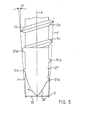
- the screw tip shows an exemplary embodiment of the screw tip with the primary tip 28 der and the secondary tip 27,, the lateral surface F intersecting the elongated shaft sleeve H at tip height S.
- the inclination between the lateral surface F and the screw axis A is approximately 5 °.
- this angle can be both smaller and larger and can be, for example, in the range from 2 to 10 °.
- the front part of the thread from 31a to 31d which is provided with a sharp edge in the lateral surface, serves to loosen the material, so that the subsequent thread 5a to 5c to a certain extent exert a smoothing effect in the internal thread of the hole wall and therein can get stuck.
- the screw can either have two or only one thread.
- the two-threaded version usually offers a firmer grip, whereas the one-threaded version is cheaper to manufacture. It is therefore largely a cost-effective consideration which of the two versions is used, with the specific application also playing a role.
Landscapes
- Engineering & Computer Science (AREA)
- General Engineering & Computer Science (AREA)
- Mechanical Engineering (AREA)
- Physics & Mathematics (AREA)
- Geometry (AREA)
- Connection Of Plates (AREA)
- Joining Of Building Structures In Genera (AREA)
- Details Of Spanners, Wrenches, And Screw Drivers And Accessories (AREA)
- Gripping Jigs, Holding Jigs, And Positioning Jigs (AREA)
- Percussive Tools And Related Accessories (AREA)
Priority Applications (1)
| Application Number | Priority Date | Filing Date | Title |
|---|---|---|---|
| AT88104181T ATE95104T1 (de) | 1987-03-24 | 1988-03-16 | Befestigungseinrichtung mit schraube und impulswerkzeug fuer universelle befestigungen. |
Applications Claiming Priority (2)
| Application Number | Priority Date | Filing Date | Title |
|---|---|---|---|
| CH1109/87 | 1987-03-24 | ||
| CH1109/87A CH672822A5 (fr) | 1987-03-24 | 1987-03-24 |
Publications (2)
| Publication Number | Publication Date |
|---|---|
| EP0284894A1 true EP0284894A1 (fr) | 1988-10-05 |
| EP0284894B1 EP0284894B1 (fr) | 1993-09-29 |
Family
ID=4202697
Family Applications (1)
| Application Number | Title | Priority Date | Filing Date |
|---|---|---|---|
| EP88104181A Expired - Lifetime EP0284894B1 (fr) | 1987-03-24 | 1988-03-16 | Dispositif de fixation avec vis et outil à chocs pour fixations universelles |
Country Status (7)
| Country | Link |
|---|---|
| US (1) | US4936395A (fr) |
| EP (1) | EP0284894B1 (fr) |
| JP (2) | JPS63256374A (fr) |
| AT (1) | ATE95104T1 (fr) |
| CH (1) | CH672822A5 (fr) |
| DE (1) | DE3884437D1 (fr) |
| ES (1) | ES2043703T3 (fr) |
Cited By (3)
| Publication number | Priority date | Publication date | Assignee | Title |
|---|---|---|---|---|
| EP0394604A2 (fr) * | 1989-04-22 | 1990-10-31 | ITW-ATECO GmbH | Procédé et dispositif pour former un filetage dans la pierre ou le béton |
| EP3543551A1 (fr) * | 2018-03-20 | 2019-09-25 | SFS Intec Holding AG | Élément de fixation d'espace destiné à fixer un cadre dans un intrados |
| EP3825064A1 (fr) * | 2019-11-21 | 2021-05-26 | fischerwerke GmbH & Co. KG | Procédé de vissage d'une vis à béton autotaranteuse |
Families Citing this family (4)
| Publication number | Priority date | Publication date | Assignee | Title |
|---|---|---|---|---|
| DE19938363A1 (de) * | 1999-08-13 | 2001-02-15 | Hilti Ag | Schraubanker |
| US6487940B2 (en) | 2001-01-23 | 2002-12-03 | Associated Toolmakers Incorporated | Nut driver |
| US10570943B2 (en) * | 2016-11-16 | 2020-02-25 | Illinois Tool Works Inc. | Threaded fastener |
| US11692578B2 (en) | 2018-09-26 | 2023-07-04 | Illinois Tool Works Inc. | Post-to-beam fastener |
Citations (6)
| Publication number | Priority date | Publication date | Assignee | Title |
|---|---|---|---|---|
| US2143173A (en) * | 1935-03-09 | 1939-01-10 | William H Keller Inc | Rotary driving tool |
| GB1292537A (en) * | 1969-12-13 | 1972-10-11 | Bosch Gmbh Robert | Improvements in or relating to hand power tools |
| DE2427352A1 (de) * | 1974-06-06 | 1975-12-18 | Ulrich Schmidt | Vorsatzschraubendreher |
| DE2521555A1 (de) * | 1974-12-23 | 1976-07-01 | Illinois Tool Works | Mauerwerk-ankervorrichtung |
| DE2929179A1 (de) * | 1978-07-20 | 1980-01-31 | Illinois Tool Works | Bohrschraube aus rostfreiem stahl und verfahren zu deren herstellung |
| AT380545B (de) * | 1984-05-25 | 1986-06-10 | Sfs Stadler Ag | Schraube |
Family Cites Families (5)
| Publication number | Priority date | Publication date | Assignee | Title |
|---|---|---|---|---|
| US1954620A (en) * | 1932-04-25 | 1934-04-10 | Edwin L Connell | Clutch |
| US2126673A (en) * | 1937-06-10 | 1938-08-09 | Buckeye Portable Tool Company | Portable power operated tool |
| US2724299A (en) * | 1953-11-06 | 1955-11-22 | Chicago Pneumatic Tool Co | Torque control clutch device for threaded fastener setting tools |
| US3319723A (en) * | 1965-04-01 | 1967-05-16 | Ingersoll Rand Co | Axial piston pulse generator |
| EP0102605B1 (fr) * | 1982-09-02 | 1986-08-13 | Rockenfeller KG Befestigungselemente | Vis à bois |
-
1987
- 1987-03-24 CH CH1109/87A patent/CH672822A5/de not_active IP Right Cessation
-
1988
- 1988-03-16 AT AT88104181T patent/ATE95104T1/de not_active IP Right Cessation
- 1988-03-16 EP EP88104181A patent/EP0284894B1/fr not_active Expired - Lifetime
- 1988-03-16 ES ES88104181T patent/ES2043703T3/es not_active Expired - Lifetime
- 1988-03-16 DE DE88104181T patent/DE3884437D1/de not_active Expired - Lifetime
- 1988-03-18 US US07/169,673 patent/US4936395A/en not_active Expired - Lifetime
- 1988-03-18 JP JP63063756A patent/JPS63256374A/ja active Pending
-
1995
- 1995-03-17 JP JP002065U patent/JPH0744686U/ja active Pending
Patent Citations (6)
| Publication number | Priority date | Publication date | Assignee | Title |
|---|---|---|---|---|
| US2143173A (en) * | 1935-03-09 | 1939-01-10 | William H Keller Inc | Rotary driving tool |
| GB1292537A (en) * | 1969-12-13 | 1972-10-11 | Bosch Gmbh Robert | Improvements in or relating to hand power tools |
| DE2427352A1 (de) * | 1974-06-06 | 1975-12-18 | Ulrich Schmidt | Vorsatzschraubendreher |
| DE2521555A1 (de) * | 1974-12-23 | 1976-07-01 | Illinois Tool Works | Mauerwerk-ankervorrichtung |
| DE2929179A1 (de) * | 1978-07-20 | 1980-01-31 | Illinois Tool Works | Bohrschraube aus rostfreiem stahl und verfahren zu deren herstellung |
| AT380545B (de) * | 1984-05-25 | 1986-06-10 | Sfs Stadler Ag | Schraube |
Cited By (4)
| Publication number | Priority date | Publication date | Assignee | Title |
|---|---|---|---|---|
| EP0394604A2 (fr) * | 1989-04-22 | 1990-10-31 | ITW-ATECO GmbH | Procédé et dispositif pour former un filetage dans la pierre ou le béton |
| EP0394604A3 (fr) * | 1989-04-22 | 1991-08-21 | ITW-ATECO GmbH | Procédé et dispositif pour former un filetage dans la pierre ou le béton |
| EP3543551A1 (fr) * | 2018-03-20 | 2019-09-25 | SFS Intec Holding AG | Élément de fixation d'espace destiné à fixer un cadre dans un intrados |
| EP3825064A1 (fr) * | 2019-11-21 | 2021-05-26 | fischerwerke GmbH & Co. KG | Procédé de vissage d'une vis à béton autotaranteuse |
Also Published As
| Publication number | Publication date |
|---|---|
| ES2043703T3 (es) | 1994-01-01 |
| JPH0744686U (ja) | 1995-11-28 |
| US4936395A (en) | 1990-06-26 |
| DE3884437D1 (de) | 1993-11-04 |
| JPS63256374A (ja) | 1988-10-24 |
| ATE95104T1 (de) | 1993-10-15 |
| CH672822A5 (fr) | 1989-12-29 |
| EP0284894B1 (fr) | 1993-09-29 |
Similar Documents
| Publication | Publication Date | Title |
|---|---|---|
| DE60124046T2 (de) | Mauerwerkanker mit selbstschneidendem Gewinde | |
| EP0102605B1 (fr) | Vis à bois | |
| EP0697071B1 (fr) | Vis a former les filetages | |
| DE69917588T2 (de) | Verankerungsdübel für sprödes Material | |
| EP0623759A1 (fr) | Vis autotaraudeuse | |
| EP0894202B1 (fr) | Vis de fixation de profiles ou de plaques en metal et/ou en plastique sur une base | |
| EP1305529B1 (fr) | Cheville pour materiaux legers, et utilisation d'un embout de tournevis pour visser une telle cheville | |
| EP0314950B1 (fr) | Vis d'écartement | |
| EP1907714A1 (fr) | Ancre pour beton formant un filetage | |
| EP0824198A1 (fr) | Vis ayant une pointe autoperçante | |
| EP0284894B1 (fr) | Dispositif de fixation avec vis et outil à chocs pour fixations universelles | |
| EP0874165A1 (fr) | Dispositif de fixation murale | |
| DE3914881A1 (de) | Montageeinheit mit einem spreizanker und einem montagewerkzeug | |
| DE1960453A1 (de) | Holzschraube und Verfahren zu deren Herstellung | |
| EP1085220A2 (fr) | Boulon d'ancrage | |
| EP0394604A2 (fr) | Procédé et dispositif pour former un filetage dans la pierre ou le béton | |
| CH660774A5 (en) | Spacer screw | |
| EP2039845B1 (fr) | Elément de fixation pour la fixation de plaques de matériau isolant sur un sous-sol | |
| EP1193407B1 (fr) | Vis d'ecartement | |
| EP0470470A2 (fr) | Cheville avec un manchon à cheville | |
| DE19506081A1 (de) | Befestigungselement | |
| CH687746A5 (de) | Werkzeug zum Einbringen eines mit Aussengewinde versehenen Befestigungselementes in Baumaterial. | |
| DE4108332C1 (fr) | ||
| EP0432397A2 (fr) | Dispositif de démontage | |
| EP0055425B1 (fr) | Dispositif pour attacher des éléments de construction à maçonnerie ou analogue |
Legal Events
| Date | Code | Title | Description |
|---|---|---|---|
| PUAI | Public reference made under article 153(3) epc to a published international application that has entered the european phase |
Free format text: ORIGINAL CODE: 0009012 |
|
| AK | Designated contracting states |
Kind code of ref document: A1 Designated state(s): AT BE CH DE ES FR GB GR IT LI LU NL SE |
|
| 17P | Request for examination filed |
Effective date: 19890121 |
|
| 17Q | First examination report despatched |
Effective date: 19900126 |
|
| GRAA | (expected) grant |
Free format text: ORIGINAL CODE: 0009210 |
|
| ITF | It: translation for a ep patent filed |
Owner name: BARZANO' E ZANARDO MILA |
|
| AK | Designated contracting states |
Kind code of ref document: B1 Designated state(s): AT BE CH DE ES FR GB GR IT LI LU NL SE |
|
| REF | Corresponds to: |
Ref document number: 95104 Country of ref document: AT Date of ref document: 19931015 Kind code of ref document: T |
|
| REF | Corresponds to: |
Ref document number: 3884437 Country of ref document: DE Date of ref document: 19931104 |
|
| ET | Fr: translation filed | ||
| GBT | Gb: translation of ep patent filed (gb section 77(6)(a)/1977) |
Effective date: 19931101 |
|
| REG | Reference to a national code |
Ref country code: ES Ref legal event code: FG2A Ref document number: 2043703 Country of ref document: ES Kind code of ref document: T3 |
|
| REG | Reference to a national code |
Ref country code: GR Ref legal event code: FG4A Free format text: 3010220 |
|
| PG25 | Lapsed in a contracting state [announced via postgrant information from national office to epo] |
Ref country code: LU Free format text: LAPSE BECAUSE OF NON-PAYMENT OF DUE FEES Effective date: 19940331 |
|
| PLBE | No opposition filed within time limit |
Free format text: ORIGINAL CODE: 0009261 |
|
| STAA | Information on the status of an ep patent application or granted ep patent |
Free format text: STATUS: NO OPPOSITION FILED WITHIN TIME LIMIT |
|
| 26N | No opposition filed | ||
| PGFP | Annual fee paid to national office [announced via postgrant information from national office to epo] |
Ref country code: GR Payment date: 19941130 Year of fee payment: 8 |
|
| EAL | Se: european patent in force in sweden |
Ref document number: 88104181.8 |
|
| PG25 | Lapsed in a contracting state [announced via postgrant information from national office to epo] |
Ref country code: GR Free format text: THE PATENT HAS BEEN ANNULLED BY A DECISION OF A NATIONAL AUTHORITY Effective date: 19960930 |
|
| REG | Reference to a national code |
Ref country code: GR Ref legal event code: MM2A Free format text: 3010220 |
|
| REG | Reference to a national code |
Ref country code: CH Ref legal event code: PUE Owner name: PAT AG TRANSFER- HILTI AKTIENGESELLSCHAFT |
|
| REG | Reference to a national code |
Ref country code: GB Ref legal event code: 732E |
|
| REG | Reference to a national code |
Ref country code: FR Ref legal event code: TP |
|
| NLS | Nl: assignments of ep-patents |
Owner name: HILTI AKTIENGESELLSCHAFT |
|
| REG | Reference to a national code |
Ref country code: ES Ref legal event code: PC2A |
|
| REG | Reference to a national code |
Ref country code: GB Ref legal event code: IF02 |
|
| PGFP | Annual fee paid to national office [announced via postgrant information from national office to epo] |
Ref country code: ES Payment date: 20050425 Year of fee payment: 18 |
|
| PGFP | Annual fee paid to national office [announced via postgrant information from national office to epo] |
Ref country code: BE Payment date: 20050509 Year of fee payment: 18 |
|
| PG25 | Lapsed in a contracting state [announced via postgrant information from national office to epo] |
Ref country code: ES Free format text: LAPSE BECAUSE OF NON-PAYMENT OF DUE FEES Effective date: 20060317 |
|
| PG25 | Lapsed in a contracting state [announced via postgrant information from national office to epo] |
Ref country code: BE Free format text: LAPSE BECAUSE OF NON-PAYMENT OF DUE FEES Effective date: 20060331 |
|
| PGFP | Annual fee paid to national office [announced via postgrant information from national office to epo] |
Ref country code: IT Payment date: 20060331 Year of fee payment: 19 |
|
| PGFP | Annual fee paid to national office [announced via postgrant information from national office to epo] |
Ref country code: DE Payment date: 20070222 Year of fee payment: 20 |
|
| PGFP | Annual fee paid to national office [announced via postgrant information from national office to epo] |
Ref country code: NL Payment date: 20070304 Year of fee payment: 20 |
|
| PGFP | Annual fee paid to national office [announced via postgrant information from national office to epo] |
Ref country code: SE Payment date: 20070307 Year of fee payment: 20 |
|
| PGFP | Annual fee paid to national office [announced via postgrant information from national office to epo] |
Ref country code: AT Payment date: 20070313 Year of fee payment: 20 |
|
| PGFP | Annual fee paid to national office [announced via postgrant information from national office to epo] |
Ref country code: GB Payment date: 20070314 Year of fee payment: 20 Ref country code: CH Payment date: 20070314 Year of fee payment: 20 |
|
| REG | Reference to a national code |
Ref country code: ES Ref legal event code: FD2A Effective date: 20060317 |
|
| BERE | Be: lapsed |
Owner name: *HILTI A.G. Effective date: 20060331 |
|
| REG | Reference to a national code |
Ref country code: GB Ref legal event code: PE20 Expiry date: 20080315 |
|
| REG | Reference to a national code |
Ref country code: CH Ref legal event code: PL |
|
| PG25 | Lapsed in a contracting state [announced via postgrant information from national office to epo] |
Ref country code: NL Free format text: LAPSE BECAUSE OF EXPIRATION OF PROTECTION Effective date: 20080316 |
|
| PGFP | Annual fee paid to national office [announced via postgrant information from national office to epo] |
Ref country code: FR Payment date: 20070308 Year of fee payment: 20 |
|
| NLV7 | Nl: ceased due to reaching the maximum lifetime of a patent |
Effective date: 20080316 |
|
| EUG | Se: european patent has lapsed | ||
| PG25 | Lapsed in a contracting state [announced via postgrant information from national office to epo] |
Ref country code: GB Free format text: LAPSE BECAUSE OF EXPIRATION OF PROTECTION Effective date: 20080315 |
|
| PG25 | Lapsed in a contracting state [announced via postgrant information from national office to epo] |
Ref country code: IT Free format text: LAPSE BECAUSE OF NON-PAYMENT OF DUE FEES Effective date: 20070316 |