EP0284841B1 - Verfahren und Vorrichtung zum Beladen und Entladen einer Werkzeugausrüstung in einer Giessereimaschine - Google Patents
Verfahren und Vorrichtung zum Beladen und Entladen einer Werkzeugausrüstung in einer Giessereimaschine Download PDFInfo
- Publication number
- EP0284841B1 EP0284841B1 EP88103618A EP88103618A EP0284841B1 EP 0284841 B1 EP0284841 B1 EP 0284841B1 EP 88103618 A EP88103618 A EP 88103618A EP 88103618 A EP88103618 A EP 88103618A EP 0284841 B1 EP0284841 B1 EP 0284841B1
- Authority
- EP
- European Patent Office
- Prior art keywords
- tooling
- mainframe
- ejecting
- loading
- removal
- Prior art date
- Legal status (The legal status is an assumption and is not a legal conclusion. Google has not performed a legal analysis and makes no representation as to the accuracy of the status listed.)
- Expired
Links
- 238000000034 method Methods 0.000 title description 8
- 230000015572 biosynthetic process Effects 0.000 claims description 5
- 239000012778 molding material Substances 0.000 claims description 3
- 239000004576 sand Substances 0.000 description 37
- 230000007246 mechanism Effects 0.000 description 30
- 230000008878 coupling Effects 0.000 description 7
- 238000010168 coupling process Methods 0.000 description 7
- 238000005859 coupling reaction Methods 0.000 description 7
- 239000006096 absorbing agent Substances 0.000 description 5
- 238000010276 construction Methods 0.000 description 5
- 230000035939 shock Effects 0.000 description 5
- 230000008901 benefit Effects 0.000 description 4
- 238000005755 formation reaction Methods 0.000 description 4
- 238000007664 blowing Methods 0.000 description 3
- 230000006835 compression Effects 0.000 description 3
- 238000007906 compression Methods 0.000 description 3
- 239000011230 binding agent Substances 0.000 description 2
- 238000010586 diagram Methods 0.000 description 2
- 238000004519 manufacturing process Methods 0.000 description 2
- 230000000717 retained effect Effects 0.000 description 2
- 238000007789 sealing Methods 0.000 description 2
- 238000000926 separation method Methods 0.000 description 2
- 230000009471 action Effects 0.000 description 1
- 238000005266 casting Methods 0.000 description 1
- 238000004891 communication Methods 0.000 description 1
- 238000012423 maintenance Methods 0.000 description 1
- 238000000465 moulding Methods 0.000 description 1
- 230000002028 premature Effects 0.000 description 1
- 230000008569 process Effects 0.000 description 1
- 238000010926 purge Methods 0.000 description 1
- 230000003252 repetitive effect Effects 0.000 description 1
- 230000002441 reversible effect Effects 0.000 description 1
- 230000006641 stabilisation Effects 0.000 description 1
- 238000011105 stabilization Methods 0.000 description 1
- 230000032258 transport Effects 0.000 description 1
Images


Classifications
-
- B—PERFORMING OPERATIONS; TRANSPORTING
- B22—CASTING; POWDER METALLURGY
- B22C—FOUNDRY MOULDING
- B22C9/00—Moulds or cores; Moulding processes
- B22C9/12—Treating moulds or cores, e.g. drying, hardening
- B22C9/123—Gas-hardening
-
- B—PERFORMING OPERATIONS; TRANSPORTING
- B22—CASTING; POWDER METALLURGY
- B22C—FOUNDRY MOULDING
- B22C15/00—Moulding machines characterised by the compacting mechanism; Accessories therefor
- B22C15/23—Compacting by gas pressure or vacuum
- B22C15/24—Compacting by gas pressure or vacuum involving blowing devices in which the mould material is supplied in the form of loose particles
Definitions
- This invention relates to a foundry machine for forming molds or cores by an automated process.
- the table is adapted to lift the stacked mold boxes into communication with the underside of the blow plate for filling or charging the mold box cavity with sand, following which the mold boxes are lowered and curing means, such as a catalyzing gas manifold, are transferred into engagement with the lowered mold boxes to inject a sand-curing gas into the mold cavity. Following this step, means are provided for vertically separating the upper and lower mold boxes, ejecting the newly-formed part and automatically conveying the part away.
- curing means such as a catalyzing gas manifold
- the above-mentioned prior art Goss patent describes a variety of techniques which have been employed for ejecting the finished part from the mold boxes.
- One of the methods involves separating the molds and then inverting the mold box which initially retained the finished part and ejecting the part downwardly from the inverted box onto a transfer device.
- Another technique therein described involves separating the mold boxes, moving the finished part upwardly out of the lower mold box on ejector pins, moving a fork transversely into the space between the lower mold box and temporarily elevated part, and then lowering the ejector pins to deposit the part onto the fork, which can then be transversely withdrawn.
- Still another disclosed technique involves separating the molds while retaining the formed part in the upper mold half, transversely moving a conveyor or fork-type device into the space beneath the downwardly-facing upper mold cavity and ejecting the part downwardly onto the conveyor for removal.
- associated tooling unique to a given finished part may include, in addition to the cope and drag, an underlying bottom stool containing a lower ejector mechanism, an upper ejector mechanism, a gassing manifold, a blow plate and a sand magazine. It would be highly desirable to further automate the operating cycle by providing means for automatically loading such additional associated tooling into the foundry machine, without the need for manual placement or securing of these components.
- the mainframe of the foundry machine is provided with a work table which supports the tooling during portions of the operating cycle and additional tooling support means which support the tooling during other portions of the cycle.
- additional tooling support means include means for separating the upper and lower mold boxes following formation of a part within the mold box cavities.
- a stationary tooling loading table is provided adjacent to the mainframe and work table, and includes tooling transfer means for moving the tooling to and from the additional tooling support means mounted in the mainframe. Part-removal means are also provided for removing a finished part which has been ejected from the separated molds.
- the tooling is conveyed along rails on the auxiliary table and then onto aligned rails which form a portion of the additional tooling support means in the mainframe.
- the work table then lifts the tooling off of such mainframe rails, and these rails are swung into an inactive position where they avoid interference with the vertically moving table and tooling.
- a further advantage concernes the mounting of the part-removal means on the auxiliary table, and the use of the same transfer means to both load and unload the tooling from the mainframe and to remove a completed part by means of the part removal means.
- Another advantage of this invention is the use of only a single transfer mechanism to propel both the tool-loading and unloading means and the part removal means, thereby saving expense, maintenance and space.
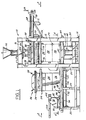
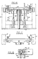
- the improved core-making machine of this invention comprises a mainframe 10 which includes four posts 12 interconnecting base plate 14 and horizontal upper beams 16.
- Tooling 24 comprises a series of stacked components including bottom stool 26, lower core box or drag 28, upper core box or cope 30, gassing manifold and ejector plate 32, blow plate 34 and sand magazine 36.
- Drag 28 and cope 30 contain cavities (not illustrated) for the core which is to be formed.
- Bottom stool 26 is provided with wheels 38 that permit the tooling to roll along rails 22 and onto pivotable rails 40 which are aligned with rails 22 and pivotally secured to mainframe 10.
- Rails 40 are adapted to pivot out of the path of vertically moving clamping table 42 by means of hydraulic rotary actuators 44.
- FIGURE 1 illustrates tooling 24 in its initial position on tool-loading and pick-off table 18, and also shows in phantom the tooling in position on rails 40 of mainframe 10 after it has been automatically moved into such position by the mechanism to be described below.
- FIGURES 1 and 3 Also illustrated in FIGURES 1 and 3 is the telescoping table clamp cylinder 46 which functions to raise and lower tool clamping table 42.
- the lower end of cylinder 46 is fixed to base 14, while the extendable outer cylinder sleeve is secured to the underside of table 42.
- sand is loaded into the system by means of sand hopper 52 which interconnects with blow plate 34 and sand magazine 36 by means of blow sleeve 54.
- the flow of sand which generally includes a binder, is controlled by a butterfly valve (not illustrated) and hopper valve actuator 56, while air is permitted to escape during the sand charging operation by means of sand magazine exhaust vent valves 58 and exhaust valve 60.
- Blowing air is supplied from pressurized air tank 62 under the control of blow valve control 64.
- FIGURES 1 and 3 also illustrate a mechanism for transferring the gassing manifold and ejector plate 32 between its operating and stand-by positions.
- a support frame 66 mounted on mainframe 10 carries a pair of hydraulic cylinders 68 which are connected to a transfer carriage 70 from which depend hanger brackets 72 and 73 which engage retainer brackets 74 on gassing manifold and ejector plate 32. Further details of the construction and operation of this transfer mechanism will be discussed below.
- FIGURES 2 and 3 also illustrate a series of cope hangers 76 which are pivotally mounted on frame crossmember 174 under the control of hydraulic cylinders 176 and which function to support the upper core box or cope during certain phases of the machine cycle.
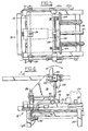
- FIGURES 1 and 2 also illustrate a trolley and carriage mechanism which functions both to transfer tooling 24 into and out of the work station of mainframe 10 and also to pick off and remove the completed core from the tooling.
- Trolley 78 has wheels 80 which ride along tracks 22.
- Trolley 78 engages a horizontally movable carriage 82 for movement therewith by means of latch 84 and latch pin 86.
- Carriage 82 is supported for horizontal movement by means of guide supports 88, while movement of the carriage and trolley is controlled by a hydraulic transfer cylinder 90 operating through cable 92 and its connection 94 to the carriage.
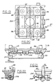
- FIGURE 4 which shows tooling 24 in phantom (in both of its positions) and omits trolley 78 for clarity, shows gripper jaws 96 which form a portion of carriage 82 and which are adapted to releasably engage and grip coupling 98 which forms a portion of bottom stool 26 of tooling 24.
- the actuation means for jaws 96 will be further described below.
- FIGURES 1 and 2 also illustrate pick-off unit 100 which is pivotally mounted on trolley 78 under the control of hydraulic rotary actuator 102. As will be further explained below, pick-off unit 100 may be pivoted from its illustrated retracted position to an extended condition wherein it removes a completed and ejected core from the core boxes and transports the core out of the work station within mainframe 10.
- FIGURES 5 and 6 show further details of trolley 78 and pick-off unit 100.
- the fingers of the pick-off unit have been omitted for clarity.
- the fingers are adapted to be secured to mounting plates 104, which are in turn secured to bracket 106 which is clamped to pick-off finger pivot shaft 108.
- Pivot shaft 108 is selectively rotatable through approximately 180 degrees under the control of rotary actuator 102.
- trolley 78 is provided with downwardly extending hold-down brackets 110, on the lower end of which are secured rollers 112 which engage the lower face of rails 22. These rollers stabilize the trolley and prevent it from tipping, particularly when the pick-off fingers are supporting a completed core.
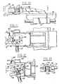
- FIGURE 7 shows additional details of the carriage and trolley.
- Previously mentioned carriage guide supports 88 support longitudinally extending carriage guide rods 114.
- Carriage 82 is provided with bushings 116 which engage and slidably grip guide rods 114. In this manner, carriage 82 is supported and guided during its longitudinal movement toward and away from mainframe 10.
- FIGURE 7 also illustrates hydraulic cylinder 118 which controls the opening and closing of gripper jaws 96 on carriage 82.
- hydraulic cylinder 118 controls the opening and closing of gripper jaws 96 on carriage 82.
- rail 22a and trolley wheel 80a have cooperating V-shaped profiles to maintain the trolley in its desired lateral position as it moves along the rails.
- FIGURE 8 shows in greater detail portions of the pick-off unit 100 of FIGURES 5-7. Specifically, FIGURE 8 illustrates the pick-off finger mounting arrangement and stops 120 and 122 which limit the pivotal movement in the withdrawn and extended positions, respectively.
- FIGURE 9 illustrates a position-sensing mechanism whereby, when trolley 78 and carriage 82 are in their fully withdrawn or stand-by position, contact plate 124 on the carriage trips actuator 126 of limit switch 128 to indicate such condition to the control mechanism.
- FIGURES 10-13 illustrate details of the gripper jaw assembly by which carriage 82 engages and grips tooling 24 for longitudinal movement toward or away from mainframe 10.
- Gripper jaws 96 are pivotally mounted between upper and lower plates 130, 132, respectively, on pivot pins 134. The two jaw elements are biased toward each other by tension spring 136.
- contact pin 140 on one of the jaw elements engages actuator arm 142 of limit switch 144, thereby indicating that jaws 96 have disengaged from tooling coupling member 98.
- FIGURE 14 illustrates additional details of the drive mechanism for trolley 78 and carriage 82.
- transfer cylinder 90 is secured to the tool-loading and pick-off table 18.
- the transfer cable is looped around a pair of pulleys 146, 148.
- Cable 92 is fixed to the piston (unillustrated) of transfer cylinder 90, this connection being internal of the cylinder.
- actuation of the cylinder causes the cable to move linearly about pulleys 146, 148, carrying with it carriage connector 94 and connector bracket 150.
- Bracket 150 has a pair of shock absorbers 152, 154 secured to it, these in turn being provided with spring-loaded plungers 156, 158, respectively.
- shock absorbers function to cushion the end of the stroke of carriage 82 as it engages adjustable stops 160 or 162 at the respective limits of carriage travel.
- Cable tensioner 163 is an adjustable biasing means to apply continuous leftward force on pulley 146 to keep cable 92 free of slack.
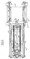
- FIGURE 15 is an enlarged fragmentary view showing details of the clamping table 42 and clamping cylinder 46.
- clamping cylinder 46 is of telescoping construction, including an extendable hollow cylinder rod 164 which telescopes over fixed inner cylinder rod 166 which, in turn, is secured to mainframe base 14 by nut 168.
- Outer cylinder sleeve 169 in turn, telescopes over rod 164 so that the potential stroke of cylinder 46 is almost twice the stroke of a conventional cylinder.
- the telescoping construction of cylinder 46 permits a more compact assembly, without the need for a pit beneath the floor to accommodate the required stroke of a conventional cylinder.
- a suitable telescoping cylinder for this purpose is manufactured by Precision Hydraulics & Engineering, Inc., of Signal Hill, California.
- the vertical position of lower ejector pin actuators 48 is sensed by upper and lower limit switches 170, 172, respectively, which are tripped by flanges on lower ejector pin actuators 48.
- Ejector pin actuators hang or are spring-biased to their downward position illustrated in FIGURES 15 and 16, but they are adapted to be displaced upwardly when cylinders 50 are extended.
- bottom stool 26 is provided with a conventional ejector plate mechanism (not illustrated) adapted to be engaged and actuated by ejector pin actuators 48 so that ejector pins 390 (see FIGURE 53) may enter aligned holes in drag 28 to eject the completed core from the drag cavity.
- FIGURE 15 shows a mainframe crossmember 174 on which cope hangers 76 are mounted for pivotal movement under the influence of hydraulic cylinders 176. Cylinders 176 cause hangers 76 to swing from a stand-by position, which provides clearance for vertical passage of tooling 24, and an extended position in which they support the upper core box ore cope. A pair of limit switches 178 sense the two pivotal positions to cope hanger 76.
- FIGURE 16 illustrates additional details of the clamping table and related structure.
- Guidance and stabilization of clamping table 42 throughout its vertical movement is provided by guide rod bushings 180 which are secured to frame crossmember 182. These bushings receive guide rods 184 which are secured to the underside of clamping table 42.
- Also shown in FIGURE 16 are two of the four clamping units 186 which are pivotally secured to brackets 188 and caused to pivot by shafts 190. As will be further explained below, clamping units 186 function to clamp tooling 24 to clamping table 42.
- FIGURES 17 and 18 there is illustrated the mechanism for causing pivotal rails 40 to swing out of the path of the tooling.
- the rails are mounted for pivotal movement with pivot shafts 192.
- Hydraulic rotary actuators 44 cause rotational movement of shafts 192 by means of a rack and pinion arrangement which is not illustrated but which may be similar to that illustrated in FIGURE 41.
- Brackets 194 are similarly clamped to pivot shafts 192 so that actuation causes simultaneous pivotal movement of brackets 194, shaft 192 and rails 40.
- Contact screws 196 are mounted on brackets 194 for engagement with rail position-indicating limit switches 198 and 200.
- FIGURES 19-22 show the clamping mechanism for clamping tooling 24 to table 42.
- cylinders 202 have shaft extensions 190 which simultaneously stroke outwardly upon actuation of the cylinder.
- Each shaft has a camming slot 204 which is skewed relative to the shaft axis, as seen in FIGURE 21.
- Follower pin 206 in clamp 186 rides in slot 204, whereby longitudinal stroking of shaft 190 by cylinder 202 causes the sides of slot 204 to cam follower pin 206 so as to pivot clamp 186 into or out of its clamping position.
- clamp 186 engages a flange on bottom stool 26 to retain tooling 24 in position on table 42.
- Shaft extensions 190 carry actuators 208 which trip limit switches 210 to indicate the condition of clamps 186.
- FIGURE 23 is a sectional view of the previously described structure beneath clamping table 42, showing table clamp cylinder 46, guide rods 184, lower ejector pin actuators 48 and a representative lower limit switch 172.
- FIGURE 24 illustrates the mechanism for sensing the vertical elevation of clamping table 42.
- a pair of vertical rods 214 extend downwardly from the underside of the table, each rod having an enlarged cam portion 216 adapted to trip limit switches 218 to thereby indicate when the table has reached a predetermined position.
- FIGURES 25-28 illustrate, in further detail, the cope hanger construction previously described in relation to FIGURE 15.
- Cope 30 is shown in phantom in the plan view of FIGURE 25 and in the fragmentary cross-sectional elevation of FIGURE 27.
- Each of cope hangers 76 is mounted for pivotal movement with a pivot shaft 220 which is rotatably received within bracket 222 secured to frame crossmember 174.
- Cylinder rod 224 of cope hanger actuating cylinder 176 is connected to an actuating lever 226 which is secured to pivot shaft 220 for rotation therewith.
- linear movement of cylinder rod 224 causes pivotal movement of lever 226, shaft 220 and cope hanger 76.
- Brackets 228 provide support for the opposite end of each of hydraulic cylinders 176.
- each of cope hangers 76 has an upwardly tapering cope locating pin 230 which is adapted to seat in a downwardly opening socket 232 at each of the four corners of cope 30. In this manner, cope hangers 76 function to both locate and support cope 30 during the appropriate portion of the cycle.
- a limit switch actuator 234 on each of cylinder rods 224 functions to trip the appropriate limit switch 178 to indicate the condition and position of cope hangers 76.
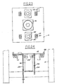
- FIGURES 29 and 30 show further details of the gassing manifold and ejector plate transfer mechanism generally shown in FIGURE 1.
- a gassing manifold transfer support frame 66 is secured to one end of mainframe 10.
- Hydraulic cylinder 68 which functions to traverse gassing manifold transfer carriage 70 between its active and stand-by positions, has a cylinder rod 236 which is secured to a bracket 238 on carriage 70.
- carriage 70 is shown in its operative position at the left side of the figure, whereas the stand-by position is shown in phantom at the right side of the figure.
- Carriage 70 is supported during its traverse by means of guide rods 240, which are mounted on mainframe 10 and gassing manifold transfer support frame 66, and by guide rod bushings 242 on carriage 70 (see FIGURE 31 for further illustration of the guide rods and bushings).
- a pair of shock absorbers 244 is mounted on frame 66 to cushion the end of the stroke of gassing manifold transfer carriage 70 as it reaches the end of its stroke toward its stand-by position.
- another pair of shock absorbers 246 is mounted on carriage 70 itself (see FIGURES 29 and 35). When the carriage reaches the end of its stroke toward its operative position, the spring-loaded plungers of shock absorbers 246 engage stop members 248 which are carried by brackets 250 mounted on mainframe member 252.
- limit switches provide a signal when carriage 70 has reached its respective positions. Specifically, an actuator 254 on carriage 70 trips limit switch 256 on support frame 66 when the carriage reaches its stand-by position, whereas limit switch 258 on mainframe member 252 is positioned to be tripped by actuator 260 on carriage 70 when the carriage reaches its operative position.
- FIGURES 30 and 31 further show two pairs of gassing manifold hanger brackets 72, 73 which are mounted on carriage 70 and which engage retainer brackets 74 on gassing manifold and ejector plate 32, as will be further described below.
- FIGURES 32 and 33 illustrate the actuating mechanism for the upper ejector pins.
- a pair of hydraulic cylinders 262 is secured to a portion of mainframe 10.
- Output rods 264 of the cylinders extend downwardly into selective engagement with the first of the series of interengaging rocker arms 266, each of which is pivotally mounted on a bracket 268 secured to top plate 270 of gassing manifold and ejector plate 32.
- a plurality of parting line pins are secured to the underside of ejector pin plate 274 and extend downwardly into engagement with the top of drag 28 when the mold boxes are closed and in raised position against gassing manifold bottom plate 278. These parting line pins prevent downward deflection of ejector pin plate 274 until the mold boxes have separated from each other, thereby preventing damaging premature pressure of ejector pins 280 on the newly-formed core within the mold cavity.
- the access openings for pushrods 272 are provided with guide bushings and suitable sealing means to substantially prevent gas leakage therethrough.
- FIGURE 32 also illustrates one of a pair of gas pipe connections 282 which supply catalyzing gas to the interior of gassing manifold 32, as will be further discussed below.
- FIGURE 34 shows an enlarged detail of gassing manifold hanger bracket 72.
- Bracket 72 has a cut-out portion 284 which is adapted to receive a portion retainer bracket 74 on gassing manifold and ejector plate 32.
- hydraulic cylinder 286 is actuated to extend cylinder rod 288 to clamp gassing manifold retainer bracket 74 within hanger bracket 72.
- cylinder rod 288 permits separation of gassing manifold and ejector plate 32 from hanger bracket 72.
- FIGURE 35 shows the manner in which upper ejector pin hydraulic cylinder 262 is secured to mainframe member 252.
- FIGURES 36 and 37 in addition to showing the previously described hydraulic cylinder 262 which actuates the upper ejector pins, further show the connections for supplying catalyzing gas to gassing manifold and ejector plate 32.
- gas pipe connection 282 is fixed to top plate 270 of the gassing manifold and ejector plate 32.
- the upper opening of connection 282 is moved upwardly into abutting and sealed connection with a fixed gas supply pipe 290 which is secured to mainframe crossmember 252.
- an O-ring 286 is provided to seal this abutting connection.
- the upper end of supply pipe 290 is connected to a source of catalyzing gas (unillustrated).
- gas is caused to flow through pipe 290 and connection 282 into gassing manifold chamber 281 (see FIGURE 33) and from such chamber through the clearance gaps surrounding ejector pins 280 in bottom plate 278 and into aligned channels in cope 30 leading to the formed part within the mold box cavity.
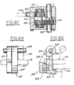
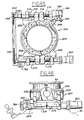
- FIGURE 38 shows additional details of sand magazine 36 and the clamping mechanism by which blow plate 34 is clamped to the lower side of the sand magazine. Additional details of the clamping mechanism are shown in FIGURES 41-44, which should be referred to in connection with the following description.
- the blow plate clamping mechanism includes a pair of clamping cylinders 294 which are secured to main frame 10 by means of bracket 296. Each of cylinders 294 has a cylinder rod 298 which abuts the end of a cooperating rack gear 300. Both rack gears engage a pinion gear 302 which rotates in conjunction with adjacent pinion gear 304 on the same shaft. Gear 304 in turn meshes with spur gear 306 which is keyed to shaft 308.
- Rack gears 300, pinion gears 302 and 304, spur gear 306 and shaft 308 are all mounted within gear housing 310 secured to sand magazine 36. At each end of shaft 308 there is a bevel gear set 312 which provides driving engagement with similar bevel gears on three additional clamping shafts 314.
- shaft 308 and the three additional shafts 314 are arrayed around four sides of sand magazine 36 and are rotatably mounted in brackets 316 secured to the sand magazine.
- FIGURES 43 and 44 illustrate the manner in which a typical clamping unit 318 clamps blow plate 34 to sand magazine 36.
- Each clamping unit comprises a clamping arm 320 and an actuating arm 322, each keyed to shaft 308.
- a lateral projection 324 on arm 322 overlaps arm 320, and a compression spring 326 retained between these overlapping portions continuously biases the arms away from each other.
- actuating arm 322 is keyed to shaft 308 for direct pivotal movement therewith, it can be seen in FIGURE 43 that key 328 for clamping arm 320 is placed in an oversized slot 330 in arm 320. This arrangement permits a limited amount of lost motion between the rotation of shaft 310 and the pivoting movement of clamping arm 320.
- FIGURES 38 and 41 also illustrate a limit switch arrangement which signals the condition of the blow plate clamping system.
- Each of hydraulic cylinders 294 has a cylinder rod extension 332 provided with a pair of limit switch actuators 334 which engage one or the other of a pair of limit switches 336.
- these limit switches generate a signal which indicates whether the clamping mechanism is in either its clamped or released condition.
- FIGURES 38 and 40 also illustrate a pair of guide brackets 338 secured to the corners of sand magazine 36. These brackets are provided with guide holes 340 through which cylinder rods 264 of the upper ejector pin actuating mechanism project (see also FIGURES 35-36).
- FIGURE 39 also shows a handle and locking device 342 for a sand magazine clean-out door. Also shown is a pneumatic line 344 fixed to mainframe 10 and adapted to connect with connector line 346 on sand magazine 36 at coupling joint 348 when brought into abutting engagement upon upward movement of the sand magazine. This pressurized air is used to actuate exhaust vent valves 58 between their open position during sand charging and their closed position during blowing.
- FIGURES 45 and 46 illustrate blow body clamping assembly 350 which forms a part of blow sleeve 54 and which removably clamps blow sleeve 352 to sand magazine flange 354.
- Assembly 350 includes annular blow body 356 from which extend four brackets 358 which in turn support reversible hydraulic drive motor 360 and rotatably mounted threaded drive shaft 362.
- Rotation of drive shaft 362 causes simultaneous rotation of driven shaft 364 by means of sprockets 366, 368 and connecting drive chain 370.
- Shafts 362 and 364 are each provided with oppositely threaded segments so that shaft rotation causes the two opposed C-clamp rings 376, 378 to move toward or away from each other, depending upon the direction of rotation.
- Actuator 380 on C-clamp ring 376 is positioned to trip limit switches 382, 384 to thereby generate signals responsive to the clamped or released condition of clamping assembly 350.
- Air inlet 386 provides a connection point for blowing air from supply tank 62 and blow control valve 64 (see FIGURE 2).
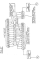
- FIGURE 47 is a simplified schematic block diagram showing a control system for operating the foundry machine of the present invention. It is contemplated that the operating cycle would be controlled by a suitable programmable controller, such as manufactured by Allen-Bradley of Milwaukee, Wisconsin.
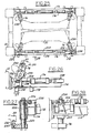
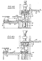
- FIGURE 1 shows all of the tooling 24 initially on tool loading table 18.
- the tooling includes sand magazine 36, blow plate 34, gassing manifold and ejector plate 32, cope 30, drag 28 and bottom stool 26. These elements are merely stacked on each other by appropriate nesting or other formations. They are not clamped together.
- the arms of core pick-off unit 100 are in their illustrated retracted position.
- Pivotable rails 40 on mainframe 10 are in their normal vertically oriented operative position, as illustrated in FIGURE 17.
- Transfer cylinder 90 is then actuated to bring gripper jaws 96 of carriage 82 into engagement with tooling coupling 98 on bottom stool 26.
- hydraulic cylinder 118 is actuated to clamp jaws 96 onto coupling 98, and the tooling may then be transferred from tool loading and pick-off table 18 onto the aligned pivotable rails 40 of mainframe 10 (see FIGURES 4-6 and 10-14). That is the condition of the apparatus shown in solid lines in FIGURE 48.
- gripper jaws 96 are released from tooling coupling 98 so that trolley 78 and carriage 82 may be returned to their stand-by position illustrated in phantom in FIGURE 48.
- Table clamp cylinder 46 is then actuated to lift tooling 24 off of pivotable rails 40 and to bring tooling 24 up into engagement with blow sleeve 54.
- rotary actuator 44 is actuated to swing rails 40 outwardly to provide clearance for the table to be subsequently lowered below its starting position (see FIGURES 15-18).
- hydraulic cylinders 202 are actuated to clamp bottom stool 26 to the table by means of clamping units 186 (see FIGURES 19-22).
- cope hangers 76 are in their withdrawn position (shown in phantom in FIGURE 25), to provide clearance for the vertically moving tooling.
- Sand magazine 36 is the clamped to blow sleeve 54 by clamping assembly 350 (see FIGURES 45-46), and blow plate 34 is clamped to sand magazine 36 by clamping units 318 (see FIGURES 38-44).
- gassing manifold transfer carriage 70 is brought from its stand-by position shown in FIGURE 48 to its clamping position shown in FIGURE 49 by means of hydraulic cylinder 68.
- Hydraulic cylinder 286 is actuated to clamp hanger bracket 72 to retainer bracket 74 on gassing manifold 32 (see FIGURES 29 to 34).
- cope hangers 76 are swung into their operative position by means of hydraulic cylinders 176 (see FIGURES 25-28).
- clamping table 42 is lowered to permit carriage 70 to move gassing manifold and top ejector plate 32 to its stand-by position.
- upper core box or cope 30 is deposited onto cope hangers 76 so that it is supported thereby.
- Bottom stool 26 and lower core box or drag 28 continue to move downwardly with clamping table 42, thus establishing the separation from cope 30 as shown in FIGURE 50.
- sand and binder are introduced into hopper 52 and a butterfly valve (not illustrated) is opened by valve actuator 56 to admit this charge into sand magazine 36 (see FIGURE 2).
- the butterfly valve is then closed and the sand magazine is pressurized with air from tank 62. This pressurization forces the sand from the magazine through blow plate 34 and into the core-defining cavity within the core boxes, thereby forming the core.
- table 42 is lowered a sufficient distance to permit carriage 70 to transfer gassing manifold and ejector plate 32 into position beneath blow plate 34.
- Table 42 is once again raised to engage the underside of the gassing manifold and ejector plate. This upward movement brings gas pipe connection 282 on the gassing manifold into sealing contact with fixed gas supply pipe 284 (see FIGURES 36-37). This is the condition illustrated in FIGURE 52.
- Catalyzing gas is then introduced through these connections into the gassing manifold and ejector plate 32 and into the core boxes, catalyzing and hardening the newly-formed core. Purging air is then applied to the mold box cavity through the same path as the gas to remove excess gas.
- cope hangers 76 are swung back into their operative position.
- Table 42 is lowered, and simultaneously top ejector pins 280 are actuated by hydraulic cylinder 262 (see FIGURE 33) and lower ejector cylinders 50 are actuated.
- cope 30 engages cope hangers 76 and becomes supported thereby while table 42 and drag 28 continue down.
- the top ejector plate is no longer constrained by the parting line pins and can move downwardly under the pressure from cylinder 262.
- Top ejector pins force core 388 out of the cope cavity.
- lower ejector pin actuators 48 descend into contact with the upwardly extended rods of lower ejector cylinders 50, camming actuators 48 up into engagement with the lower ejector pin mechanism within bottom stool 26, thereby extending lower ejector pins 390 therefrom, and ejecting core 388 from drag 28.
- the fingers of pick-off unit 100 are then swung to their active position by rotary actuator 102 (see FIGURE 6).
- FIGURE 53 core 388 is shown supported on lower ejector pins 390, with sufficient gap above drag 28 to permit the fingers of pick-off unit 100 to enter.
- Carriage transfer cylinder 90 is actuated to cause carriage 82 and trolley 78 to traverse toward the right as viewed in FIGURE 53 so that the pick-off fingers 100 are properly positioned beneath core 388.
- Lower ejector cylinders 50 are then retracted so that core 388 is gently placed onto and supported by the pick-off unit fingers.
- Trolley 78 is then retracted toward its stand-by position shown in FIGURE 53, from which the core can be removed either manually or by robotic equipment.
- FIGURE 53 shows gassing manifold and ejector plate 32 in its retracted position.
- the withdrawal of that unit by carriage 70 can occur as soon as part 388 has been ejected from the molds. However, it may be preferable to defer such withdrawal until after part 388 has been removed by fingers 100, because gas vapors which may be harmful to the blow fan may be still be given off by part 388 after its ejection.
- the gassing manifold and ejector plate 32 if temporarily left in place on cope 30, can shield such vulnerable parts from these vapors.
- table 46 is then raised to carry stool 26, drag 28 and cope 30 up into engagement with blow plate 34, whereupon the cycle can be repeated.
- gassing manifold and ejector plate 32 is returned to its position beneath blow plate 34 (if it was not previously left in such position), and work table 42 is raised to carry stool 26, drag 28, cope 30 and gassing manifold and ejector plate 32 up into engagement with blow plate 34, with empty carriage 70 first being withdrawn to its stand-by position when cope 30 is raised far enough to engage and support gassing manifold and ejector plate 32.
- Clamps 318 and 350 are then released to disengage sand magazine 36 from blow plate 34 and from blow body 54. While work table 42 is in its raised position, pivotable rails 40 are swung back into their operative position. Table 42, with all of the tooling 24 stacked thereon, may then be lowered to bring wheels 38 of stool 26 to rest on tracks 40, whereupon carriage 82 is actuated toward the right by cylinder 90 so that gripper jaws 96 can engage tooling coupling 98 on tooling 24. Then, carriage 82 is returned to its stand-by position, bringing the tooling 24 onto tool-loading and pick-off table 18.
Landscapes
- Engineering & Computer Science (AREA)
- Mechanical Engineering (AREA)
- Casting Devices For Molds (AREA)
Claims (6)
― auf dem Grundrahmen (10) angeordnete Formwerkzeug-Aufnahmemittel (40, 76) zur Aufnahme wenigstens von Teilen der Formwerkzeuge (24) während bestimmter Abschnitte des Maschinenarbeitszyklus;
― wobei die Formwerkzeug-Aufnahmemittel Formkasten-Trenneinrichtungen (76) zum Trennen der beiden Formkästen (28, 30) voneinander nach Bildung des Teils in den Formkasten-Ausnehmungen umfaßt, wobei ferner die Auswerf-Einrichtungen (50, 390) in der Weise arbeiten, daß sie ein fertiggestelltes Teil (388) aus den getrennten Formkästen (28, 30) auswerfen und das ausgeworfene Teil (388) im Abstand zu den Formkästen (28, 30) halten;
― ferner einen stationären Formwerkzeug-Ladetisch (18) neben dem Grundrahmen (10) und dem Arbeitstisch (42);
― beweglich auf dem Formwerkzeug-Ladetisch (18) angeordnete Formwerkzeug-Transfereinrichtungen (82) zum Überführen der Formwerkzeuge (24) zu und von den Formwerkzeug-Aufnahmemitteln;
― Teile-Entnahmeeinrichtungen (78, 100) zum Entnehmen eines fertiggestellten Teils (388) von den Auswerfeinrichtungen (390), wobei die Teile-Entnahmeeinrichtungen (78, 100) für ein maschinelles Bewegen des Formwerkzeug-Ladetisches (18) zwischen einer Stand-by-Position und einer Arbeitsposition ausgerüstet sind, in der dieser ein ausgeworfenes, fertiggestelltes Teil (388) erfaßt, dieses Teil von den Auswerfeinrichtungen (390) entnimmt, während die Formwerkzeuge (24) weiterhin vom Grundrahmen gehalten werden, und dann das Teil (388) vom Grundrahmen (10) abführt; und
― an dem Formwerkzeug-Ladetisch (18) angeordnete Antriebsmittel (90) zur Erzeugung und Steuerung einer maschinellen Verfahrbewegung der Formwerkzeug-Transfereinrichtungen (82) sowie der Teile-Entnahmeeinrichtungen (78, 100).
Applications Claiming Priority (2)
| Application Number | Priority Date | Filing Date | Title |
|---|---|---|---|
| US07/034,173 US4757855A (en) | 1987-04-02 | 1987-04-02 | Method and apparatus for loading and unloading tooling from a foundry machine |
| US34173 | 1987-04-02 |
Publications (2)
| Publication Number | Publication Date |
|---|---|
| EP0284841A1 EP0284841A1 (de) | 1988-10-05 |
| EP0284841B1 true EP0284841B1 (de) | 1991-07-24 |
Family
ID=21874760
Family Applications (1)
| Application Number | Title | Priority Date | Filing Date |
|---|---|---|---|
| EP88103618A Expired EP0284841B1 (de) | 1987-04-02 | 1988-03-08 | Verfahren und Vorrichtung zum Beladen und Entladen einer Werkzeugausrüstung in einer Giessereimaschine |
Country Status (3)
| Country | Link |
|---|---|
| US (1) | US4757855A (de) |
| EP (1) | EP0284841B1 (de) |
| DE (2) | DE3863809D1 (de) |
Families Citing this family (11)
| Publication number | Priority date | Publication date | Assignee | Title |
|---|---|---|---|---|
| JP2977094B2 (ja) * | 1993-12-03 | 1999-11-10 | アドルフ・ホッティンガー・マシーンバウ・ゲーエムベーハー | 鋳造用シェルすなわち鋳造用シェル組立体の製造装置及び製造方法 |
| WO1998019810A1 (de) * | 1996-11-04 | 1998-05-14 | Hottinger Maschinenbau Gmbh | Vorrichtung und verfahren zur herstellung giessfertiger masken oder kernpakete |
| AU2000272708A1 (en) * | 2000-09-19 | 2002-04-02 | Georg Fischer Disa A/S | Mould-making machine with means for moving an upper core box to an inspection, cleaning, etc. position |
| CN103506584B (zh) * | 2013-10-08 | 2015-04-01 | 衢州市依科达节能技术有限公司 | 垂直分型无箱射压造型机防夹器 |
| CN103537631B (zh) * | 2013-11-09 | 2015-04-01 | 衢州乐创节能科技有限公司 | 一种铸造件内模装配机 |
| CN103537633B (zh) * | 2013-11-15 | 2015-04-01 | 衢州乐创节能科技有限公司 | 一种轨道型内模装配机 |
| CN103600037B (zh) * | 2013-11-30 | 2015-07-29 | 衢州市依科达节能技术有限公司 | 一种摇臂型装配机 |
| CN103639373B (zh) * | 2013-12-22 | 2015-04-29 | 衢州市依科达节能技术有限公司 | 一种升降型摇臂装配机 |
| CN103896076B (zh) * | 2014-03-21 | 2015-11-18 | 仪征亚新科双环活塞环有限公司 | 造型自动化生产线的拆盘机构 |
| CN106672336A (zh) * | 2016-12-30 | 2017-05-17 | 嘉善中建钢结构安装有限公司 | 一种封箱机 |
| CN114406206B (zh) * | 2022-02-10 | 2023-07-21 | 苏州明志科技股份有限公司 | 紧凑型射芯机 |
Family Cites Families (7)
| Publication number | Priority date | Publication date | Assignee | Title |
|---|---|---|---|---|
| US3107402A (en) * | 1961-06-02 | 1963-10-22 | Pettibone Mulliken Corp | Core-unloading apparatus for an automatic core-making machine |
| US3096547A (en) * | 1961-09-14 | 1963-07-09 | Pettibone Mulliken Corp | Automatic core-making machine |
| US3528481A (en) * | 1968-10-17 | 1970-09-15 | Pettibone Corp | Core making machine with hardening gas manifold |
| US3625078A (en) * | 1969-11-21 | 1971-12-07 | Acme Cleveland Corp | Elevating table |
| US4100961A (en) * | 1976-11-18 | 1978-07-18 | Acme-Cleveland Corporation | Foundry molding machine |
| SU864660A1 (ru) * | 1980-07-15 | 1987-08-15 | Центральное Проектно-Конструкторское И Технологическое Бюро "Главсантехпрома" | Механизм выдачи стержней |
| DE3405420A1 (de) * | 1983-11-08 | 1985-05-15 | Rheinische Maschinenfabrik & Eisengiesserei Anton Röper GmbH & Co KG, 4060 Viersen | Vorrichtung zum wechseln von werkzeugen in giessereimaschinen |
-
1987
- 1987-04-02 US US07/034,173 patent/US4757855A/en not_active Expired - Fee Related
-
1988
- 1988-03-08 DE DE8888103618T patent/DE3863809D1/de not_active Expired - Fee Related
- 1988-03-08 EP EP88103618A patent/EP0284841B1/de not_active Expired
- 1988-03-08 DE DE198888103618T patent/DE284841T1/de active Pending
Also Published As
| Publication number | Publication date |
|---|---|
| EP0284841A1 (de) | 1988-10-05 |
| JPS642761A (en) | 1989-01-06 |
| US4757855A (en) | 1988-07-19 |
| DE3863809D1 (de) | 1991-08-29 |
| DE284841T1 (de) | 1989-02-16 |
Similar Documents
| Publication | Publication Date | Title |
|---|---|---|
| EP0284841B1 (de) | Verfahren und Vorrichtung zum Beladen und Entladen einer Werkzeugausrüstung in einer Giessereimaschine | |
| US8235698B2 (en) | Blowing machine and automatic changer | |
| EP2195130B1 (de) | Für eine spritzgiessvorrichtung verwendete kerneinstellvorrichtung und verfahren zum einstellen eines kerns | |
| KR20180074640A (ko) | 로봇 핸들러를 구비한 성형 머신 | |
| US4832108A (en) | Method and apparatus for handling tooling within a foundry machine | |
| CN113829575B (zh) | 橡胶自动化生产线及控制方法 | |
| US3397259A (en) | Method for casting articles | |
| EP0284842B1 (de) | Verfahren und Vorrichtung zur Handhabung einer Werkzeugausrüstung in einer Giessereimaschine | |
| US4840218A (en) | Automatic matchplate molding system | |
| US4890664A (en) | Automatic matchplate molding system | |
| US5394599A (en) | Method for automatically exchanging a stamper unit with another one | |
| EP0040987B1 (de) | Maschine und Verfahren zur Herstellung hohler Gegenstände, z.B. Giesserei-Hohlkerne | |
| EP0494762B1 (de) | Vorrichtung zur Herstellung von Kernen | |
| EP0443287B1 (de) | Horizontal geteilte Formmaschine vom Typ stationärer Kernunterkasten | |
| CN1326644C (zh) | 对铸型进行造型的装置 | |
| JP2000317943A (ja) | タイヤ加硫機及びタイヤ加硫設備 | |
| US3303536A (en) | Process and apparatus for automatically producing and assembling foundry molds | |
| JPH012762A (ja) | 型込機械におけるガス抜きマニホルド | |
| US2791012A (en) | Core box top handling mechanism | |
| US3328852A (en) | Foundry sand forming machines | |
| US4378835A (en) | Foundry core or mold making machine | |
| US4714100A (en) | Method and apparatus for changing a mold box on a molding machine | |
| US4044818A (en) | Apparatus for forming sand molds | |
| US4718474A (en) | Mold transfer mechanism for a molding machine | |
| US5701946A (en) | Apparatus for shooting foundry cores or molds |
Legal Events
| Date | Code | Title | Description |
|---|---|---|---|
| PUAI | Public reference made under article 153(3) epc to a published international application that has entered the european phase |
Free format text: ORIGINAL CODE: 0009012 |
|
| AK | Designated contracting states |
Kind code of ref document: A1 Designated state(s): AT BE CH DE ES FR GB GR IT LI LU NL SE |
|
| RBV | Designated contracting states (corrected) |
Designated state(s): DE FR GB IT |
|
| ITCL | It: translation for ep claims filed |
Representative=s name: MODIANO & ASSOCIATI S.R.L. |
|
| 17P | Request for examination filed |
Effective date: 19881107 |
|
| EL | Fr: translation of claims filed | ||
| DET | De: translation of patent claims | ||
| 17Q | First examination report despatched |
Effective date: 19900208 |
|
| RAP1 | Party data changed (applicant data changed or rights of an application transferred) |
Owner name: ROBERTS SINTO CORPORATION (A MICHIGAN CORPORATION) |
|
| GRAA | (expected) grant |
Free format text: ORIGINAL CODE: 0009210 |
|
| AK | Designated contracting states |
Kind code of ref document: B1 Designated state(s): DE FR GB IT |
|
| REF | Corresponds to: |
Ref document number: 3863809 Country of ref document: DE Date of ref document: 19910829 |
|
| ITF | It: translation for a ep patent filed | ||
| ET | Fr: translation filed | ||
| PGFP | Annual fee paid to national office [announced via postgrant information from national office to epo] |
Ref country code: FR Payment date: 19911227 Year of fee payment: 5 |
|
| PGFP | Annual fee paid to national office [announced via postgrant information from national office to epo] |
Ref country code: GB Payment date: 19920213 Year of fee payment: 5 |
|
| PGFP | Annual fee paid to national office [announced via postgrant information from national office to epo] |
Ref country code: DE Payment date: 19920330 Year of fee payment: 5 |
|
| PLBE | No opposition filed within time limit |
Free format text: ORIGINAL CODE: 0009261 |
|
| STAA | Information on the status of an ep patent application or granted ep patent |
Free format text: STATUS: NO OPPOSITION FILED WITHIN TIME LIMIT |
|
| 26N | No opposition filed | ||
| PG25 | Lapsed in a contracting state [announced via postgrant information from national office to epo] |
Ref country code: GB Effective date: 19930308 |
|
| GBPC | Gb: european patent ceased through non-payment of renewal fee |
Effective date: 19930308 |
|
| PG25 | Lapsed in a contracting state [announced via postgrant information from national office to epo] |
Ref country code: FR Effective date: 19931130 |
|
| PG25 | Lapsed in a contracting state [announced via postgrant information from national office to epo] |
Ref country code: DE Effective date: 19931201 |
|
| REG | Reference to a national code |
Ref country code: FR Ref legal event code: ST |
|
| PG25 | Lapsed in a contracting state [announced via postgrant information from national office to epo] |
Ref country code: IT Free format text: LAPSE BECAUSE OF NON-PAYMENT OF DUE FEES;WARNING: LAPSES OF ITALIAN PATENTS WITH EFFECTIVE DATE BEFORE 2007 MAY HAVE OCCURRED AT ANY TIME BEFORE 2007. THE CORRECT EFFECTIVE DATE MAY BE DIFFERENT FROM THE ONE RECORDED. Effective date: 20050308 |