EP0283538A1 - Dispositif détecteur - Google Patents
Dispositif détecteur Download PDFInfo
- Publication number
- EP0283538A1 EP0283538A1 EP87104470A EP87104470A EP0283538A1 EP 0283538 A1 EP0283538 A1 EP 0283538A1 EP 87104470 A EP87104470 A EP 87104470A EP 87104470 A EP87104470 A EP 87104470A EP 0283538 A1 EP0283538 A1 EP 0283538A1
- Authority
- EP
- European Patent Office
- Prior art keywords
- detector
- stage
- light guides
- circuit
- individual optics
- Prior art date
- Legal status (The legal status is an assumption and is not a legal conclusion. Google has not performed a legal analysis and makes no representation as to the accuracy of the status listed.)
- Granted
Links
- 230000005855 radiation Effects 0.000 claims abstract description 39
- 238000005259 measurement Methods 0.000 claims abstract description 16
- 239000007787 solid Substances 0.000 claims abstract description 15
- 238000001514 detection method Methods 0.000 claims abstract description 9
- 230000001419 dependent effect Effects 0.000 claims abstract description 3
- 230000010355 oscillation Effects 0.000 claims description 14
- 230000003287 optical effect Effects 0.000 claims description 6
- 238000011156 evaluation Methods 0.000 claims description 4
- 230000001960 triggered effect Effects 0.000 claims 1
- 230000035945 sensitivity Effects 0.000 description 8
- 230000000875 corresponding effect Effects 0.000 description 5
- 238000003384 imaging method Methods 0.000 description 4
- 230000005484 gravity Effects 0.000 description 3
- 239000013307 optical fiber Substances 0.000 description 3
- 239000003990 capacitor Substances 0.000 description 2
- 230000002596 correlated effect Effects 0.000 description 2
- 230000003111 delayed effect Effects 0.000 description 2
- 238000000034 method Methods 0.000 description 2
- 238000012545 processing Methods 0.000 description 2
- 230000003595 spectral effect Effects 0.000 description 2
- 230000002123 temporal effect Effects 0.000 description 2
- 229910052691 Erbium Inorganic materials 0.000 description 1
- 206010016754 Flashback Diseases 0.000 description 1
- 229910052689 Holmium Inorganic materials 0.000 description 1
- 238000001069 Raman spectroscopy Methods 0.000 description 1
- 230000003321 amplification Effects 0.000 description 1
- 230000002238 attenuated effect Effects 0.000 description 1
- 230000000903 blocking effect Effects 0.000 description 1
- 238000006243 chemical reaction Methods 0.000 description 1
- 230000001276 controlling effect Effects 0.000 description 1
- 238000013461 design Methods 0.000 description 1
- KRHYYFGTRYWZRS-DYCDLGHISA-N deuterium fluoride Chemical compound [2H]F KRHYYFGTRYWZRS-DYCDLGHISA-N 0.000 description 1
- 230000000694 effects Effects 0.000 description 1
- UYAHIZSMUZPPFV-UHFFFAOYSA-N erbium Chemical compound [Er] UYAHIZSMUZPPFV-UHFFFAOYSA-N 0.000 description 1
- KJZYNXUDTRRSPN-UHFFFAOYSA-N holmium atom Chemical compound [Ho] KJZYNXUDTRRSPN-UHFFFAOYSA-N 0.000 description 1
- 238000003199 nucleic acid amplification method Methods 0.000 description 1
- 239000010979 ruby Substances 0.000 description 1
- 229910001750 ruby Inorganic materials 0.000 description 1
Images

Classifications
-
- G—PHYSICS
- G01—MEASURING; TESTING
- G01S—RADIO DIRECTION-FINDING; RADIO NAVIGATION; DETERMINING DISTANCE OR VELOCITY BY USE OF RADIO WAVES; LOCATING OR PRESENCE-DETECTING BY USE OF THE REFLECTION OR RERADIATION OF RADIO WAVES; ANALOGOUS ARRANGEMENTS USING OTHER WAVES
- G01S7/00—Details of systems according to groups G01S13/00, G01S15/00, G01S17/00
- G01S7/48—Details of systems according to groups G01S13/00, G01S15/00, G01S17/00 of systems according to group G01S17/00
- G01S7/4804—Auxiliary means for detecting or identifying lidar signals or the like, e.g. laser illuminators
-
- G—PHYSICS
- G01—MEASURING; TESTING
- G01S—RADIO DIRECTION-FINDING; RADIO NAVIGATION; DETERMINING DISTANCE OR VELOCITY BY USE OF RADIO WAVES; LOCATING OR PRESENCE-DETECTING BY USE OF THE REFLECTION OR RERADIATION OF RADIO WAVES; ANALOGOUS ARRANGEMENTS USING OTHER WAVES
- G01S3/00—Direction-finders for determining the direction from which infrasonic, sonic, ultrasonic, or electromagnetic waves, or particle emission, not having a directional significance, are being received
- G01S3/78—Direction-finders for determining the direction from which infrasonic, sonic, ultrasonic, or electromagnetic waves, or particle emission, not having a directional significance, are being received using electromagnetic waves other than radio waves
- G01S3/7803—Means for monitoring or calibrating
-
- G—PHYSICS
- G01—MEASURING; TESTING
- G01S—RADIO DIRECTION-FINDING; RADIO NAVIGATION; DETERMINING DISTANCE OR VELOCITY BY USE OF RADIO WAVES; LOCATING OR PRESENCE-DETECTING BY USE OF THE REFLECTION OR RERADIATION OF RADIO WAVES; ANALOGOUS ARRANGEMENTS USING OTHER WAVES
- G01S3/00—Direction-finders for determining the direction from which infrasonic, sonic, ultrasonic, or electromagnetic waves, or particle emission, not having a directional significance, are being received
- G01S3/78—Direction-finders for determining the direction from which infrasonic, sonic, ultrasonic, or electromagnetic waves, or particle emission, not having a directional significance, are being received using electromagnetic waves other than radio waves
- G01S3/781—Details
-
- G—PHYSICS
- G01—MEASURING; TESTING
- G01S—RADIO DIRECTION-FINDING; RADIO NAVIGATION; DETERMINING DISTANCE OR VELOCITY BY USE OF RADIO WAVES; LOCATING OR PRESENCE-DETECTING BY USE OF THE REFLECTION OR RERADIATION OF RADIO WAVES; ANALOGOUS ARRANGEMENTS USING OTHER WAVES
- G01S3/00—Direction-finders for determining the direction from which infrasonic, sonic, ultrasonic, or electromagnetic waves, or particle emission, not having a directional significance, are being received
- G01S3/78—Direction-finders for determining the direction from which infrasonic, sonic, ultrasonic, or electromagnetic waves, or particle emission, not having a directional significance, are being received using electromagnetic waves other than radio waves
- G01S3/782—Systems for determining direction or deviation from predetermined direction
- G01S3/783—Systems for determining direction or deviation from predetermined direction using amplitude comparison of signals derived from static detectors or detector systems
- G01S3/784—Systems for determining direction or deviation from predetermined direction using amplitude comparison of signals derived from static detectors or detector systems using a mosaic of detectors
-
- G—PHYSICS
- G01—MEASURING; TESTING
- G01S—RADIO DIRECTION-FINDING; RADIO NAVIGATION; DETERMINING DISTANCE OR VELOCITY BY USE OF RADIO WAVES; LOCATING OR PRESENCE-DETECTING BY USE OF THE REFLECTION OR RERADIATION OF RADIO WAVES; ANALOGOUS ARRANGEMENTS USING OTHER WAVES
- G01S7/00—Details of systems according to groups G01S13/00, G01S15/00, G01S17/00
- G01S7/48—Details of systems according to groups G01S13/00, G01S15/00, G01S17/00 of systems according to group G01S17/00
- G01S7/483—Details of pulse systems
- G01S7/486—Receivers
- G01S7/4861—Circuits for detection, sampling, integration or read-out
-
- G—PHYSICS
- G01—MEASURING; TESTING
- G01S—RADIO DIRECTION-FINDING; RADIO NAVIGATION; DETERMINING DISTANCE OR VELOCITY BY USE OF RADIO WAVES; LOCATING OR PRESENCE-DETECTING BY USE OF THE REFLECTION OR RERADIATION OF RADIO WAVES; ANALOGOUS ARRANGEMENTS USING OTHER WAVES
- G01S7/00—Details of systems according to groups G01S13/00, G01S15/00, G01S17/00
- G01S7/48—Details of systems according to groups G01S13/00, G01S15/00, G01S17/00 of systems according to group G01S17/00
- G01S7/483—Details of pulse systems
- G01S7/486—Receivers
- G01S7/4865—Time delay measurement, e.g. time-of-flight measurement, time of arrival measurement or determining the exact position of a peak
Definitions
- the invention relates to a detector device for the direction-dependent detection of laser radiation with at least a first and second, each having an opto-electrical converter detector stage, with a plurality of individual optics, which collectively determine a predetermined total solid angle, the solid angles of adjacent individual optics overlapping one another and the individual optics are each arranged in azimuth planes, with a first and second light guide for each individual optical system, the light guides leading to the first and second detector stages, all of the first light guides having the same length and leading to the first detector stage, while the second leads to the second detector stage Light guides are of different lengths from one another and their lengths are graduated in the azimuth angular direction to form different transit times and with a transit time measuring device which is connected to the first and second detector stages by A Determine the beginning and end of the transit time measurement and, depending on this, the azimuth angle of the incident laser radiation.
- the azimuth plane is understood to mean a horizontal plane in which the azimuth angles are measured.
- Laser radiation which radiates in the visible or infrared range, is used in many and varied ways in the military field. Most often, pulsed or intensity-modulated laser radiation is used to determine the distance for fire control systems, to illuminate a target for the target identification of a missile sensor and for direct control of the missile in connection with laser beacons.
- the type of threat must be determined beforehand. It is therefore necessary to determine the laser radiation yourself at the target and to identify it from a disturbing background radiation. It is also necessary to determine the characteristic features of this laser radiation, e.g. to analyze their wavelength and the signature with regard to the pulse length and the pulse repetition rate.
- targeted countermeasures which can either be passive as a change of location to deceive wrong targets and fogging or active in the form of flashbacks or direct combat, it is particularly necessary to measure the direction of incidence of the laser radiation precisely to the target.
- the width of the detected solid angle and for the angular resolution of a warning sensor in the azimuth direction and elevation direction For different types of targets, such as vehicles, ships, helicopters, airplanes and satellites, there are different requirements for the width of the detected solid angle and for the angular resolution of a warning sensor in the azimuth direction and elevation direction.
- a threat from angle areas close to the horizontal plane e.g. from other tanks or low-lying helicopters
- the detection range is therefore an angular range of 360 ° in the azimuth plane and an angular range of ⁇ 30 ° in the elevation plane.
- the elevation plane is understood to mean any plane perpendicular to the azimuth plane in which the elevation angles are measured.
- the movements of vehicles around the vertical axis are much slower. This means that the azimuth measurement remains valid for a much longer period of time.
- additional means e.g.
- the laser radiation source can be precisely located by means of visionary observation of the landscape structure. So that the detection of the laser radiation source is possible in every movement position of the vehicle, the full sensitivity of the radiation sensor must be guaranteed over the entire required elevation range. This means that the radiation sensor must cover the entire azimuth elevation area without gaps.
- the required and desired solid angle range is usually 360 ° in the azimuth direction and ⁇ 90 ° in the elevation direction.
- the user In addition to the different requirements for the angle detection of laser warning sensors, the user also wishes to be able to determine as different laser radiation sources as possible with one and the same device.
- the radiation detectors In view of the large number of different military laser radiation sources in the range from short-wave visible light to radiation in the thermal infrared region, the radiation detectors must not be restricted in terms of spectral sensitivity and readiness for reception by filters which are arranged in front of the photodetectors, these filters themselves serve to reduce interference from the backlight. Such filters automatically reduce the spectral sensitivity of such opto-electrical sensors.
- the wavelength ranges for frequency-shifted excimer lasers are 0.4 ⁇ m to 0.5 ⁇ m, for ruby lasers 0.69 ⁇ m, for laser diodes 0.85 ⁇ m to 0.95 ⁇ m, for alexandrite lasers 0.75 ⁇ m to 0.85 ⁇ m, for Nd: YAG 1.06 ⁇ m and 1.32 ⁇ m, for Nd: YAG-methane Raman Shifted 1. 52 ⁇ m, for erbium 1.65 ⁇ m, for holmium 2.12 ⁇ m, for deuterium Fluoride 3.6 ⁇ m to 4.0 ⁇ m, for CO2 lasers 9.5 ⁇ m to 11.5 ⁇ m.
- the laser radiation sensor must work properly and functionally under the most varied lighting conditions. It must also be ensured that the false alarm rate remains low when the sun is shining directly into the field of view of the radiation sensor.
- Such a laser radiation sensor must also be insensitive to other artificial lighting sources in which no laser radiation is emitted, e.g. Stroboscopes, flashlights, cannon fire, light bombs, flashes, etc.
- a large dynamic signal range must also be detected by the detector device, in order to ensure that the detector device is in itself even in different weather conditions, with different distances between the warning sensor and the radiation source when the pulse energy of the laser changes changing impact of the laser radiation at the target and in the event of turbulence fluctuations in the atmosphere across the beam cross-section works perfectly.
- disturbances in the angle measurement caused by secondary reflections of the laser radiation in the surroundings and at the target must be avoided as far as possible.
- the detector device mentioned at the outset is known from DE-PS 33 23 828 and from DE-OS 35 25 5l8.
- the direction of the incident laser radiation is therefore determined and determined with the aid of a transit time measurement, the laser radiation being guided in optical fibers.
- two light guides are provided behind a common individual optics. Depending on the size of the solid angle to be detected, numerous such individual optics are provided. Adjacent individual optics have overlapping individual solid angle ranges. All the first light guides of the individual optics are led to a first detector, which starts a transit time measurement circuit when a laser pulse or laser pulse arrives. All of the second light guides, each of different lengths, are connected to a second detector, by means of which the counting circuit started is stopped.
- the counting circuit is stopped sooner or later.
- These light guides serve as delay lines for the laser radiation.
- the time difference between the start and the stop of the counter circuit is a measure of the angle in the azimuth plane. Since several of the light guide pairs are provided in connection with the individual optics for controlling the time measurement circuit and adjacent individual optics overlap in terms of their solid angle, an all-round view and complete solid angle detection is ensured. Since all of the first light guides are of the same length, the respective start pulse occurs at the same time after the arrival of a laser pulse.
- the invention is based on the object of providing a detector device of the type mentioned at the outset which in a simple manner enables an exact angle determination on the basis of the transit time measurement, without the need for a time-consuming and complex shifting of the center of gravity.
- the influence of interference signals should be kept as low as possible.
- the opto-electrical handler of the first and second detector stages is connected to a damped resonant circuit, and that the duration of the rise phase of a resonance oscillation until the amplitude is reached is greater than or equal to the typical duration or rise time of a laser pulse arriving at least on a single optical unit and that the damped resonant circuit of the first and second detector stages in each case a zero-crossing detector stage is arranged in order to generate a start or stop signal for the transit time measuring circuit at the first zero crossing or one of the following zero crossings of the damped vibrations in question.
- Another advantage of the invention can be seen in the fact that the mode of operation of the detector device is independent of the pulse amplitude, since the linear range of the opto-electrical converter (photodiode) is used. There are no falsifications of the phase due to possible non-linear amplifications of the signals. A very wide dynamic signal range of e.g. > 120 dB can be recorded.
- the damped resonant circuit with a defined resonance frequency acts like a selective filter with a defined bandwidth. Signals in the range of the resonance frequency are passed on with low attenuation, while frequency components of the signals that lie outside the bandwidth are attenuated very strongly.
- laser pulses with a width between 10 ns to 200 ns are used, or long pulses with pulse lengths in the range from microseconds to seconds.
- long pulses generally have very short rise times in the range from 50 ns to 200 ns.
- laser pulses Compared to other fast light processes with rise times greater than a few microseconds, laser pulses have oscillation frequency components of a noticeably higher frequency. This means that with a selective vibration filter that is tuned to a fixed or average fundamental frequency of the laser pulse, this fundamental frequency including the adjacent frequency components within the bandwidth can be effectively separated from other light processes.
- laser pulse components with a width of T bring about a resonance effect on the damped resonant circuit when its resonance frequency is inversely proportional to the eight times the value of the laser pulse width. Based on the width of the laser pulses mentioned above, an optimal oscillation frequency in the range of a few MHz results.
- a false signal circuit which has a time window stage which can be influenced by the first and second detector stages and which generates a blocking signal for the transit time measuring circuit or a downstream evaluation circuit if the time between the start signal and the stop signal is greater than the maximum transit time difference between the longest second light guide and the first light guide.
- This has the advantage that a time measurement is only initiated and evaluated if the start signal and the stop signal in the time window 1.
- the damped resonant circuit of the first and second detector stages is followed by a threshold value stage with a variable trigger threshold, which can be changed by an interference signal detector circuit in which the frequency of the interference signal peaks, for. B.
- the probability of detection of signals on the opto-electrical converter for weak laser pulses depends on the level of the set trigger threshold, there is the advantage that e.g. with weak daylight, the sensitivity of the device is much higher than with strong sunlight, namely in the visible and in the infrared sensitivity range of the opto-electrical converter.
- the two zero crossing detector stages or threshold value stages are advantageously connected to a digital logic circuit.
- the transit time measuring circuit is expediently a counting circuit clocked by an oscillator.
- each of the individual optics is additionally assigned a third light guide
- the third light guides of individual optics located in the same elevation plane perpendicular to the azimu plane are of different lengths from one another and are stepped in the elevation angle direction and lead to a third detector stage, which is also connected to a damped resonant circuit.
- all third light guides in the azimuth plane each have the same length. This means that regardless of the azimuth angular position of the incident laser radiation, the sensitivity seen in the elevation direction is the same.
- all second light guides of an elevation level are each of the same length. This means that the sensitivity in the azimuth angle direction is independent of the determined elevation direction of the laser radiation.
- a detector stage for generating a stop signal is assigned to each of the two rows of light beams.
- a common detector stage is provided for measuring the transit time difference in both elevation and azimuth directions to create the start signal.
- the sensor head of a detector device is designated by 1.
- This sensor head is a spherical housing which has a large number of openings in the azimuth direction and in the elevation direction.
- individual optics which are designated as 2 in FIG. 1 for all optics.
- the individual optics form groups for the subsequent evaluation in the respective azimuth levels and in the elevation levels.
- There are three light guides behind the individual optics. The end of the respective light guide is arranged in the focal plane or imaging plane of each individual optic 2.
- the first light guide of the first individual optics of the top azimuth plane is designated L111, while the first light guide offset by l80 ° of this plane is designated L 11n .
- the first light guide of the first single optics of the underlying azimuth plane is labeled L121 etc.
- the first light guide of the first single optics of the lowest azimuth plane is labeled L 1n1
- the light guide offset by 180 ° is labeled L 1nn .
- All these first light guides L111 to L 1nn have the same length and are guided in a bundle to an optical system 3, which is used to image the end face on a detector device 4.
- This detector device or stage 4 is also referred to as the start stage.
- the second light guide of the first individual optics of the top azimuth plane is designated L 211 , while the light guide offset by 180 ° is designated L 21n .
- the second light guide of the first individual optics of the lowest azimuth plane is designated L 2n1 , while the light guide offset by 180 ° bears the designation L 2nn .
- the second light guide L211 to L 2n1 located in a common elevation plane are brought together as a light guide bundle and guided to a second receiving optics 5, which images the front ends of these light guides on a second detector stage.
- These second light guides L211 to L 2n1 of the first elevation level have the same length. As can be seen from FIG. 1, these first individual optics are perpendicular to the azimuth planes.
- the individual second light guides of the individual optics which are offset by 180.degree. From the previously mentioned first individual optics , lie in a common elevation plane and which are denoted by L 21n to L 2nn are guided as a bundle to the same receiving optics 5. They are of equal length to one another. However, these light guides are longer than the previously mentioned light guides of the first individual optics. The same applies to the individual second light guides of those individual optics which are each in a common elevation plane and which has an intermediate azimuth angle with respect to the first individual optics.
- the designated 6 Detector stage is also referred to as the first stop stage.
- the graded differences in length between the light guides of neighboring elevation levels are the same size. This means that the measured difference in length with respect to the first light guide is a measure of the azimuth angle at which an incoming laser pulse strikes the spherical head of the detector device.
- the third light guide of the first single optics of the top azimuth level is designated L311, while the third light guide offset by l80 ° of the same level is designated L 31n .
- All light guides L311 to L 31n are brought together as a bundle and led to a receiving optics 7, which images the end of the bundle end on a detector stage 8, which is also referred to as the second stop stage.
- the aforementioned light guides L311 to L 31n have the same length.
- the third light guide of the first individual optics of the lowest azimuth plane is designated L 3n1 .
- the light guide of the same plane, offset by 180 °, has the reference symbol L 3nn .
- These light guides L 3n1 to L 3nn are combined as a bundle and lead to the aforementioned receiving or imaging optics 7, so that their front ends are also imaged on the third detector stage 8 (second stop stage).
- These light guides L 3n1 to L 3nn are mutually the same length. However, the length of this light guide bundle is different from the length of the light guide of the top azimuth plane. It is also conceivable that the length gradation of the individual light guides of the different azimuth planes takes place in a different way.
- the equatorial plane of the spherical head is considered the original azimuth plane and that the corresponding third light guides of this plane have a first length, while the lengths of the light guide groups of the azimuth planes above and below are each symmetrical have the same length.
- the gradation is chosen accordingly.
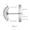
- Fig. 2 shows a cross section through the ball sensor head l partially cut.
- the parts corresponding to the parts in FIG. 1 are provided with the same reference numerals.
- the first light guides L111 to L 1nn are guided to the imaging optics 3 in order to image the front ends of these light guides on a photodiode 9 of the first detector stage 4.
- the photodiode 9 is connected in series with a damped resonant circuit which consists of a coil l0, a capacitor ll and a resistor l2.
- This parallel resonant circuit is also connected to an amplifier 13 at whose output a current flow I occurs.
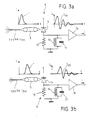
- a laser pulse L is transmitted via the light guide bundle L 11 and L 1nn , which has a current profile shown in FIG. 3. It is assumed that the width of this laser pulse is 50 ns.
- the damped oscillation curve of the current of the damped oscillation circuit is also shown in FIG. 3a. In a subsequent stage, which is not shown in FIG. 3a, the first zero crossing I40 of the damped oscillation is determined and used as the start signal for a counting circuit shown in FIG. 4.
- Fig. 3b the second light guide bundle L211 to L 2nn is shown, which is guided to the imaging optics 5 of the detector stage (first stop stage) 6.
- the photodiode of this detector stage is labeled 14.
- the photodiode l4 is connected to a damped resonant circuit which consists of a resistor l5, a coil l6 and a capacitor l7.
- This resonant circuit has a resonant frequency which is equal to the resonant frequency of the resonant circuit shown in FIG. 3a. This means that the two resonant circuits are identical.
- a secondary amplifier is designated by l8. As can be seen from FIG.
- the laser pulse strikes the receiving optics 5 and consequently the photodiode 14.
- the damped vibration also starts with a corresponding delay.
- the first zero crossing of this damped oscillation is designated I60. This first zero crossing is delayed compared to the first zero crossing of the undelayed damped oscillation from FIG. 3a.
- the difference between the first zero crossings is the delay time, which is a measure of the azimuth angle of the incoming laser beam.
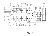
- the start channel is formed by the first light guide L111 to L 1nn in connection with the first detector stage 5, the resonant circuit l0, ll, l2 and the repeater l3 as well as a downstream threshold level 20 with a variable response level.
- the second channel or first stop channel is formed by the second light guide L211 to L 2nn , the second detector stage (first stop stage) with the photodiode l4, the resonant circuit l5, l6, l7, the repeater l8 and a downstream threshold level 2l with a variable response level.
- the outputs of the two threshold value stages 20 and 2l lead to an emitter-coupled logic circuit 22, in which an analog-digital conversion of the received signals is carried out. In addition, a zero point crossing determination is carried out in this circuit stage 22.
- This emitter-coupled logic circuit 22 is followed by a counter circuit 23, which is clocked by an oscillator 24.
- the counter circuit 23 is connected on the output side to a microcomputer 25 which has control outputs which lead to control inputs of the threshold value circuits 20 and 2l.
- the threshold value is automatically readjusted depending on the background lighting in order to avoid interference signals as far as possible.
Landscapes
- Physics & Mathematics (AREA)
- Engineering & Computer Science (AREA)
- General Physics & Mathematics (AREA)
- Radar, Positioning & Navigation (AREA)
- Remote Sensing (AREA)
- Electromagnetism (AREA)
- Computer Networks & Wireless Communication (AREA)
- Optics & Photonics (AREA)
- Optical Radar Systems And Details Thereof (AREA)
Priority Applications (4)
| Application Number | Priority Date | Filing Date | Title |
|---|---|---|---|
| DE8787104470T DE3764362D1 (de) | 1987-03-26 | 1987-03-26 | Detektorvorrichtung. |
| ES87104470T ES2016816B3 (es) | 1987-03-26 | 1987-03-26 | Dispositivo de deteccion |
| EP87104470A EP0283538B1 (fr) | 1987-03-26 | 1987-03-26 | Dispositif détecteur |
| US07/165,639 US4825063A (en) | 1987-03-26 | 1988-03-08 | Radiation position detection using time-indicative variable-length fiber array |
Applications Claiming Priority (1)
| Application Number | Priority Date | Filing Date | Title |
|---|---|---|---|
| EP87104470A EP0283538B1 (fr) | 1987-03-26 | 1987-03-26 | Dispositif détecteur |
Publications (2)
| Publication Number | Publication Date |
|---|---|
| EP0283538A1 true EP0283538A1 (fr) | 1988-09-28 |
| EP0283538B1 EP0283538B1 (fr) | 1990-08-16 |
Family
ID=8196870
Family Applications (1)
| Application Number | Title | Priority Date | Filing Date |
|---|---|---|---|
| EP87104470A Expired - Lifetime EP0283538B1 (fr) | 1987-03-26 | 1987-03-26 | Dispositif détecteur |
Country Status (4)
| Country | Link |
|---|---|
| US (1) | US4825063A (fr) |
| EP (1) | EP0283538B1 (fr) |
| DE (1) | DE3764362D1 (fr) |
| ES (1) | ES2016816B3 (fr) |
Cited By (5)
| Publication number | Priority date | Publication date | Assignee | Title |
|---|---|---|---|---|
| DE3818229C1 (fr) * | 1988-05-28 | 1989-12-07 | Messerschmitt-Boelkow-Blohm Gmbh, 8012 Ottobrunn, De | |
| WO1998022833A1 (fr) * | 1996-11-19 | 1998-05-28 | Tracor Aerospace, Inc. | Systeme de guidage par fibres optiques pour missiles guides par laser |
| WO2008141800A1 (fr) * | 2007-05-22 | 2008-11-27 | Eads Deutschland Gmbh | Dispositif et procédé de détection et de localisation de sources de rayonnement laser |
| DE102012022258A1 (de) | 2012-11-14 | 2014-05-15 | Eads Deutschland Gmbh | Sensor zur Erkennung und Lokalisierung von Laserstrahlungsquellen |
| EP3663798A1 (fr) * | 2018-12-07 | 2020-06-10 | Sick Ag | Détecteur optoélectronique et procédé de détection et de détermination de distance des objets |
Families Citing this family (17)
| Publication number | Priority date | Publication date | Assignee | Title |
|---|---|---|---|---|
| DE3833634A1 (de) * | 1988-10-04 | 1990-04-12 | Messerschmitt Boelkow Blohm | Laserwarnsensor |
| US5085507A (en) * | 1989-12-27 | 1992-02-04 | Texas Instruments Incorporated | Device for three dimensional tracking of an object |
| US5030824A (en) * | 1990-02-22 | 1991-07-09 | The Boeing Company | Optical position sensor employing encoder delay |
| US5355222A (en) * | 1992-05-15 | 1994-10-11 | Precision Tracking Fm, Inc. | Optical receiver for area location system |
| US6225619B1 (en) * | 1993-03-01 | 2001-05-01 | Pinecone Imaging Corporation | Optical fiber-based imaging instrument |
| US5619332A (en) * | 1995-05-15 | 1997-04-08 | Tracor, Inc. | High spectral resolution fiber optic spectrometer |
| US6163372A (en) * | 1999-02-09 | 2000-12-19 | Marconi Aerospace Defense Systems Inc. | Fiber optic laser detection and ranging system |
| US6268822B1 (en) * | 1999-12-07 | 2001-07-31 | Alenia Marconi Systems Inc. | Dual-frequency millimeter wave and laser radiation receiver |
| DE10032162C1 (de) * | 2000-07-01 | 2001-10-11 | Lfk Gmbh | Verfahren und Vorrichtung zur Richtungserkennung von gepulsten Laserstrahlen nach dem Zeitintervallmeßprinzip |
| GB0024587D0 (en) | 2000-10-05 | 2001-08-15 | Matra Bae Dynamics Uk Ltd | Pulse shifted array |
| WO2002031451A2 (fr) * | 2000-10-10 | 2002-04-18 | The Johns Hopkins University | Dispositif et procede servant a detecter l'emplacement, l'intensite et le moment de declenchement d'une impulsion d'energie |
| US6507392B1 (en) | 2001-04-16 | 2003-01-14 | Bae Systems Information And Electronic Systems Integration Inc. | Single multiple aperture (“SMART”) lens system |
| US6943873B2 (en) * | 2001-07-17 | 2005-09-13 | Bae Systems Integrated Defense Solutions Inc. | Fiber optical laser detection and ranging system |
| GB0325785D0 (en) * | 2003-11-05 | 2004-08-04 | Mbda Uk Ltd | Detection of an electromagnetic signal |
| US20080127964A1 (en) * | 2006-11-27 | 2008-06-05 | Jiahua Han | Sun tracker |
| JP5918930B2 (ja) | 2011-04-11 | 2016-05-18 | 北日本電線株式会社 | アレイ型フォトモジュール |
| US10731977B1 (en) * | 2018-08-03 | 2020-08-04 | Rockwell Collins, Inc. | Automated zone accuracy for lever-arm and euler-angle alignment |
Citations (7)
| Publication number | Priority date | Publication date | Assignee | Title |
|---|---|---|---|---|
| US3428815A (en) * | 1965-10-22 | 1969-02-18 | Electronic Ind Eng Inc | Distance measuring system using infrared ring-around oscillator with a reference loop having a light conducting rod |
| US3601488A (en) * | 1968-09-27 | 1971-08-24 | Comp Generale Electricite | Apparatus for checking the proper operation of a laser telemeter |
| DE2634627A1 (de) * | 1976-07-31 | 1978-02-02 | Mitec Moderne Ind Gmbh | Laserentfernungsmessgeraet nach dem prinzip der laufzeitmessung |
| FR2372438A1 (fr) * | 1975-04-01 | 1978-06-23 | Elliott Brothers London Ltd | Dispositif de surveillance a detecteurs infrarouges |
| EP0057447A1 (fr) * | 1981-02-03 | 1982-08-11 | MTC Messtechnik und Optoelektronik AG | Appareil de mesure de distance selon le principe de la mesure de temps de propagation d'une impulsion de lumière |
| GB2112244A (en) * | 1981-12-18 | 1983-07-13 | Pilkington Perkin Elmer Ltd | Improvements in or relating to monitoring apparatus |
| DE3525518A1 (de) * | 1984-12-20 | 1986-07-10 | Messerschmitt-Bölkow-Blohm GmbH, 8012 Ottobrunn | Laserwarnsensor mit richtungserkennung |
Family Cites Families (3)
| Publication number | Priority date | Publication date | Assignee | Title |
|---|---|---|---|---|
| DE2360781A1 (de) * | 1973-03-02 | 1975-10-30 | Britz Hans Ernst | Elektronische auswertung fuer optoelektronische antennenanlage fuer laser-strahlen und strahlen mit aehnlichen ausbreitungsbedingungen |
| US4380391A (en) * | 1980-09-30 | 1983-04-19 | The United States Of America As Represented By The Secretary Of The Army | Short pulse CO2 laser for ranging and target identification |
| DE3323828C2 (de) * | 1983-07-01 | 1986-01-16 | Messerschmitt-Bölkow-Blohm GmbH, 8012 Ottobrunn | Laserwarnsensor |
-
1987
- 1987-03-26 DE DE8787104470T patent/DE3764362D1/de not_active Expired - Fee Related
- 1987-03-26 ES ES87104470T patent/ES2016816B3/es not_active Expired - Lifetime
- 1987-03-26 EP EP87104470A patent/EP0283538B1/fr not_active Expired - Lifetime
-
1988
- 1988-03-08 US US07/165,639 patent/US4825063A/en not_active Expired - Lifetime
Patent Citations (7)
| Publication number | Priority date | Publication date | Assignee | Title |
|---|---|---|---|---|
| US3428815A (en) * | 1965-10-22 | 1969-02-18 | Electronic Ind Eng Inc | Distance measuring system using infrared ring-around oscillator with a reference loop having a light conducting rod |
| US3601488A (en) * | 1968-09-27 | 1971-08-24 | Comp Generale Electricite | Apparatus for checking the proper operation of a laser telemeter |
| FR2372438A1 (fr) * | 1975-04-01 | 1978-06-23 | Elliott Brothers London Ltd | Dispositif de surveillance a detecteurs infrarouges |
| DE2634627A1 (de) * | 1976-07-31 | 1978-02-02 | Mitec Moderne Ind Gmbh | Laserentfernungsmessgeraet nach dem prinzip der laufzeitmessung |
| EP0057447A1 (fr) * | 1981-02-03 | 1982-08-11 | MTC Messtechnik und Optoelektronik AG | Appareil de mesure de distance selon le principe de la mesure de temps de propagation d'une impulsion de lumière |
| GB2112244A (en) * | 1981-12-18 | 1983-07-13 | Pilkington Perkin Elmer Ltd | Improvements in or relating to monitoring apparatus |
| DE3525518A1 (de) * | 1984-12-20 | 1986-07-10 | Messerschmitt-Bölkow-Blohm GmbH, 8012 Ottobrunn | Laserwarnsensor mit richtungserkennung |
Cited By (8)
| Publication number | Priority date | Publication date | Assignee | Title |
|---|---|---|---|---|
| DE3818229C1 (fr) * | 1988-05-28 | 1989-12-07 | Messerschmitt-Boelkow-Blohm Gmbh, 8012 Ottobrunn, De | |
| WO1998022833A1 (fr) * | 1996-11-19 | 1998-05-28 | Tracor Aerospace, Inc. | Systeme de guidage par fibres optiques pour missiles guides par laser |
| WO2008141800A1 (fr) * | 2007-05-22 | 2008-11-27 | Eads Deutschland Gmbh | Dispositif et procédé de détection et de localisation de sources de rayonnement laser |
| DE102007024051A1 (de) | 2007-05-22 | 2008-11-27 | Eads Deutschland Gmbh | Vorrichtung und Verfahren zur Erkennung und Lokalisierung von Laserstrahlungsquellen |
| DE102007024051B4 (de) * | 2007-05-22 | 2018-02-01 | Airbus Defence and Space GmbH | Vorrichtung und Verfahren zur Erkennung und Lokalisierung von Laserstrahlungsquellen |
| DE102012022258A1 (de) | 2012-11-14 | 2014-05-15 | Eads Deutschland Gmbh | Sensor zur Erkennung und Lokalisierung von Laserstrahlungsquellen |
| WO2014075652A1 (fr) | 2012-11-14 | 2014-05-22 | Eads Deutschland Gmbh | Capteur de détection et de localisation de sources de rayonnement laser |
| EP3663798A1 (fr) * | 2018-12-07 | 2020-06-10 | Sick Ag | Détecteur optoélectronique et procédé de détection et de détermination de distance des objets |
Also Published As
| Publication number | Publication date |
|---|---|
| ES2016816B3 (es) | 1990-12-01 |
| US4825063A (en) | 1989-04-25 |
| DE3764362D1 (de) | 1990-09-20 |
| EP0283538B1 (fr) | 1990-08-16 |
Similar Documents
| Publication | Publication Date | Title |
|---|---|---|
| EP0283538A1 (fr) | Dispositif détecteur | |
| DE19721105C2 (de) | Opto-eletronischer Sensor | |
| EP0066889B1 (fr) | Dispositif de commande de la dynamique pour un appareil de mesure de distance | |
| EP0143282B1 (fr) | Procédé pour la mesure sans contact de la température d'un objet par mesure du rayonnement sans influence du degré d'émissivité | |
| DE3530646A1 (de) | Flaechensicherung | |
| EP3347673B1 (fr) | Système détecteur optoélectronique sensible à la position et récepteur de rayon laser utilisant ce dernier | |
| DE2448651A1 (de) | Anordnung zum beruehrungslosen messen der abmessungen eines bewegten messobjekts | |
| EP1296161A2 (fr) | Barrière optique à séparateur de faisceaux | |
| EP0635731B1 (fr) | Méthode et capteur pour déterminer la limite de visibilité dans le brouillard épais | |
| DE69210455T2 (de) | Laserwarngerät und Modul zur Verwendung in einem derartigen Laserwarngerät | |
| DE3937859C1 (de) | Optischer Abstandszünder | |
| DE3020996A1 (de) | Einrichtung zur bestimmung der ausloeseentfernung von einem sich auf ein ziel zu bewegendem flugkoerper | |
| DE3219452C2 (de) | Dynamik-Steuerungsanordnung für ein Entfernungsmeßgerät | |
| DE102019112857A1 (de) | Koaxiales optisches System für LIDAR-Messungen (Light Detection and Ranging) | |
| DE3886928T2 (de) | Annäherungszünder. | |
| DE3401475C2 (fr) | ||
| EP3367050A1 (fr) | Cadre de mesure à filtre optique destiné à la détermination optique sans contact d'une position de trajet d'un projectile | |
| DE2923636A1 (de) | Messvorrichtung zur ermittlung der gegenseitigen kohaerenzfunktion eines laserstrahls | |
| DE102015007506B3 (de) | Vorrichtung und Verfahren zur Bestimmung einer Partikelgröße in einem Sprühstrahl | |
| DE2931818C2 (de) | Vorrichtung zur Erfassung der Einfallsrichtung elektromagnetischer, insbesondere optischer Strahlung | |
| DE2942355A1 (de) | Vorrichtung zum erfassen des durchganges eines projektils | |
| DE3231025C2 (de) | Einrichtung zur Identifizierung von gepulster Laserstrahlung | |
| DE2848625A1 (de) | Anordnung zum gebrauch in einem flugzeug zum detektieren von hindernissen | |
| DE3630401C1 (de) | Optischer Entfernungsmesser | |
| DE102004029343B4 (de) | Zielführungsvorrichtung für ein Fluggerät |
Legal Events
| Date | Code | Title | Description |
|---|---|---|---|
| PUAI | Public reference made under article 153(3) epc to a published international application that has entered the european phase |
Free format text: ORIGINAL CODE: 0009012 |
|
| 17P | Request for examination filed |
Effective date: 19880601 |
|
| AK | Designated contracting states |
Kind code of ref document: A1 Designated state(s): BE CH DE ES FR GB IT LI NL SE |
|
| 17Q | First examination report despatched |
Effective date: 19881110 |
|
| GRAA | (expected) grant |
Free format text: ORIGINAL CODE: 0009210 |
|
| AK | Designated contracting states |
Kind code of ref document: B1 Designated state(s): BE CH DE ES FR GB IT LI NL SE |
|
| ET | Fr: translation filed | ||
| GBT | Gb: translation of ep patent filed (gb section 77(6)(a)/1977) | ||
| REF | Corresponds to: |
Ref document number: 3764362 Country of ref document: DE Date of ref document: 19900920 |
|
| ITF | It: translation for a ep patent filed | ||
| ITTA | It: last paid annual fee | ||
| PLBE | No opposition filed within time limit |
Free format text: ORIGINAL CODE: 0009261 |
|
| STAA | Information on the status of an ep patent application or granted ep patent |
Free format text: STATUS: NO OPPOSITION FILED WITHIN TIME LIMIT |
|
| 26N | No opposition filed | ||
| EAL | Se: european patent in force in sweden |
Ref document number: 87104470.7 |
|
| REG | Reference to a national code |
Ref country code: GB Ref legal event code: 732E |
|
| REG | Reference to a national code |
Ref country code: CH Ref legal event code: PUE Owner name: DAIMLER-BENZ AEROSPACE AKTIENGESELLSCHAFT -DANN AN Ref country code: CH Ref legal event code: PFA Free format text: MESSERSCHMITT-BOELKOW-BLOHM GMBH TRANSFER- DEUTSCHE AEROSPACE AG * DEUTSCHE AEROSPACE AG TRANSFER- DAIMLER-BENZ AEROSPACE AKTIENGESELLSCHAFT |
|
| NLS | Nl: assignments of ep-patents |
Owner name: LFK LENKFLUGKOERPERSYSTEME GMBH;DEUTSCHE AEROSPACE |
|
| NLT1 | Nl: modifications of names registered in virtue of documents presented to the patent office pursuant to art. 16 a, paragraph 1 |
Owner name: DAIMLER-BENZ AEROSPACE AKTIENGESELLSCHAFT |
|
| REG | Reference to a national code |
Ref country code: ES Ref legal event code: PC2A |
|
| BECA | Be: change of holder's address |
Free format text: 19990210 *LFK-LENKFLUGKORPERSYSTEME G.M.B.H.:POSTFACH 80 11 49, 81663 MUENCHEN |
|
| BECH | Be: change of holder |
Free format text: 19990210 *LFK-LENKFLUGKORPERSYSTEME G.M.B.H.:POSTFACH 80 11 49, 81663 MUENCHEN |
|
| BECN | Be: change of holder's name |
Effective date: 19990210 |
|
| REG | Reference to a national code |
Ref country code: FR Ref legal event code: CJ Ref country code: FR Ref legal event code: CD |
|
| REG | Reference to a national code |
Ref country code: FR Ref legal event code: CD |
|
| REG | Reference to a national code |
Ref country code: FR Ref legal event code: TP |
|
| REG | Reference to a national code |
Ref country code: GB Ref legal event code: IF02 |
|
| PGFP | Annual fee paid to national office [announced via postgrant information from national office to epo] |
Ref country code: GB Payment date: 20020222 Year of fee payment: 16 |
|
| PGFP | Annual fee paid to national office [announced via postgrant information from national office to epo] |
Ref country code: CH Payment date: 20020225 Year of fee payment: 16 |
|
| PGFP | Annual fee paid to national office [announced via postgrant information from national office to epo] |
Ref country code: NL Payment date: 20020228 Year of fee payment: 16 |
|
| PGFP | Annual fee paid to national office [announced via postgrant information from national office to epo] |
Ref country code: SE Payment date: 20020305 Year of fee payment: 16 |
|
| PGFP | Annual fee paid to national office [announced via postgrant information from national office to epo] |
Ref country code: DE Payment date: 20020309 Year of fee payment: 16 |
|
| PGFP | Annual fee paid to national office [announced via postgrant information from national office to epo] |
Ref country code: FR Payment date: 20020315 Year of fee payment: 16 |
|
| PGFP | Annual fee paid to national office [announced via postgrant information from national office to epo] |
Ref country code: ES Payment date: 20020320 Year of fee payment: 16 |
|
| PGFP | Annual fee paid to national office [announced via postgrant information from national office to epo] |
Ref country code: BE Payment date: 20020322 Year of fee payment: 16 |
|
| PG25 | Lapsed in a contracting state [announced via postgrant information from national office to epo] |
Ref country code: GB Free format text: LAPSE BECAUSE OF NON-PAYMENT OF DUE FEES Effective date: 20030326 |
|
| PG25 | Lapsed in a contracting state [announced via postgrant information from national office to epo] |
Ref country code: SE Free format text: LAPSE BECAUSE OF NON-PAYMENT OF DUE FEES Effective date: 20030327 Ref country code: ES Free format text: LAPSE BECAUSE OF NON-PAYMENT OF DUE FEES Effective date: 20030327 |
|
| PG25 | Lapsed in a contracting state [announced via postgrant information from national office to epo] |
Ref country code: LI Free format text: LAPSE BECAUSE OF NON-PAYMENT OF DUE FEES Effective date: 20030331 Ref country code: CH Free format text: LAPSE BECAUSE OF NON-PAYMENT OF DUE FEES Effective date: 20030331 Ref country code: BE Free format text: LAPSE BECAUSE OF NON-PAYMENT OF DUE FEES Effective date: 20030331 |
|
| BERE | Be: lapsed |
Owner name: *LFK-LENKFLUGKORPERSYSTEME G.M.B.H. Effective date: 20030331 |
|
| PG25 | Lapsed in a contracting state [announced via postgrant information from national office to epo] |
Ref country code: NL Free format text: LAPSE BECAUSE OF NON-PAYMENT OF DUE FEES Effective date: 20031001 Ref country code: DE Free format text: LAPSE BECAUSE OF NON-PAYMENT OF DUE FEES Effective date: 20031001 |
|
| EUG | Se: european patent has lapsed | ||
| REG | Reference to a national code |
Ref country code: CH Ref legal event code: PL |
|
| GBPC | Gb: european patent ceased through non-payment of renewal fee |
Effective date: 20030326 |
|
| PG25 | Lapsed in a contracting state [announced via postgrant information from national office to epo] |
Ref country code: FR Free format text: LAPSE BECAUSE OF NON-PAYMENT OF DUE FEES Effective date: 20031127 |
|
| NLV4 | Nl: lapsed or anulled due to non-payment of the annual fee |
Effective date: 20031001 |
|
| REG | Reference to a national code |
Ref country code: FR Ref legal event code: ST |
|
| REG | Reference to a national code |
Ref country code: ES Ref legal event code: FD2A Effective date: 20030327 |
|
| PG25 | Lapsed in a contracting state [announced via postgrant information from national office to epo] |
Ref country code: IT Free format text: LAPSE BECAUSE OF NON-PAYMENT OF DUE FEES;WARNING: LAPSES OF ITALIAN PATENTS WITH EFFECTIVE DATE BEFORE 2007 MAY HAVE OCCURRED AT ANY TIME BEFORE 2007. THE CORRECT EFFECTIVE DATE MAY BE DIFFERENT FROM THE ONE RECORDED. Effective date: 20050326 |