EP0283342A1 - Rolling mill having axially shifting rolls, and roll profile control method - Google Patents
Rolling mill having axially shifting rolls, and roll profile control method Download PDFInfo
- Publication number
- EP0283342A1 EP0283342A1 EP88400372A EP88400372A EP0283342A1 EP 0283342 A1 EP0283342 A1 EP 0283342A1 EP 88400372 A EP88400372 A EP 88400372A EP 88400372 A EP88400372 A EP 88400372A EP 0283342 A1 EP0283342 A1 EP 0283342A1
- Authority
- EP
- European Patent Office
- Prior art keywords
- cylinders
- plane
- cylinder
- support
- bending
- Prior art date
- Legal status (The legal status is an assumption and is not a legal conclusion. Google has not performed a legal analysis and makes no representation as to the accuracy of the status listed.)
- Granted
Links
Images


Classifications
-
- B—PERFORMING OPERATIONS; TRANSPORTING
- B21—MECHANICAL METAL-WORKING WITHOUT ESSENTIALLY REMOVING MATERIAL; PUNCHING METAL
- B21B—ROLLING OF METAL
- B21B31/00—Rolling stand structures; Mounting, adjusting, or interchanging rolls, roll mountings, or stand frames
- B21B31/16—Adjusting or positioning rolls
- B21B31/18—Adjusting or positioning rolls by moving rolls axially
-
- B—PERFORMING OPERATIONS; TRANSPORTING
- B21—MECHANICAL METAL-WORKING WITHOUT ESSENTIALLY REMOVING MATERIAL; PUNCHING METAL
- B21B—ROLLING OF METAL
- B21B29/00—Counter-pressure devices acting on rolls to inhibit deflection of same under load, e.g. backing rolls ; Roll bending devices, e.g. hydraulic actuators acting on roll shaft ends
-
- B—PERFORMING OPERATIONS; TRANSPORTING
- B21—MECHANICAL METAL-WORKING WITHOUT ESSENTIALLY REMOVING MATERIAL; PUNCHING METAL
- B21B—ROLLING OF METAL
- B21B13/00—Metal-rolling stands, i.e. an assembly composed of a stand frame, rolls, and accessories
- B21B13/001—Convertible or tiltable stands, e.g. from duo to universal stands, from horizontal to vertical stands
-
- B—PERFORMING OPERATIONS; TRANSPORTING
- B21—MECHANICAL METAL-WORKING WITHOUT ESSENTIALLY REMOVING MATERIAL; PUNCHING METAL
- B21B—ROLLING OF METAL
- B21B31/00—Rolling stand structures; Mounting, adjusting, or interchanging rolls, roll mountings, or stand frames
- B21B31/16—Adjusting or positioning rolls
- B21B31/20—Adjusting or positioning rolls by moving rolls perpendicularly to roll axis
- B21B31/203—Balancing rolls
Landscapes
- Engineering & Computer Science (AREA)
- Mechanical Engineering (AREA)
- Control Of Metal Rolling (AREA)
- Metal Rolling (AREA)
- Reduction Rolling/Reduction Stand/Operation Of Reduction Machine (AREA)
- Soil Working Implements (AREA)
- Transplanting Machines (AREA)
- Bending Of Plates, Rods, And Pipes (AREA)
Abstract
Description
L'invention a pour objet un laminoir à cylindres déplaçables axialement et couvre également un procédé de réglage du profil et de répartition d'usure des cylindres dans un tel laminoir.The subject of the invention is a rolling mill with axially displaceable rollers and also covers a method of adjusting the profile and distributing wear of the rolls in such a rolling mill.
D'une façon générale , un laminoir comprend, à l'intérieur d'une cage de support ,au moins deux cylindres de travail s'appuyant, suivant un plan de serrage, sur au moins deux cylindres d'appui. Les cylindres sont portés à leurs deux extrémités par l'intermédiaire de roulements, dans des empoises montées mobiles, parallèlement au plan de serrage , dans des fenêtres ménagées sur chaque montant de la cage de support , chaque empoise étant munie de deux faces latérales de guidage coulissant le long de faces de glissement correspondantes ménagées sur le montant de la cage de part et d'autre de l'empoise.In general, a rolling mill comprises, inside a support cage, at least two working rolls resting, in a clamping plane, on at least two support rolls. The cylinders are carried at their two ends by means of bearings, in chocks mounted mobile, parallel to the clamping plane, in windows provided on each upright of the support cage, each chock being provided with two lateral guide faces. sliding along corresponding sliding faces formed on the amount of the cage on either side of the chock.
On utilise habituellement des laminoirs dits "quarto" comprenant deux cylindres de travail s'appuyant chacun sur un cylindre d'appui et des laminoirs dits "sexto" dans lesquels des cylindres intermédiaires sont interposés entre les cylindres d'appui et les cylindres de travail. Dans les deux cas, les axes des cylindres sont placés dans le plan de serrage , généralement vertical, mais on peut aussi appuyer chaque cylindre de travail sur un plus grand nombre de cylindres intermédiaires et/ou d'appui placés symétriquement de part et d'autre du plan de serrage.Usually called "quarto" rolling mills comprising two working rolls, each resting on a support cylinder and so-called "sexto" rolling mills in which intermediate rolls are interposed between the support rolls and the working rolls. In both cases, the axes of the cylinders are placed in the clamping plane, generally vertical, but it is also possible to support each working cylinder on a larger number of intermediate and / or support cylinders placed symmetrically on either side. other of the clamping plane.
Pour contrôler l'épaisseur du produit laminé et notamment obtenir une épaisseur égale dans le sens transversal à la direction de laminage, on réalise un cambrage ou cintrage des cylindres de travail et éventuellement des cylin dres intermédiaires au moyen de dispositifs de cambrage agissant sur les empoises du cylindre correspondant. Généralement , le dispositif de cambrage est constitué,pour chaque empoise, de deux ensembles de vérins placés symétriquement de part et d'autre de l'empoise. De plus, chaque partie d'appui de l'empoise s'appuie sur deux vérins écartés dans le sens axial symétriquement de part et d'autre du plan médian des roulements de l'empoise de façon que l'effort de cambrage soit bien réparti sur les roulements.To control the thickness of the rolled product and in particular to obtain a thickness equal in the direction transverse to the rolling direction, a bending or bending of the working rolls and possibly of the rolls is carried out. dres intermediaries by means of cambering devices acting on the chocks of the corresponding cylinder. Generally, the bending device consists, for each chock, of two sets of jacks placed symmetrically on either side of the chock. In addition, each support part of the chock rests on two cylinders spaced axially symmetrically on either side of the median plane of the chock bearings so that the bending force is well distributed on the bearings.
La cage du laminoir est symétrique par rapport à un plan médian perpendiculaire au plan de serrage et qui correspond au plan médian du produit laminé. Normalement les cylindres sont donc centrés sur ce plan par rapport auquel les empoises sont disposées symétriquement.The rolling mill stand is symmetrical with respect to a median plane perpendicular to the clamping plane and which corresponds to the median plane of the rolled product. Normally the cylinders are therefore centered on this plane with respect to which the chocks are arranged symmetrically.
Toutefois il peut être avantageux de réaliser un déplacement de certains cylindres parallèlement à leur axe et en sens contraire ou non , afin de satisfaire différents objectifs tels que la régularité de l'usure des cylindres ou le contrôle de la planéité ou du profil du produit laminé.However, it may be advantageous to carry out a displacement of certain cylinders parallel to their axis and in the opposite direction or not, in order to satisfy various objectives such as the regularity of the wear of the cylinders or the control of the flatness or of the profile of the rolled product. .
On conçoit que le déplacement axial des cylindres présente des difficultés lorsque ceux-ci sont soumis à un effort de cambrage. C'est pourquoi généralement, les deux opérations sont réalisées séparément, l'effort de cambrage étant supprimé lorsque l'on effectue un déplacement axial.It is understood that the axial displacement of the cylinders presents difficulties when the latter are subjected to a bending force. This is why generally, the two operations are carried out separately, the bending effort being eliminated when an axial movement is carried out.
Cependant, il est intéressant, pendant le laminage de combiner les effets de déplacement axial et du cambrage des cylindres et par conséquent, de pouvoir réaliser le déplacement axial des cy lindres tout en maintenant le cambrage. En outre le couple de rotation est généralement appliqué sur une seule paire de cylindres, et le cambrage des cylindres de travail, correspondants par frottement . Or il est nécessaire que tous les cylindres restent entraînés à la même vitesse périphérique .However, it is advantageous, during rolling, to combine the effects of axial displacement and the camber of the rolls and therefore to be able to effect the axial displacement of the cy lindres while maintaining the camber. In addition, the torque is generally applied to a single pair of cylinders, and the camber of the working cylinders, corresponding by friction. However, it is necessary that all the cylinders remain driven at the same peripheral speed.
D'ailleurs, le cambrage des cylindres de travail assure également un effet d'équilibrage entre les cylindres qu'il est utile de maintenir pendant le réglage axial même lorsque l'effort de laminage est supprimé.Moreover, the bending of the working rolls also ensures a balancing effect between the rolls which it is useful to maintain during the axial adjustment even when the rolling force is eliminated.
L'invention a pour objet un dispositif permettant d'effectuer un déplacement axial des cylindres sans cesser d'exercer l'effort de cambrage .The subject of the invention is a device allowing axial displacement of the cylinders without ceasing to exert the bending effort.
A cet effet, on a déjà proposé d'associer à chaque cylindre déplaçable et à ses empoises un cadre constitué de deux poutres montées coulissantes axialement sur la cage du laminoir et sur lesquelles prennent appui les dispositifs de cambrage qui, de la sorte, se déplacent en même temps que les cylindres, leurs empoises et le cadre . Cette disposition complique cependant la réalisation du laminoir.To this end, it has already been proposed to associate with each displaceable cylinder and its chocks a frame consisting of two beams mounted to slide axially on the stand of the rolling mill and on which the bending devices which thus move are supported. together with the cylinders, their chocks and the frame. This arrangement however complicates the production of the rolling mill.
L'invention a pour objet un nouveau dispositif permettant de réaliser en même temps le cambrage et le déplacement axial des cylindres de travail ou des cylindres intermédiaires sans modifier sensiblement la constitution du laminoir . L'invention permet notamment d'éviter les frottements élevés entre surfaces de guidage susceptibles de perturber les mouvements de réglage vertical des empoises.The invention relates to a new device making it possible to carry out at the same time the bending and the axial displacement of the working rolls or of the intermediate rolls without appreciably modifying the constitution of the rolling mill. The invention makes it possible in particular to avoid the high friction between guide surfaces liable to disturb the vertical adjustment movements of the chocks.
L'invention s'applique donc a un laminoir à cylindres déplaçables axialement comprenant, à l'intérieur d'une cage de support au moins deux cylindres de travail s'appuyant selon un plan de serrage P1, sur au moins deux cylindres d'appui et dont les extrémités sont portées, par l'intermédiaire de roulements dans des empoises montées coulissantes dans la cage de support, au moins l'un des cylindres de travail étant associé , d'une part à des moyens de déplacement dudit cylindre le long de son axe de part et d'autre d'une position de centrage des cylindres de travail sur le plan médian P2 de la cage , et d'autre part des moyens de cambrage dudit cylindre comprenant, pour chaque empoise deux ensembles symétriques d'au moins deux vérins de cambrage écartés l'un de l'autre dans le sens axial, et agissant respectivement sur des parties d'appui ménagées de chaque côté de l'empoise , lesdits ensembles de vérins étant placés à l'intérieur d'un bloc de support solidaire de la cage.The invention therefore applies to a rolling mill with axially displaceable rollers comprising, inside a support cage at least two working rolls resting on a clamping plane P1, on at least two support rolls and the ends of which are carried, by means of bearings in chocks slidably mounted in the support cage, at least one of the working cylinders being associated, on the one hand, with means for moving said cylinder along its axis on either side of a position for centering the working cylinders on the median plane P2 of the cage, and on the other hand means for bending said cylinder comprising, for each chock two symmetrical assemblies of at least two cambering cylinders spaced apart from one another in the axial direction, and acting respectively on support parts provided on each side of the chock, said sets of cylinders being placed inside a block of support secured to the cage.
Conformément à l'invention, chaque ensemble de vérins de cambrage prend appui dans le sens de l'effort de cambrage sur une pièce de glissement montée coulissante verticalement entre deux paires de faces de guidage ménagées dans un usinage réalisé à l'intérieur du bloc de support et respectivement parallèles et perpendiculaires au plan de laminage P1 et la partie d'appui correspondante de l'empoise prend appui avec possibilité de glissement sur une face plane et lisse ménagée sur ladite pièce de glissement du côté opposé au vérin de cambrage .According to the invention, each set of cambering cylinders is supported in the direction of the cambering force on a sliding part mounted to slide vertically between two pairs of guide faces formed in a machining carried out inside the block of support and respectively parallel and perpendicular to the rolling plane P1 and the corresponding support part of the chock rests with the possibility of sliding on a flat and smooth face formed on said sliding part on the side opposite to the camber cylinder.
De la sorte , on exerce l'effort de cambrage au moyen de vérins fixes prenant appui à chaque extrémité , d'un côté sur le bloc de support solidaire de la cage et de l'autre sur une pièce sur laquelle peut glisser l'empoise lors des déplacements axiaux , cette pièce étant montée coulissante sur le bloc de support dans le sens d'application de l'effort de cambrage et associée à des moyens d'encastrement permettant de résister aux effets de renversement dans le sens du déplacement axial des cylindres .In this way, the bending effort is exerted by means of fixed jacks bearing on each end, on one side on the support block secured to the cage and on the other on a part on which the chock can slide. during axial displacements, this part being slidably mounted on the support block in the direction of application of the bending force and associated with embedding means making it possible to resist the effects of overturning in the direction of the axial displacement of the cylinders .
Dans un mode de réalisation préférentiel , la pièce de glissement comprend des parties d'appui dans le sens de cambrage de chaque vérin de cambrage , s'étendant horizontalement au-dessus de chaque vérin et au moins une partie en forme de pied de guidage s'étendant verticalement en s'engageant entre deux faces écartées de guidage coulissant dudit pied, perpendiculaires au plan de laminage et ménagées sur deux faces opposées de l'usinage réalisé à l'intérieur du bloc de support 5.In a preferred embodiment, the sliding part comprises support parts in the cambering direction of each cambering cylinder, extending horizontally above each cylinder and at least one part in the form of a guide foot s extending vertically by engaging between two spaced apart sides of the sliding guide of said foot, perpendicular to the rolling plane and formed on two opposite faces of the machining carried out inside the support block 5.
Dans le cas le plus courant ou chaque ensemble de cambrage comprend deux vérins écartés l'un de l'autre et centrés dans un plan parallèle au plan de laminage , la pièce de glissement a la forme d'un T comportant une partie interne centrale formant le pied de guidage s'étendant verticalement entre les deux vérins à l'intérieur du bloc de support et une partie externe formant deux ailes s'étendant horizontalement de part et d'autre du pied de guidage , chacune au-dessus de l'un desdits vérins.In the most common case where each cambering assembly comprises two jacks spaced from each other and centered in a plane parallel to the rolling plane, the sliding part has the shape of a T having a central internal part forming the guide leg extending vertically between the two cylinders inside the support block and an outer part forming two wings extending horizontally on either side of the guide leg, each above one said jacks.
Le guidage ainsi réalisé permet de résister aux efforts de renversement résultant du désaxement des parties d'appui de l'empoise par rapport à la pièce de glissement lors des déplacements axiaux et , compte-tenu de la longueur du pied de guidage , ce dernier s'effectue avec des frottements faibles et ne pénalisant pas les mouvements verticaux .The guidance thus produced makes it possible to resist the overturning forces resulting from the offset of the support parts of the chock with respect to the sliding part during axial displacements and, taking into account the length of the guide foot, the latter s 'performs with low friction and does not penalize vertical movements.
Selon une autre caractéristique particulièrement avantageuse , la pièce de glissement est montée coulissante entre deux faces de guidage parallèles au plan de laminage et ménagées dans un second usinage réalisé à l'intérieur du bloc de support et prolongeant vers l'extérieur l'usinage interne dans lequel s'engage le pied de guidage .According to another particularly advantageous characteristic, the sliding part is slidably mounted between two guide faces parallel to the rolling plane and formed in a second machining carried out inside the support block and extending outward the internal machining in which engages the guide foot.
De préférence, ces deux faces de guidage parallèles au plan de laminage sont écartées symétriquement de part et d'autre du plan passant par les axes des vérins de cambrage et la partie d'appui de l'empoise est elle-même centrée dans le même plan dans lequel passent ainsi l'ensemble des efforts appliqués par le cambrage .Preferably, these two guide faces parallel to the rolling plane are symmetrically spaced apart on either side of the plane passing through the axes of the cambering cylinders and the support part of the chock is itself centered in the same plane in which thus pass all the forces applied by the bending.
De la sorte, dans le cas où chaque ensemble de cambrage comprend deux vérins écartés l'un de l'autre , l'usinage réalisé dans le bloc de support comprend une partie externe élargie passant au-dessus des deux vérins de cambrage dans laquelle est guidée la partie externe de la pièce de glissement 7 en forme de T sur laquelle s'appui d'un côté l'empoise et de l'autre les vérins de cambrage et une partie interne formant un puits central dans lequel est guidé le pied de guidage de la pièce de glissement .In this way, in the case where each cambering assembly comprises two cylinders spaced from one another, the machining carried out in the support block comprises an enlarged external part passing above the two cambering cylinders in which is guided the external part of the
Dans la plupart des cas, l'effet d'encastrement du pied de guidage permet de réaliser en même temps le déplacement axial et le cambrage des cylindres de travail en s'opposant au moment de renversement qui résulte du décalage du plan médian du roulement par rapport au plan de symétrie des deux paires de vérins de cambrage . Cependant , si ce décalage devient trop important, il se traduit par des frottements qui peuvent s'opposer au coulissement de la pièce de glissement .In most cases, the embedding effect of the guide foot makes it possible at the same time to carry out the axial displacement and the camber of the working rolls by opposing the moment of overturning which results from the offset of the median plane of the bearing by relation to the plane of symmetry of the two pairs of camber cylinders. However, if this offset becomes too large, it results in friction which can oppose the sliding of the sliding part.
Dans ce cas, selon une autre modalité de l'invention , il est intéressant d'appliquer des pressions différentes sur les deux vérins de chaque paire en tenant compte du décalage axial du cylindre de façon à annuler la somme des moments de renversement s'exercant sur la pièce de glissement et en réduisant ainsi au minimum les frottements de guidage de cette pièce .In this case, according to another embodiment of the invention, it is advantageous to apply different pressures on the two jacks of each pair, taking into account the axial offset of the cylinder so as to cancel the sum of the overturning moments exerted on the sliding part and thus reducing to the minimum the guide friction of this part.
Dans ce but , on mesure à chaque instant le décalage du cylindre de travail par rapport à la position de centrage sur le plan médian du produit et l'on règle en permanence, pour chaque empoise, la pression individuelle exercée par chaque vérin en fonction du décalage mesuré de telle sorte que, pour chaque pièce de glissement le moment résultant de la somme des moments de chaque vérin de cambrage et de celui de la réaction de l'empoise soit nul.For this purpose, the offset of the working cylinder relative to the centering position on the median plane of the product is measured at all times and the individual pressure exerted by each cylinder is permanently adjusted for each chock. offset measured so that, for each sliding part, the moment resulting from the sum of the moments of each cambering cylinder and that of the reaction of the chock is zero.
De façon avantageuse, les deux empoises de chaque cylindre déplaçable étant associées chacune à deux ensembles symétriques de vérins de cambrage, disposés de part et d'autre du plan de laminage, les vérins placés respectivement, dans chacun des ensembles, dans les mêmes positions relatives par rapport au plan médian de leur roulement respectif sont reliés en parallèle à une même branche d'un circuit commun d'alimentation en fluide sous pression comprenant autant de branches que de vérins dans chaque ensemble, chaque branche étant munie d'un moyen de réglage individuel de la pression du fluide avec maintien de débits égaux dans toutes les branches.Advantageously, the two chocks of each displaceable cylinder being each associated with two symmetrical sets of camber cylinders, arranged on either side of the rolling plane, the jacks placed respectively, in each of the assemblies, in the same relative positions. with respect to the median plane of their respective rotation are connected in parallel to the same branch of a common circuit for supplying pressurized fluid comprising as many branches as there are jacks in each assembly, each branch being provided with means for individually adjusting the pressure of the fluid with maintenance of equal flows in all branches.
Les moyens de réglage individuel des pressions dans les vérins comprennent, sur chaque branche du circuit d'alimentation, une servo-valve pilotée par un moyen de calcul des corrections à apporter aux pressions en fonction du décalage mesuré et affiché sur le moyen de calcul et des positions respectives des vérins alimentés par la branche considérée.The means for individually adjusting the pressures in the jacks comprise, on each branch of the supply circuit, a servo-valve controlled by a means of calculating the corrections to be made to the pressures as a function of the offset measured and displayed on the calculation means and respective positions of the cylinders supplied by the branch in question.
Selon une autre caractéristique particulièrement avantageuse de l'invention,chaque empoise peut être associée à des moyens de cambrage positif comprenant chacun au moins deux vérins. Ces ensembles de vérins sont ménagés dans des blocs hydrauliques placés de part et d'autre du plan de serrage , dans les fenêtres de la cage; chaque bloc est constitué d'une pièce de support massive comprenant une partie centrale usinée pour recevoir les pièces en forme de T sur lesquelles s'appuient les oreilles d'appui de l'empoise, celles-ci étant munies chacune d'une face de glissement continu parallèle à l'axe de glissement.According to another particularly advantageous characteristic of the invention, each chock can be associated with positive bending means each comprising at least two jacks. These sets of cylinders are formed in hydraulic blocks placed on either side of the clamping plane, in the windows of the cage; each block consists of a massive support piece comprising a central part machined to receive the T-shaped pieces on which the support ears of the chock rest, these each being provided with a face of continuous sliding parallel to the sliding axis.
D'autres particularités et d'autres avantages de l'invention apparaîtront dans la description suivante d'un mode de réalisation particulier, donné à titre d'exemple et représenté sur les dessins annexés.
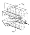
- La figure 1 représente schématiquement,en perspective, la disposition d'un laminoir quarto à cylindres déplaçables .
- La figure 2 est une vue partielle de dessus-d'un cylindre de travail et de ses moyens de déplacement.
- La figure 3 est une vue partielle de la cage du laminoir montrant les deux cylindres de travail et les dispositifs de cambrage, en coupe par un plan parallèle au plan de laminage et passant par les axes d'un jeu de vérins de cambrage dans une réalisation utilisant des poutres continues traversant la cage et ayant des extrémités en forme de T.
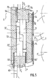
- La figure 4 est une vue partielle des dispositifs de cambrage, en coupe par un plan parallèle au plan de laminage et passant par les axes d'un jeu de vérins de cambrage dans la réalisation utilisant des pièces intermédiaires séparées en forme de T.
- La figure 5 montre la section particulière de ces pièces en coupe par un plan transversal,les empoises étant écartées l'une de l'autre.
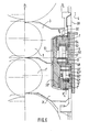
- La figure 6 est une vue des empoises des deux cylindres de travail et des dispositifs de cambrage en coupe par un plan perpendiculaire au plan de laminage et passant par les axes des vérins de cambrage.
- La figure 7 donne un schéma hydraulique du dispositif d'équilibrage dans un mode de réalisation plus perfectionné.
- Figure 1 shows schematically, in perspective, the arrangement of a quarto rolling mill with movable cylinders.
- Figure 2 is a partial top view of a working cylinder and its displacement means.
- Figure 3 is a partial view of the rolling mill cage showing the two working rolls and the bending devices, in section through a plane parallel to the rolling plane and passing through the axes of a set of bending cylinders in one embodiment using continuous beams crossing the cage and having T-shaped ends
- Figure 4 is a partial view of the bending devices, in section through a plane parallel to the rolling plane and passing through the axes of a set of bending cylinders in the embodiment using separate intermediate parts in the shape of a T.
- Figure 5 shows the particular section of these parts in section through a transverse plane, the chocks being spaced from one another.
- FIG. 6 is a view of the chocks of the two working rolls and of the bending devices in section through a plane perpendicular to the rolling plane and passing through the axes of the bending cylinders.
- FIG. 7 gives a hydraulic diagram of the balancing device in a more improved embodiment.
Sur la figure 1,on a représenté schématiquement un laminoir quarto comprenant deux cylindres de travail (1) et (1ʹ) et deux cylindres d'appui (2) et (2ʹ).Les axes des cylindres sont parallèles et disposés le long d'un plan de serrage P1 passant par les génératrices de contact.In Figure 1, there is shown schematically a quarto rolling mill comprising two working rolls (1) and (1ʹ) and two support rolls (2) and (2ʹ) .The axes of the cylinders are parallel and arranged along a clamping plane P1 passing through the contact generatrices.
Le produit laminé 20 passe entre les cylindres de travail (1) et (1ʹ) et son plan médian correspond sensiblement au plan transversal de symétrie P2 de l'ensemble de la cage de laminoir et notamment des cylindres d'appui (2) et (2ʹ). Normalement, les cylindres sont tous alignés et centrés sur le même plan médian P2. Cependant, pour les raisons indiquées plus haut les cylindres de travail (1) et (1ʹ) peuvent être déplacés axialement par rapport à la position de centrage de telle sorte que leur plan de symétrie transversal respectif se trouve décalé d'un côté ou de l'autre par rapport au plan médian P2. A cet effet, on applique sur les cylindres de travail (1) et (1ʹ) un effort de déplacement axial F1 dans un sens ou dans l'autre .The rolled product 20 passes between the working rolls (1) and (1ʹ) and its median plane corresponds substantially to the transverse plane of symmetry P2 of the whole of the rolling mill stand and in particular of the support rolls (2) and ( 2ʹ). Normally, the cylinders are all aligned and centered on the same median plane P2. However, for the reasons indicated above, the working rolls (1) and (1ʹ) can be moved axially relative to the centering position so that their respective transverse plane of symmetry is offset by one side or by one. other with respect to the median plane P2. To this end, an axial displacement force F1 is applied in one direction or the other to the working cylinders (1) and (1ʹ).
D'autre part, selon une autre disposition connue , des efforts de cambrage F2 sont appliqués sur les extrémités des arbres des cylindres de travail (1) et (1ʹ) , par l'intermédiaire de leurs empoises de façon à réaliser un cambrage du cylindre correspondant.On the other hand, according to another known arrangement, cambering forces F2 are applied to the ends of the shafts of the working cylinders (1) and (1ʹ), by means of their chocks so as to camber the cylinder. corresponding.
Grâce aux dispositions selon l'invention, les cylindres de travail (1) et (1ʹ) peuvent être soumis en même temps à un effort de déplacement axial F1 et aux efforts de cambrage F2.Thanks to the arrangements according to the invention, the working rolls (1) and (1ʹ) can be subjected at the same time to an axial displacement force F1 and to the bending forces F2.
Sur la figure 2,on a représenté une extrémité d'un cylindre de travail avec une empoise , et un dispositif de déplacement axial.Le cylindre de travail (1) est muni à ses deux extrémités de tourillons centrés, par l'intermédiaire de roulements , à l'intérieur d'empoises (3) formant corps de palier et montées coulissantes,parallèlement au plan de serrage P1, dans des fenêtres (40) ménagées dans les deux montants (4) de la cage de laminoir.FIG. 2 shows an end of a working cylinder with a chock, and an axial displacement device. The working cylinder (1) is provided at its two ends with centered pins, by means of bearings , inside chocks (3) forming a body bearing and sliding mounted, parallel to the clamping plane P1, in windows (40) formed in the two uprights (4) of the rolling stand.
A cet effet , comme on l'a représenté sur la figure 5,chaque empoise (3) du cylindre de travail 1 est munie de faces de glissement (31) parallèles au plan de serrage P1 et qui peuvent coulisser le long de faces correspondantes (51) ménagées vers l'intérieur sur des blocs de support (5) fixées dans les fenêtres (40) de la cage (4) du laminoir.To this end, as shown in FIG. 5, each chock (3) of the working
De la sorte, chaque empoise (3) guidée entre les deux faces verticales (51) peut se déplacer selon deux directions , d'une part verticalement sous l'action du dispositif de cambrage et d'autre part parallèlement à l'axe (10) du cylindre sous l'action du dispositif de réglage axial.In this way, each chock (3) guided between the two vertical faces (51) can move in two directions, on the one hand vertically under the action of the bending device and on the other hand parallel to the axis (10 ) of the cylinder under the action of the axial adjustment device.
On connaît différents dispositifs de déplacement axial des cylindres qui ne constituent pas l'objet de l'invention et qu'il n'est donc pas utile de décrire en détail .Various devices are known for axial displacement of the cylinders which do not constitute the subject of the invention and which it is therefore not useful to describe in detail.
D'une façon générale, l'effort de déplacement axial qui est appliqué sur l'une des empoises doit s'exercer exactement dans l'axe du cylindre et , à cet effet, on peut utiliser , par exemple, un vérin unique prenant appui sur un palonnier permettant d'appliquer l'effort de déplacement axial sur les deux côtés de l'empoise .In general, the axial displacement force which is applied to one of the chocks must be exerted exactly in the axis of the cylinder and, for this purpose, one can use, for example, a single jack supported on a lifting beam making it possible to apply the axial displacement force on the two sides of the chock.
Cependant , si le cylindre déplacé est un cylindre moteur , on peut aussi, comme on l'a représenté sur la figure 2 , utiliser des vérins de déplacement (42) alimentés en synchronisme et placés symétriquement de part et d'autre du moyen (43) d'entraînement en rotation du cylindre (1),l'empoise (3)étant munie, de chaque côté de l'axe (10),de pattes d'accrochage (35) qui s'engagent dans des têtes d'accrochage correspondantes solidaires de la tige de chaque vérin (42). Cet accrochage peut avantageusement se réaliser de façon amovible par déplacement latéral du vérin de déplacement (42) comme on l'a représenté sur la figure 2 pour le vérin de droite .However, if the displaced cylinder is a driving cylinder, it is also possible, as shown in FIG. 2, to use displacement cylinders (42) supplied in synchronism and placed symmetrically on either side of the means (43 ) driving the cylinder in rotation (1), the chock (3) being provided, on each side of the axis (10), hooking lugs (35) which engage in corresponding hooking heads integral with the rod of each jack (42). This attachment can advantageously be carried out in a removable manner by lateral displacement of the displacement cylinder (42) as shown in FIG. 2 for the right cylinder.
D'autre part, chaque empoise (3) d'un cylindre (1) est solidarisée avec ce dernier dans le sens axial par l'intermédiaire d'une coiffe (13) de fermeture de la cage du roulement , ce dernier étant réalisé de façon à pouvoir encaisser des efforts axiaux , par exemple des roulements coniques De la sorte , l'effort de déplacement axial appliqué par les vérins (42) sur l'une des empoises (3) est transmis au cylindre de travail et à la seconde empoise placée à l'autre extrémité de ce dernier .On the other hand, each chock (3) of a cylinder (1) is secured to the latter in the axial direction by means of a cap (13) for closing the bearing cage, the latter being made of so as to be able to withstand axial forces, for example tapered bearings In this way, the axial displacement force applied by the jacks (42) on one of the chocks (3) is transmitted to the working cylinder and to the second chock placed at the other end of the latter.
Chaque empoise (3) est d'autre part associée à un ensemble de cambrage qui, comme on l'a représenté schématiquement sur la figure 6, est constitué généralement de deux paires de vérins (6ª, 66ª) et (6b, 66b )placés respectivement de part et d'autre du plan de serrage P1 sur lequel est centré l'axe du cylindre 1.Each chock (3) is also associated with a cambering assembly which, as shown schematically in Figure 6, generally consists of two pairs of jacks (6ª, 66ª) and (6 b , 66 b ) placed respectively on either side of the clamping plane P1 on which the axis of
On sait que l'on peut réaliser, soit un cambrage dit "positif" dans lequel les empoises opposées des deux cylindres de travail s'écartent l'une de l'autre, soit un cambrage "négatif" pour lequel les empoises opposées se rapprochent . Cependant, il faut généralement s'opposer au rapprochement des empoises qui entraîne un écrasement des bords de la tôle par rapport à la partie centrale et c'est pourquoi, dans le cas le plus courant représenté sur les figures , on réalise seulement un cambrage positif c'est-à-dire dans le sens d'écartement des empoises par rapport au plan de passage de la tôle , selon les flèches F₂ de la figure 1 .We know that we can achieve either a so-called "positive" bending in which the opposite chocks of the two working rolls deviate from each other, or a "negative" bending for which the opposite chocks are close together . However, it is generally necessary to oppose the approximation of chocks which results in crushing of the edges of the sheet relative to the central part and this is why, in the most current shown in the figures, only positive bending is carried out, that is to say in the direction of spacing of the chocks with respect to the plane of passage of the sheet, according to the arrows F₂ in FIG. 1.
A cet effet, comme on le voit sur la figure 6 chaque empoise 3 est prolongée au-delà des faces de glissement (31) par des parties d'appui (32) en forme d'oreilles qui s'étendent au-dessus du bloc de support (5) dans lequel sont logés les vérins de cambrage (6). Cependant,l'effort de cambrage n'est pas appliqué directement sur les empoises (3) ,mais sur des pièces intermédiaires (7) qui sont interposées entre les vérins de cambrage (6) et les parties d'appui correspondantes (32).To this end, as can be seen in FIG. 6, each
Chaque bloc de support (5) est commun pour les deux cylindres de travail (1) et (1ʹ) et comprend, à chaque extrémité , en haut et en bas , un évidement transversal (52) limité par deux faces espacées (54) parallèles au plan de serrage . Chaque pièce intermédiaire (7) est munie d'une partie horizontale externe (70) logée dans l'évidement (52) et guidée en translation le long de faces de glissements correspondantes sur les deux faces opposées (54) du logement (52).Each support block (5) is common for the two working cylinders (1) and (1ʹ) and comprises, at each end, at the top and at the bottom, a transverse recess (52) limited by two spaced parallel faces (54) at the clamping plane. Each intermediate piece (7) is provided with an external horizontal part (70) housed in the recess (52) and guided in translation along corresponding sliding faces on the two opposite faces (54) of the housing (52).
De préférence,chaque pièce intermédiaire (7) a la forme d'un T, la partie externe (70) formant deux ailes horizontales (75) qui s'étendent symétriquement de part et d'autre d'une partie centrale verticale (73) centrée dans le plan médian P3 du bloc de support (5) perpendiculaire au plan de serrage P1 c'est-à-dire le plan vertical de symétrie des deux paires de vérins de cambrage dans lequel est centrée l'empoise (3) de chacun des deux cylindres de travail (1 et 1ʹ) lorsque ces derniers sont eux-mêmes alignés et centrés sur le plan médian P2 de la cage.Preferably, each intermediate part (7) has the shape of a T, the external part (70) forming two horizontal wings (75) which extend symmetrically on either side of a vertical central part (73) centered in the median plane P3 of the support block (5) perpendicular to the clamping plane P1 that is to say the vertical plane of symmetry of the two pairs of camber cylinders in which the chock (3) of each is centered of two working cylinders (1 and 1ʹ) when the latter are themselves aligned and centered on the median plane P2 of the cage.
Les deux vérins de cambrage (6ª , 66ª ) symétriques par rapport au plan P3, sont constitués chacun par un piston (62) monté coulissant verticalement dans un alésage (67) ménagé dans le bloc de support (5).The two camber cylinders (6ª, 66ª) symmetrical with respect to the plane P3, each consist of a piston (62) slidably mounted vertically in a bore (67) formed in the support block (5).
La partie centrale verticale (73) de la pièce intermédiaire (7) s'étend verticalement entre les deux vérins (6ª, 66ª ) et s'engage dans un usinage (53) formant un puit central ménagé dans le bloc de support (5) entre les alésages (67) des deux vérins (6a, 66ª) et qui prolonge l'évidement transversal (52) dans lequel s'étendent les deux ailes (75) de la pièce intermédiaire (7) pour passer au-dessus des deux vérins (6ª, 66ª).The vertical central part (73) of the intermediate piece (7) extends vertically between the two cylinders (6ª, 66ª) and engages in a machining (53) forming a central well formed in the support block (5) between the bores (67) of the two cylinders (6a, 66ª) and which extends the transverse recess (52) in which extend the two wings (75) of the intermediate piece (7) to pass over the two cylinders (6ª, 66ª).
La pièce centrale (73) constitue un pied de guidage de la pièce intermédiaire (7) monté coulissant verticalement entre deux faces de guidage (55) parallèles au plan P3 et écartées symétriquement de part et d'autre de celui-ci et qui constituent les deux faces opposées de l'usinage central (53).The central part (73) constitutes a foot for guiding the intermediate part (7) mounted to slide vertically between two guide faces (55) parallel to the plane P3 and symmetrically spaced apart on either side of it and which constitute the two opposite sides of the central machining (53).
La même disposition est adoptée pour les vérins (6ʹª , 66ʹª ) de cambrage du cylindre inférieur (1ʹ). Le bloc de support (5) qui est commun pour les deux cylindres de travail (1 et 1ʹ) est donc symétrique, d'une part ,par rapport au plan vertical P3 et d'autre part, par rapport à un plan horizontal .The same arrangement is adopted for the cylinders (6ʹª, 66ʹª) for bending the lower cylinder (1ʹ). The support block (5) which is common for the two working cylinders (1 and 1ʹ) is therefore symmetrical, on the one hand, with respect to the vertical plane P3 and on the other hand, with respect to a horizontal plane.
Pour réaliser les ensembles de cambrage (6 et 6ʹ ) associés aux deux cylindres , on ménage donc dans le bloc (5) , de chaque côté du plan de symétrie P3 , deux alésages (67 et 67ʹ) séparés par une cloison centrale (68) et s'ouvrant dans les évidements transversaux (52 , 52ʹ) ménagés sur les deux faces ,respectivement supérieure et inférieure ,du bloc (5) et dans lesquels s'engagent les parties supérieures (70, 70ʹ) des deux pièces intermédiaires (7, 7ʹ) sur lesquelles s'appuient respectivement les empoises (3 et 3ʹ) des deux cylindres de travail (1 et 1ʹ).Chaque alésage (67) est fermé de façon étanche par une cloison (63) qui constitue le fond de l'évidement transversal (52) et limite la chambre du vérin (6) fermée, du côté opposé, par la cloison 68 et à l'intérieur de laquelle coulisse le piston (61) prolongé par une tige (62) qui traverse la cloison (63) pour s'appuyer sur l'aile correspondante (75) de la pièce intermédiaire (7).To make the cambering assemblies (6 and 6ʹ) associated with the two cylinders, there are therefore housed in the block (5), on each side of the plane of symmetry P3, two bores (67 and 67ʹ) separated by a central partition (68) and opening in the transverse recesses (52, 52ʹ) formed on the two faces, respectively upper and lower, of the block (5) and in which engage the upper parts (70, 70ʹ) of the two intermediate parts (7, 7ʹ) on which the chocks (3 and 3ʹ) of the two working rolls (1 and 1ʹ) are supported respectively. Each bore (67) is sealed by a partition (63) which constitutes the bottom of the transverse recess (52) and limits the chamber of the jack (6) closed, on the opposite side, by the
Les deux paires de vérins (6ª, 66ª ) (6ʹª, 66ʹa) ainsi ménagés sur les deux faces du bloc de support (5) peuvent être alimentés par des circuits hydrauliques tels que représentés sur la figure 7 , la pièce de support (5) constituant ainsi un véritable bloc hydraulique fixe .The two pairs of jacks (6ª, 66ª) (6ʹª, 66ʹa) thus formed on the two faces of the support block (5) can be supplied by hydraulic circuits as shown in FIG. 7, the support part (5) thus constituting a real fixed hydraulic block.
Par ailleurs, l'oreille d'appui (32) de l'empoise (3) prend appui , par l'intermédiaire d'un grain de poussée (33) sur une face lisse (76) ménagée sur la partie externe (70) de la pièce intermédiaire (7) et le long de laquelle le grain de poussée (33) peut donc glisser de façon continue en suivant les déplacements axiaux du cylindre 1 .Furthermore, the support lug (32) of the chock (3) is supported, by means of a thrust grain (33) on a smooth face (76) formed on the external part (70) of the intermediate piece (7) and along which the thrust grain (33) can therefore slide continuously following the axial displacements of the
Le grain de poussée (33) est placé dans le plan de symétrie transversal de l'empoise (3) et est donc centré dans le plan P3 dans la position représentée sur la figure 4 pour laquelle les cylindres de travail (1) et (1ʹ) sont alignés et centrés dans le plan médian P2 de la cage .The thrust grain (33) is placed in the transverse plane of symmetry of the chock (3) and is therefore centered in the plane P3 in the position shown in FIG. 4 for which the working rolls (1) and (1ʹ ) are aligned and centered in the median plane P2 of the cage.
Du fait que le bloc de support (5) est commun pour les deux systèmes de cambrage (6 et 6ʹ) des deux cylindres de travail (1 et 1ʹ) , les parties centrales formant pied de guidage (73, 73ʹ) des deux pièces intermédiaires (7, 7ʹ) s'engagent dans un même usinage (53) qui traverse complètement le bloc de support (5), dans l'axe de celui-ci , en reliant entre eux les évidements transversaux (52 et 52ʹ) et en passant entre les chambres des quatre vérins de cambrage.Because the support block (5) is common for the two cambering systems (6 and 6ʹ) of the two working cylinders (1 and 1ʹ), the central parts forming the guide foot (73, 73ʹ) of the two intermediate parts (7, 7ʹ) engage in the same machining (53) which completely crosses the support block (5), in the axis thereof, connecting between them the transverse recesses (52 and 52 entre) and passing between the chambers of the four camber cylinders.
Comme on l'a représenté sur la figure 5 , le pied de guidage (73) de chaque pièce intermédiaire (7, 7ʹ) est muni , à son extrémité opposée à la partie externe (70), d'une échancrure en forme de L qui ménage une partie amincie (74) décalée latéralement de sorte que les deux pieds de guidage (73, 73ʹ) peuvent se chevaucher dans la partie médiane de l'usinage central (53). De la sorte , chaque pied de guidage (73, 73ʹ) peut être guidé pratiquement tout le long des faces de guidage (55) ménagées sur toute la hauteur de l'usinage central (53).As shown in FIG. 5, the guide foot (73) of each intermediate part (7, 7ʹ) is provided, at its end opposite to the external part (70), with an L-shaped notch which spares a thinned part (74) offset laterally so that the two guide feet (73, 73ʹ) can overlap in the middle part of the central machining (53). In this way, each guide foot (73, 73ʹ) can be guided practically all along the guide faces (55) formed over the entire height of the central machining (53).
Par ailleurs, dans le sens axial, les deux parties d'appui (33) de chaque empoise sont également centrées dans des plans de poussée P4 parallèles au plan de serrage P1 et passant par les axes des deux vérins de cambrage correspondants.Furthermore, in the axial direction, the two support parts (33) of each chock are also centered in thrust planes P4 parallel to the clamping plane P1 and passing through the axes of the two corresponding camber cylinders.
Comme on le voit sur la figure 5, les plans de poussée P4 , Pʹ4 des deux ensembles de cambrage associés aux empoises (3 et 3ʹ) et placés dans un même bloc de support 5 sont décalés de part et d'autre du plan de symétrie du bloc de support 5 sur lequel est centré l'usinage (53) .As can be seen in FIG. 5, the thrust planes P4, Pʹ4 of the two cambering assemblies associated with the chocks (3 and 3ʹ) and placed in the same support block 5 are offset on either side of the plane of symmetry of the support block 5 on which the machining is centered (53).
Lorsque, au moyen des vérins (42), on commande un déplacement axial de l'un des cylindres , par exemple le cylindre de travail (1), le grain de poussée (33) correspondant glisse sur la face lisse (76) de la pièce intermédiaire (7) d'un côté ou de l'autre du plan de symétrie P3 . Si , en meme temps , on exerce un effort de cambrage sur le cylindre, chaque pièce de glissement (7) se déplace verticalement grâce à son pied de guidage (73) qui s'oppose au moment de renversement résultant du décalage du grain de poussée (33) par rapport au plan de symétrie des efforts exercés par les vérins.When, by means of the jacks (42), an axial displacement of one of the cylinders is controlled, by example the working cylinder (1), the corresponding thrust grain (33) slides on the smooth face (76) of the intermediate piece (7) on one side or the other of the plane of symmetry P3. If, at the same time, a cambering force is exerted on the cylinder, each sliding part (7) moves vertically thanks to its guide foot (73) which opposes the moment of overturning resulting from the shifting of the thrust grain (33) relative to the plane of symmetry of the forces exerted by the jacks.
L'invention permet donc de réaliser en même temps le réglage axial et le cambrage d'un cylindre de travail et, si les déplacements axiaux restent réduits, comme c'est le cas le plus souvent, le moment de renversement de la pièce intermédiaire (7) qui en résulte peut être encaissé facilement par l'effet d'encastrement du pied de guidage (7) .The invention therefore makes it possible to carry out at the same time the axial adjustment and the bending of a working cylinder and, if the axial displacements remain reduced, as is most often the case, the moment of overturning of the intermediate part ( 7) which results can be easily collected by the embedding effect of the guide foot (7).
On évite ainsi d'augmenter les pressions sur les surfaces de guidage vertical qui pourraient augmenter les frottements et pénaliser les performances de la régulation d'épaisseur.This avoids increasing the pressures on the vertical guide surfaces which could increase friction and penalize the performance of the thickness regulation.
Toutefois, si l'on désire effectuer des déplacements axiaux plus importants le moment de renversement qui en résulte peut se traduire par des efforts de frottement excessifs susceptibles de perturber le déplacement de l'empoise . Il est alors préférable d'adjoindre à l'effet d'encastrement du pied de guidage d'autres dispositions permettant de réduire les frottements en équilibrant les efforts appliqués.However, if it is desired to make greater axial displacements, the resulting overturning moment can result in excessive friction forces liable to disturb the movement of the chock. It is then preferable to add to the embedding effect of the guide foot other provisions making it possible to reduce friction by balancing the applied forces.
Divers moyens peuvent être employés à cet effet .Various means can be used for this purpose.
C'est ainsi que, dans le mode de réalisation représenté sur la figure 3, les pièces intermédiaires (7) et (7ª) correspondant aux deux empoises (3) et (3ª) de chaque cylindre (1) et qui sont placées au même niveau par rapport à l'axe du cylindre, sont solidaires d'une poutre (77) s'étendant le long du cylindre, parallèlement à son axe. Cette poutre (77) peut être dimensionnée de façon à encaisser les moments de renversement des pièces (7) et (7a) dus au déplacement des empoises (3) et (3a).Thus, in the embodiment shown in Figure 3, the intermediate parts (7) and (7ª) corresponding to the two chocks (3) and (3ª) of each cylinder (1) and which are placed at the same level with respect to the axis of the cylinder, are integral with a beam (77) extending along the cylinder, parallel to its axis. This beam (77) can be dimensioned so as to absorb the moments of overturning of the parts (7) and (7a) due to the movement of the chocks (3) and (3a).
Cette disposition simple peut cependant présenter un inconvénient dans la mesure où les quatre poutres (77) s'étendent entre les deux montants de la cage, à proximité des cylindres de travail, c'est-à-dire dans un espace que l'on a intérêt à dégager .This simple arrangement can however have a drawback insofar as the four beams (77) extend between the two uprights of the cage, near the working rolls, that is to say in a space which is has an interest in clearing.
C'est pourquoi, dans un mode de réalisation préférentiel, on réalise un équiligrage des efforts appliqués par les vérins de cambrage en fonction de la position de l'empoise correspondante .This is why, in a preferred embodiment, a balancing of the forces applied by the bending cylinders is carried out as a function of the position of the corresponding chock.
Selon l'une des caractéristiques essentielles de l'invention, on mesure le décalage du cylindre déplacé (1) par rapport au plan médian P2 de la cage au moyen d'un capteur de déplacement (44) constitué de deux parties coulissant l'une par rapport à l'autre , fixées, par exemple sur les deux parties de l'un des vérins (42) et fournissant un signal analogique ou digital proportionnel au décalage du cylindre de travail par rapport à la position de centrage dans le plan médian P2 et de signe correspondant au sens du décalage . Ce signal est utilisé pour l'équilibrage des pressions dans les vérins de cambrage grâce à un dis positif (8) représenté schématiquement sur la figure 7.According to one of the essential characteristics of the invention, the offset of the displaced cylinder (1) is measured relative to the median plane P2 of the cage by means of a displacement sensor (44) consisting of two sliding parts, one relative to the other, fixed, for example on the two parts of one of the jacks (42) and providing an analog or digital signal proportional to the offset of the working cylinder relative to the centering position in the median plane P2 and of sign corresponding to the direction of the shift. This signal is used for balancing the pressures in the camber cylinders by means of a dis positive (8) shown diagrammatically in FIG. 7.
Sur cette figure, on a représenté à titre d'exemple un cylindre déplaçable (1) et ses deux dispositifs de cambrage constitués chacun de deux ensembles de vérins placés dans des blocs hydrauliques (5a, 5b, 5ʹc, 5ʹd) chaque ensemble comprenant deux vérins (6a, 66ª), (6b, 66b), (6ʹa, 66ʹa) (6ʹb, 66ʹb).In this figure, there is shown by way of example a displaceable cylinder (1) and its two bending devices each consisting of two sets of jacks placed in hydraulic blocks (5a, 5b, 5ʹc, 5ʹd) each set comprising two jacks (6a, 66ª), (6b, 66b), (6ʹa, 66ʹa) (6ʹb, 66ʹb).
Par convention, la référence 6 est attribuée aux vérins de cambrage , placés du côté du cylindre , c'est-à-dire vers l'intérieur de la cage et la référence 66 aux vérins placés vers l'extérieur .By convention, the
Les quatre vérins associés à chaque empoise sont disposés de la façon décrite précédemment et sont centrés dans deux plans transversaux R3 et R4 écartés l'un de l'autre d'une distance e.The four jacks associated with each chock are arranged in the manner described above and are centered in two transverse planes R3 and R4 spaced from each other by a distance e.
Les blocs hydrauliques (5a, 5b) et (5c, 5d) des deux empoises sont reliés par un circuit unique d'alimentation (80) à une source de fluide sous pression non représentée mais le circuit (80) se divise en deux branches (81) et (82) permettant d'alimenter à la même pression les vérins placés du même côté de l'empoise dans le sens de déplacement axial. La branche (81) alimente donc en parallèle les vérins (6ª, 6b, ) et (66c,66d )des deux files R3 et Rʹ4 placées sur la droite sur la figure 7 alors que la branche 82 alimente en parallèle les vérins (66ª, 66b, ) et (6c , 6d ) des deux files R4 et Rʹ3 placées sur la gauche .The hydraulic blocks (5a, 5b) and (5c, 5d) of the two chocks are connected by a single supply circuit (80) to a source of pressurized fluid not shown but the circuit (80) is divided into two branches ( 81) and (82) allowing the cylinders placed on the same side of the chock in the direction of axial displacement to be supplied at the same pressure. The branch (81) therefore supplies the jacks (6ª, 6 b ,) and (66 c , 66 d ) in parallel of the two rows R3 and Rʹ4 placed on the right in FIG. 7 while the
Le circuit hydraulique est prévu pour que , quelles que soient les pressions ,tous les vérins soient alimentés avec un même débit de façon à déterminer des déplacements égaux à la même vitesse.The hydraulic circuit is designed so that, whatever the pressures, all the cylinders are supplied with the same flow rate so as to determine equal displacements at the same speed.
Chaque branche (81), (82) du circuit d'alimentation (8) est munie d'un régulateur de pression (83) qui, en fonction des signaux reçus sur son entrée (84) règle la pression dans le circuit correspondant mais en y maintenant un débit constant.Each branch (81), (82) of the supply circuit (8) is provided with a pressure regulator (83) which, depending on the signals received on its input (84) regulates the pressure in the corresponding circuit but in maintaining a constant flow.
Chaque cylindre (1) est associé à un capteur (44) des déplacements axiaux fournissant un signal analogique ou digital proportionnel au déplacement et qui est appliqué sur une unité de calcul (85) .Each cylinder (1) is associated with an axial displacement sensor (44) providing an analog or digital signal proportional to the displacement and which is applied to a calculation unit (85).
A partir des signaux reçus, celle-ci élabore les consignes de pression S1 et S2 appliquées aux entrées (84) des régulateurs de pression (83) des deux branches (81) et (82) en fonction d'une loi programmée à l'avance permettant d'assurer une répartition des pressions P1 et p2 telle que la somme des moments résultants des efforts de poussée appliqués par les vérins de cambrage dans les plans P4 et de la réaction de la partie d'appui 32 de l'empoise correspondante sur la pièce en forme de T soit nulle . De la sorte,même en position de centrage des cylindres (1) dans le plan médian P2 de la cage , les deux files de vérins R3 et R4 peuvent ne pas être symétriques par rapport au plan médian P5 du roulement de l'empoise et ceci permet de disposer les vérins de la façon la plus adéquate à l'intérieur des blocs hydrauliques (5) dont le plan de symétrie ne coïncide pas obligatoirement avec celui du roulement.On the basis of the signals received, the latter develops the pressure setpoints S1 and S2 applied to the inputs (84) of the pressure regulators (83) of the two branches (81) and (82) according to a law programmed in the advance to ensure a distribution of pressures P1 and p2 such that the sum of the moments resulting from the thrust forces applied by the camber cylinders in the planes P4 and the reaction of the
Bien entendu, l'invention ne se limite pas aux détails du mode de réalisation qui vient d'être décrit, des variantes pouvant être imaginées en employant notamment des moyens équivalents sans s'écarter du cadre de protection défini par les revendications .Of course, the invention is not limited to the details of the embodiment which has just been described, variants which can be imagined by employing in particular equivalent means without departing from the protective framework defined by the claims.
En particulier, les différents organes utilisés pour l'équilibrage des pressions pourraient être remplacés par des moyens remplissant les mêmes fonctions , ces moyens pouvant être hydrauliques, électriques ou même mécaniques (came, bras de levier, etc...) . D'une façon générale, toute technologie de mesure des déplacements, de calcul des corrections et d'équilibrage des pressions peut être utilisée pour obtenir le résultat recherché.In particular, the various members used for balancing the pressures could be replaced by means fulfilling the same functions, these means being able to be hydraulic, electric or even mechanical (cam, lever arm, etc.). In general, any technology for measuring displacements, calculating corrections and balancing pressures can be used to obtain the desired result.
On notera aussi que, comme on l'a indiqué sur la partie gauche de la figure 6, les dispositifs fixes de cambrage selon l'invention peuvent s'adapter à différents diamètres de cylindres et/ou s'adapter à une variation du diamètre due à l'usure, dans la limite de la course des vérins.It will also be noted that, as indicated on the left-hand side of FIG. 6, the fixed bending devices according to the invention can adapt to different diameters of cylinders and / or adapt to a variation in the diameter due wear, within the limit of the cylinder stroke.
Enfin, on a décrit l'invention dans le cas d'un laminoir avec cambrage positif seul mais les mêmes dispositions pourraient être utilisées pour réaliser le cambrage de chaque cylindre dans les deux sens positif et négatif .Finally, the invention has been described in the case of a rolling mill with positive bending alone, but the same arrangements could be used to bend each cylinder in both positive and negative directions.
Sans modifier sensiblement le mode de réalisation précédemment décrit, il suffirait, par exemple, d'utiliser des vérins à double effet dont les tiges seraient fixées aux oreilles d'appui des empoises pour agir dans un sens ou dans l'autre.Without appreciably modifying the embodiment described above, it would suffice, for example, to use double-acting jacks whose rods are fixed to the support ears of the chocks to act in one direction or the other.
Mais on pourrait aussi, dans une autre disposition, utiliser des vérins à simple effet placés par paires de part et d'autre de la partie d'appui de l'empoise, chaque paire de vérins étant associée à une pièce de glissement en T.But we could also, in another arrangement, use single-acting cylinders placed in pairs on either side of the support part of the chock, each pair of cylinders being associated with a T-shaped sliding part.
Les signes de référence insérés après les caractéristiques techniques mentionnées dans les revendications, ont pour seul but de faciliter la compréhension de ces dernières, et n'en limitent aucunement la portée.The reference signs inserted after the technical characteristics mentioned in the claims, have the sole purpose of facilitating the understanding of the latter, and in no way limit their scope.
Claims (17)
caractérisé par le fait que chaque ensemble (6) de vérins de cambrage prend appui dans le sens de l'effort de cambrage sur une pièce de glissement (7) montée coulissante verticalement entre deux paires de faces de guidage (54) (55) respectivement parallèles, et perpendiculaires au plan de serrage (P1), ménagées dans un usinage (52) (53) réalisé à l'intérieur du bloc de support (5) et que la partie d'appui (32) correspondante de l'empoise (3) prend appui avec possibilité de glissement sur une face plane et lisse (76) ména gée sur ladite pièce de glissement (7) du côté opposé aux vérins de cambrage (6) et parallèle à l'axe du cylindre (1).1. Rolling mill with axially displaceable cylinders comprising, inside a support cage (4), at least two working rolls (1,1ʹ) resting on a clamping plane P1, on at least two cylinders d 'support (2,2ʹ) and whose ends are carried, by means of bearings in chocks (3,3ʹ) slidably mounted in the support cage, parallel to the clamping plane, at least one of the cylinders of work (1) being associated, on the one hand with means (42) for moving said cylinder (1) along its axis (10) on either side of a position for centering the working cylinders on the median plane P2 of the cage (4) and on the other hand means (6) for bending said cylinder (1) comprising, for each chock (3) two symmetrical assemblies of at least two bending cylinders (6) spaced apart 'from each other in the axial direction, and acting respectively on support parts (32) formed on each side of the chock (3), said sets of jacks being placed inside a support block (5) secured to the cage,
characterized in that each set (6) of cambering cylinders bears in the direction of the cambering force on a sliding part (7) slidably mounted vertically between two pairs of guide faces (54) (55) respectively parallel, and perpendicular to the clamping plane (P1), formed in a machining (52) (53) produced inside the support block (5) and that the corresponding support part (32) of the chock ( 3) is supported with the possibility of sliding on a flat and smooth face (76) mena gée on said sliding part (7) on the side opposite to the camber cylinders (6) and parallel to the axis of the cylinder (1).
Applications Claiming Priority (2)
| Application Number | Priority Date | Filing Date | Title |
|---|---|---|---|
| FR8702706 | 1987-02-27 | ||
| FR8702706A FR2611541B1 (en) | 1987-02-27 | 1987-02-27 | DEVICE FOR ADJUSTING THE PROFILE AND DISTRIBUTION OF WEAR OF CYLINDERS IN A ROLLER WITH AXIALLY MOVABLE CYLINDERS |
Publications (3)
| Publication Number | Publication Date |
|---|---|
| EP0283342A1 true EP0283342A1 (en) | 1988-09-21 |
| EP0283342B1 EP0283342B1 (en) | 1992-04-29 |
| EP0283342B2 EP0283342B2 (en) | 1997-01-22 |
Family
ID=9348449
Family Applications (1)
| Application Number | Title | Priority Date | Filing Date |
|---|---|---|---|
| EP88400372A Expired - Lifetime EP0283342B2 (en) | 1987-02-27 | 1988-02-18 | Rolling mill having axially shifting rolls, and roll profile control method |
Country Status (8)
| Country | Link |
|---|---|
| US (1) | US4934166A (en) |
| EP (1) | EP0283342B2 (en) |
| JP (1) | JPH0751244B2 (en) |
| BR (1) | BR8800841A (en) |
| CA (1) | CA1294464C (en) |
| DE (1) | DE3870495D1 (en) |
| ES (1) | ES2031250T5 (en) |
| FR (1) | FR2611541B1 (en) |
Cited By (5)
| Publication number | Priority date | Publication date | Assignee | Title |
|---|---|---|---|---|
| GB2202173B (en) * | 1987-03-19 | 1991-08-14 | Davy Mckee | Rolling mill |
| FR2710567A1 (en) * | 1993-09-28 | 1995-04-07 | Clecim Sa | Rolling mill with axial displacement. |
| WO2007121832A1 (en) * | 2006-04-21 | 2007-11-01 | Siemens Vai Metals Technologies Gmbh & Co | Bending device for two working rolls of a rolling stand |
| WO2012049183A1 (en) * | 2010-10-12 | 2012-04-19 | Sms Siemag Ag | Roll stand |
| EP3981522A4 (en) * | 2019-10-25 | 2022-06-29 | Primetals Technologies Japan, Ltd. | Rolling mill |
Families Citing this family (15)
| Publication number | Priority date | Publication date | Assignee | Title |
|---|---|---|---|---|
| FR2611541B1 (en) | 1987-02-27 | 1994-04-29 | Clecim Sa | DEVICE FOR ADJUSTING THE PROFILE AND DISTRIBUTION OF WEAR OF CYLINDERS IN A ROLLER WITH AXIALLY MOVABLE CYLINDERS |
| GB2279023B (en) * | 1993-04-27 | 1996-06-05 | Ward Building Systems Ltd | Rolling mill |
| US5448901A (en) * | 1994-05-03 | 1995-09-12 | The University Of Toledo | Method for controlling axial shifting of rolls |
| US5752404A (en) * | 1996-12-17 | 1998-05-19 | Tippins Incorporated | Roll shifting system for rolling mills |
| US5970771A (en) * | 1998-07-10 | 1999-10-26 | Danieli United | Continuous spiral motion system for rolling mills |
| AT407124B (en) * | 1998-10-19 | 2000-12-27 | Voest Alpine Ind Anlagen | BENDING DEVICE FOR TWO WORK ROLLS OF A ROLLING STAND |
| IT1315119B1 (en) * | 2000-09-25 | 2003-02-03 | Danieli Off Mecc | DEVICE AND METHOD FOR CURVING THE CYLINDERS OF A DILAMINATION CAGE. |
| DE10334682A1 (en) * | 2003-07-30 | 2005-02-17 | Sms Demag Ag | rolling device |
| US20070254230A1 (en) * | 2006-04-28 | 2007-11-01 | Xerox Corporation | External additive composition and process |
| DE102006051728B4 (en) * | 2006-10-30 | 2013-11-21 | Outokumpu Nirosta Gmbh | Method for rolling metal strips, in particular steel strips |
| DE102008035702A1 (en) * | 2008-07-30 | 2010-02-04 | Sms Siemag Aktiengesellschaft | rolling device |
| DE102008049179A1 (en) | 2008-09-26 | 2010-04-01 | Sms Siemag Aktiengesellschaft | rolling device |
| DE102009058876A1 (en) * | 2009-01-23 | 2010-07-29 | Sms Siemag Ag | Bending and balancing device for axially displaceable work rolls of a roll stand |
| ITMI20101502A1 (en) * | 2010-08-05 | 2012-02-06 | Danieli Off Mecc | INTEGRATED BENDING AND SHIFTING SYSTEM UNDER LOAD FOR CAGES WITH HIGH OPENING BETWEEN THE WORKING ROLLERS |
| ITMI20120598A1 (en) | 2012-04-12 | 2013-10-13 | Danieli Off Mecc | INTEGRATED BENDING AND BALANCING SYSTEM FOR LAMINATION CAGES |
Citations (6)
| Publication number | Priority date | Publication date | Assignee | Title |
|---|---|---|---|---|
| EP0067040A2 (en) * | 1981-06-03 | 1982-12-15 | Hitachi, Ltd. | Rolling mill |
| EP0084927A1 (en) * | 1982-01-06 | 1983-08-03 | Hitachi, Ltd. | Rolling mill |
| DE3331055A1 (en) * | 1983-08-29 | 1985-03-14 | SMS Schloemann-Siemag AG, 4000 Düsseldorf | Roll stand with axially displaceable work rolls |
| DE3529364A1 (en) * | 1985-08-16 | 1987-02-19 | Schloemann Siemag Ag | DRIVE DEVICE FOR THE AXIAL SHIFTING OF ROLLS OF A ROLLING DEVICE |
| EP0233460A2 (en) * | 1986-01-17 | 1987-08-26 | Sms Schloemann-Siemag Aktiengesellschaft | Roll bending device for axially shifting rolls of a multiple rolling stand |
| EP0238377A1 (en) * | 1986-02-14 | 1987-09-23 | Clecim | Roll bending control in a rolling mill with axially shiftable rolls |
Family Cites Families (19)
| Publication number | Priority date | Publication date | Assignee | Title |
|---|---|---|---|---|
| JPS5666307A (en) * | 1979-10-04 | 1981-06-04 | Hitachi Ltd | Rolling mill |
| JPS58141808A (en) * | 1982-02-19 | 1983-08-23 | Hitachi Ltd | Method and appratus for controlling sheet thickness in rolling mill |
| JPS5956910A (en) * | 1982-09-27 | 1984-04-02 | Kawasaki Steel Corp | Method for controlling pressing force for roll bending |
| JPS5987904A (en) * | 1982-11-12 | 1984-05-21 | Mitsubishi Heavy Ind Ltd | Work roll bending cylinder device |
| JPS59153504A (en) * | 1983-02-22 | 1984-09-01 | Ishikawajima Harima Heavy Ind Co Ltd | Rolling mill |
| JPS59185505A (en) * | 1983-04-05 | 1984-10-22 | Ishikawajima Harima Heavy Ind Co Ltd | Rolling mill |
| JPS606212A (en) * | 1983-06-23 | 1985-01-12 | Ishikawajima Harima Heavy Ind Co Ltd | Control device for rolling mill |
| JPS6018210A (en) * | 1983-07-13 | 1985-01-30 | Ishikawajima Harima Heavy Ind Co Ltd | Rolling mill |
| JPS6068103A (en) * | 1983-09-22 | 1985-04-18 | Ishikawajima Harima Heavy Ind Co Ltd | Rolling mill |
| DE3409221A1 (en) * | 1984-03-14 | 1985-09-19 | SMS Schloemann-Siemag AG, 4000 Düsseldorf | ROLLING MILLS WITH AXIAL SLIDING WORK ROLLERS |
| JPS619108U (en) * | 1984-06-19 | 1986-01-20 | 石川島播磨重工業株式会社 | rolling mill |
| JPS619107U (en) * | 1984-06-19 | 1986-01-20 | 石川島播磨重工業株式会社 | rolling mill |
| JPS6122940A (en) * | 1984-07-10 | 1986-01-31 | 日産自動車株式会社 | Interior finish material for automobile |
| JPH0616887B2 (en) * | 1985-06-06 | 1994-03-09 | 株式会社日立製作所 | Roll shape control device for rolling mill |
| JPH0679730B2 (en) * | 1985-07-08 | 1994-10-12 | 株式会社日立製作所 | Roll bending device |
| GB8528848D0 (en) * | 1985-11-22 | 1985-12-24 | Davy Mckee Poole | Rolling mills |
| DE3604195C2 (en) * | 1986-02-07 | 1994-05-19 | Mannesmann Ag | Roll stand with work or intermediate rolls that can be moved in the axial direction |
| FR2611541B1 (en) | 1987-02-27 | 1994-04-29 | Clecim Sa | DEVICE FOR ADJUSTING THE PROFILE AND DISTRIBUTION OF WEAR OF CYLINDERS IN A ROLLER WITH AXIALLY MOVABLE CYLINDERS |
| US4803865A (en) * | 1987-07-17 | 1989-02-14 | SMS Schloemann--Siemag Aktiengesellschaft | Stand-supported bending device for axially slidable rolls of a multiroll rolling mill |
-
1987
- 1987-02-27 FR FR8702706A patent/FR2611541B1/en not_active Expired - Fee Related
-
1988
- 1988-02-18 EP EP88400372A patent/EP0283342B2/en not_active Expired - Lifetime
- 1988-02-18 ES ES88400372T patent/ES2031250T5/en not_active Expired - Lifetime
- 1988-02-18 DE DE8888400372T patent/DE3870495D1/en not_active Expired - Lifetime
- 1988-02-23 CA CA000559565A patent/CA1294464C/en not_active Expired - Lifetime
- 1988-02-26 US US07/160,985 patent/US4934166A/en not_active Expired - Lifetime
- 1988-02-26 BR BR8800841A patent/BR8800841A/en unknown
- 1988-02-27 JP JP63045690A patent/JPH0751244B2/en not_active Expired - Fee Related
Patent Citations (6)
| Publication number | Priority date | Publication date | Assignee | Title |
|---|---|---|---|---|
| EP0067040A2 (en) * | 1981-06-03 | 1982-12-15 | Hitachi, Ltd. | Rolling mill |
| EP0084927A1 (en) * | 1982-01-06 | 1983-08-03 | Hitachi, Ltd. | Rolling mill |
| DE3331055A1 (en) * | 1983-08-29 | 1985-03-14 | SMS Schloemann-Siemag AG, 4000 Düsseldorf | Roll stand with axially displaceable work rolls |
| DE3529364A1 (en) * | 1985-08-16 | 1987-02-19 | Schloemann Siemag Ag | DRIVE DEVICE FOR THE AXIAL SHIFTING OF ROLLS OF A ROLLING DEVICE |
| EP0233460A2 (en) * | 1986-01-17 | 1987-08-26 | Sms Schloemann-Siemag Aktiengesellschaft | Roll bending device for axially shifting rolls of a multiple rolling stand |
| EP0238377A1 (en) * | 1986-02-14 | 1987-09-23 | Clecim | Roll bending control in a rolling mill with axially shiftable rolls |
Non-Patent Citations (1)
| Title |
|---|
| PATENT ABSTRACTS OF JAPAN, vol. 9, no. 135 (M-386)[1858], 11 juin 1985; & JP-A-60 018 210 (ISHIKAWAJIMA HARIMA JUKOGYO K.K.) 30-01-1985 * |
Cited By (9)
| Publication number | Priority date | Publication date | Assignee | Title |
|---|---|---|---|---|
| GB2202173B (en) * | 1987-03-19 | 1991-08-14 | Davy Mckee | Rolling mill |
| FR2710567A1 (en) * | 1993-09-28 | 1995-04-07 | Clecim Sa | Rolling mill with axial displacement. |
| EP0649686A1 (en) * | 1993-09-28 | 1995-04-26 | Clecim | Rolling mill with axially shifting rolls |
| CN1050541C (en) * | 1993-09-28 | 2000-03-22 | 克莱西姆公司 | Axial displacement rolling mill |
| WO2007121832A1 (en) * | 2006-04-21 | 2007-11-01 | Siemens Vai Metals Technologies Gmbh & Co | Bending device for two working rolls of a rolling stand |
| US8196444B2 (en) | 2006-04-21 | 2012-06-12 | Siemens Vai Metals Technologies Gmbh | Bending device for two working rolls of a rolling stand |
| CN101426595B (en) * | 2006-04-21 | 2012-07-11 | 西门子Vai金属技术有限责任公司 | Bending device for two working rolls of a rolling stand |
| WO2012049183A1 (en) * | 2010-10-12 | 2012-04-19 | Sms Siemag Ag | Roll stand |
| EP3981522A4 (en) * | 2019-10-25 | 2022-06-29 | Primetals Technologies Japan, Ltd. | Rolling mill |
Also Published As
| Publication number | Publication date |
|---|---|
| FR2611541B1 (en) | 1994-04-29 |
| ES2031250T3 (en) | 1992-12-01 |
| EP0283342B1 (en) | 1992-04-29 |
| FR2611541A1 (en) | 1988-09-09 |
| CA1294464C (en) | 1992-01-21 |
| EP0283342B2 (en) | 1997-01-22 |
| ES2031250T5 (en) | 1997-03-16 |
| US4934166A (en) | 1990-06-19 |
| DE3870495D1 (en) | 1992-06-04 |
| JPS63230208A (en) | 1988-09-26 |
| JPH0751244B2 (en) | 1995-06-05 |
| BR8800841A (en) | 1988-10-04 |
Similar Documents
| Publication | Publication Date | Title |
|---|---|---|
| EP0283342B1 (en) | Rolling mill having axially shifting rolls, and roll profile control method | |
| EP0238377B1 (en) | Roll bending control in a rolling mill with axially shiftable rolls | |
| EP1601474B1 (en) | Method for changing the configuration of a rolling mill and advanced rolling mill for carrying out said method | |
| FR2591919A1 (en) | MACHINE TOOL FOR ROLLING BY DISCHARGE OF HOLLOW CYLINDRICAL PIECES | |
| FR2641212A1 (en) | BENDING MACHINE | |
| EP0649686B1 (en) | Rolling mill with axially shifting rolls | |
| EP0070221B1 (en) | Pressure dividing apparatus for a machine tool carriage on its track | |
| EP0707902B1 (en) | Rolling installation | |
| WO1991008894A1 (en) | Hydraulic folding press with mobile lower beam | |
| FR2464105A1 (en) | DEVICE FOR ADJUSTING THE BOMB OF THE FALLING OF CYLINDERS OF A ROLLING MILL | |
| EP0286533A1 (en) | Metal strip or sheet-rolling method and installation | |
| FR2500368A1 (en) | HYDRAULIC PRESS FOR MOLDING SHEETS | |
| EP2670540B1 (en) | Equipment and method for cold-rolling a metal strip | |
| EP0975447B1 (en) | Rolling installation for flat products | |
| EP1005923B1 (en) | Rolling mill provided with means for bending the work rolls | |
| WO1992020474A2 (en) | Device and method for cold-forming grooves on the wall of a revolution part | |
| EP0738546B1 (en) | Rolling mill with large opening | |
| EP1044736B1 (en) | Rolling mill with hydraulic adjustment | |
| FR2661625A1 (en) | Method for replacing the rolls of a rolling mill and improved rolling mill for implementing the method | |
| FR2708219A1 (en) | Method for compensating for the deformations of slides (aprons) of hydraulic presses, slides and hydraulic presses thus equipped | |
| EP3003590B1 (en) | Method for changing the configuration of a rolling mill and rolling mill for the implementation of said method | |
| FR2607033A1 (en) | ROLLING MILL, ESPECIALLY COLD ROLLING MILL | |
| FR2537021A1 (en) | Six-high rolling mill stand | |
| FR2498491A1 (en) | Setting position of rolling mill roll sleeve - by applying radially inward forces at two spaced positions on sleeve outer surface | |
| FR2776949A1 (en) | Device for axial support of a roll of a rolling mill |
Legal Events
| Date | Code | Title | Description |
|---|---|---|---|
| PUAI | Public reference made under article 153(3) epc to a published international application that has entered the european phase |
Free format text: ORIGINAL CODE: 0009012 |
|
| AK | Designated contracting states |
Kind code of ref document: A1 Designated state(s): BE DE ES GB IT NL |
|
| RAP1 | Party data changed (applicant data changed or rights of an application transferred) |
Owner name: CLECIM |
|
| 17P | Request for examination filed |
Effective date: 19890306 |
|
| 17Q | First examination report despatched |
Effective date: 19900907 |
|
| GRAA | (expected) grant |
Free format text: ORIGINAL CODE: 0009210 |
|
| AK | Designated contracting states |
Kind code of ref document: B1 Designated state(s): BE DE ES GB IT NL |
|
| REF | Corresponds to: |
Ref document number: 3870495 Country of ref document: DE Date of ref document: 19920604 |
|
| GBT | Gb: translation of ep patent filed (gb section 77(6)(a)/1977) | ||
| ITF | It: translation for a ep patent filed |
Owner name: STUDIO TORTA SOCIETA' SEMPLICE |
|
| REG | Reference to a national code |
Ref country code: ES Ref legal event code: FG2A Ref document number: 2031250 Country of ref document: ES Kind code of ref document: T3 |
|
| PLBI | Opposition filed |
Free format text: ORIGINAL CODE: 0009260 |
|
| PGFP | Annual fee paid to national office [announced via postgrant information from national office to epo] |
Ref country code: NL Payment date: 19930228 Year of fee payment: 6 |
|
| 26 | Opposition filed |
Opponent name: SMS SCHLOEMANN-SIEMAG AG Effective date: 19930129 |
|
| NLR1 | Nl: opposition has been filed with the epo |
Opponent name: SMS SCHLOEMANN-SIEMAG AG. |
|
| PG25 | Lapsed in a contracting state [announced via postgrant information from national office to epo] |
Ref country code: NL Effective date: 19940901 |
|
| NLV4 | Nl: lapsed or anulled due to non-payment of the annual fee | ||
| PLAW | Interlocutory decision in opposition |
Free format text: ORIGINAL CODE: EPIDOS IDOP |
|
| PLAW | Interlocutory decision in opposition |
Free format text: ORIGINAL CODE: EPIDOS IDOP |
|
| PUAH | Patent maintained in amended form |
Free format text: ORIGINAL CODE: 0009272 |
|
| STAA | Information on the status of an ep patent application or granted ep patent |
Free format text: STATUS: PATENT MAINTAINED AS AMENDED |
|
| RAP2 | Party data changed (patent owner data changed or rights of a patent transferred) |
Owner name: KVAERNER CLECIM |
|
| RAP4 | Party data changed (patent owner data changed or rights of a patent transferred) |
Owner name: KVAERNER CLECIM |
|
| 27A | Patent maintained in amended form |
Effective date: 19970122 |
|
| AK | Designated contracting states |
Kind code of ref document: B2 Designated state(s): BE DE ES GB IT NL |
|
| REG | Reference to a national code |
Ref country code: ES Ref legal event code: DC2A Kind code of ref document: T5 Effective date: 19970214 |
|
| ITF | It: translation for a ep patent filed |
Owner name: 0508;11TOFSTUDIO TORTA S.R.L. |
|
| REG | Reference to a national code |
Ref country code: GB Ref legal event code: IF02 |
|
| PGFP | Annual fee paid to national office [announced via postgrant information from national office to epo] |
Ref country code: GB Payment date: 20040130 Year of fee payment: 17 |
|
| PGFP | Annual fee paid to national office [announced via postgrant information from national office to epo] |
Ref country code: DE Payment date: 20040203 Year of fee payment: 17 |
|
| PGFP | Annual fee paid to national office [announced via postgrant information from national office to epo] |
Ref country code: ES Payment date: 20040216 Year of fee payment: 17 |
|
| PGFP | Annual fee paid to national office [announced via postgrant information from national office to epo] |
Ref country code: BE Payment date: 20040401 Year of fee payment: 17 |
|
| PG25 | Lapsed in a contracting state [announced via postgrant information from national office to epo] |
Ref country code: IT Free format text: LAPSE BECAUSE OF NON-PAYMENT OF DUE FEES;WARNING: LAPSES OF ITALIAN PATENTS WITH EFFECTIVE DATE BEFORE 2007 MAY HAVE OCCURRED AT ANY TIME BEFORE 2007. THE CORRECT EFFECTIVE DATE MAY BE DIFFERENT FROM THE ONE RECORDED. Effective date: 20050218 Ref country code: GB Free format text: LAPSE BECAUSE OF NON-PAYMENT OF DUE FEES Effective date: 20050218 |
|
| PG25 | Lapsed in a contracting state [announced via postgrant information from national office to epo] |
Ref country code: ES Free format text: LAPSE BECAUSE OF NON-PAYMENT OF DUE FEES Effective date: 20050219 |
|
| PG25 | Lapsed in a contracting state [announced via postgrant information from national office to epo] |
Ref country code: BE Free format text: LAPSE BECAUSE OF NON-PAYMENT OF DUE FEES Effective date: 20050228 |
|
| BERE | Be: lapsed |
Owner name: *CLECIM Effective date: 20050228 |
|
| PG25 | Lapsed in a contracting state [announced via postgrant information from national office to epo] |
Ref country code: DE Free format text: LAPSE BECAUSE OF NON-PAYMENT OF DUE FEES Effective date: 20050901 |
|
| GBPC | Gb: european patent ceased through non-payment of renewal fee |
Effective date: 20050218 |
|
| REG | Reference to a national code |
Ref country code: ES Ref legal event code: FD2A Effective date: 20050219 |
|
| BERE | Be: lapsed |
Owner name: *CLECIM Effective date: 20050228 |