EP0282840B1 - Dispositif à usage unique à utiliser pour des analyses chimiques, immunochimiques et microbiologiques - Google Patents
Dispositif à usage unique à utiliser pour des analyses chimiques, immunochimiques et microbiologiques Download PDFInfo
- Publication number
- EP0282840B1 EP0282840B1 EP88103376A EP88103376A EP0282840B1 EP 0282840 B1 EP0282840 B1 EP 0282840B1 EP 88103376 A EP88103376 A EP 88103376A EP 88103376 A EP88103376 A EP 88103376A EP 0282840 B1 EP0282840 B1 EP 0282840B1
- Authority
- EP
- European Patent Office
- Prior art keywords
- manifold
- filling
- test wells
- vent
- venting
- Prior art date
- Legal status (The legal status is an assumption and is not a legal conclusion. Google has not performed a legal analysis and makes no representation as to the accuracy of the status listed.)
- Expired - Lifetime
Links
Images


Classifications
-
- B—PERFORMING OPERATIONS; TRANSPORTING
- B01—PHYSICAL OR CHEMICAL PROCESSES OR APPARATUS IN GENERAL
- B01L—CHEMICAL OR PHYSICAL LABORATORY APPARATUS FOR GENERAL USE
- B01L3/00—Containers or dishes for laboratory use, e.g. laboratory glassware; Droppers
- B01L3/50—Containers for the purpose of retaining a material to be analysed, e.g. test tubes
- B01L3/502—Containers for the purpose of retaining a material to be analysed, e.g. test tubes with fluid transport, e.g. in multi-compartment structures
-
- C—CHEMISTRY; METALLURGY
- C12—BIOCHEMISTRY; BEER; SPIRITS; WINE; VINEGAR; MICROBIOLOGY; ENZYMOLOGY; MUTATION OR GENETIC ENGINEERING
- C12M—APPARATUS FOR ENZYMOLOGY OR MICROBIOLOGY; APPARATUS FOR CULTURING MICROORGANISMS FOR PRODUCING BIOMASS, FOR GROWING CELLS OR FOR OBTAINING FERMENTATION OR METABOLIC PRODUCTS, i.e. BIOREACTORS OR FERMENTERS
- C12M23/00—Constructional details, e.g. recesses, hinges
- C12M23/02—Form or structure of the vessel
- C12M23/12—Well or multiwell plates
-
- C—CHEMISTRY; METALLURGY
- C12—BIOCHEMISTRY; BEER; SPIRITS; WINE; VINEGAR; MICROBIOLOGY; ENZYMOLOGY; MUTATION OR GENETIC ENGINEERING
- C12M—APPARATUS FOR ENZYMOLOGY OR MICROBIOLOGY; APPARATUS FOR CULTURING MICROORGANISMS FOR PRODUCING BIOMASS, FOR GROWING CELLS OR FOR OBTAINING FERMENTATION OR METABOLIC PRODUCTS, i.e. BIOREACTORS OR FERMENTERS
- C12M33/00—Means for introduction, transport, positioning, extraction, harvesting, peeling or sampling of biological material in or from the apparatus
- C12M33/04—Means for introduction, transport, positioning, extraction, harvesting, peeling or sampling of biological material in or from the apparatus by injection or suction, e.g. using pipettes, syringes, needles
-
- G—PHYSICS
- G01—MEASURING; TESTING
- G01N—INVESTIGATING OR ANALYSING MATERIALS BY DETERMINING THEIR CHEMICAL OR PHYSICAL PROPERTIES
- G01N35/00—Automatic analysis not limited to methods or materials provided for in any single one of groups G01N1/00 - G01N33/00; Handling materials therefor
- G01N35/00029—Automatic analysis not limited to methods or materials provided for in any single one of groups G01N1/00 - G01N33/00; Handling materials therefor provided with flat sample substrates, e.g. slides
- G01N2035/00099—Characterised by type of test elements
- G01N2035/00148—Test cards, e.g. Biomerieux or McDonnel multiwell test cards
-
- Y—GENERAL TAGGING OF NEW TECHNOLOGICAL DEVELOPMENTS; GENERAL TAGGING OF CROSS-SECTIONAL TECHNOLOGIES SPANNING OVER SEVERAL SECTIONS OF THE IPC; TECHNICAL SUBJECTS COVERED BY FORMER USPC CROSS-REFERENCE ART COLLECTIONS [XRACs] AND DIGESTS
- Y10—TECHNICAL SUBJECTS COVERED BY FORMER USPC
- Y10S—TECHNICAL SUBJECTS COVERED BY FORMER USPC CROSS-REFERENCE ART COLLECTIONS [XRACs] AND DIGESTS
- Y10S435/00—Chemistry: molecular biology and microbiology
- Y10S435/81—Packaged device or kit
Definitions
- the present invention relates to a device for use in exposing a sample to be tested to one or more test reactants, and more particularly, the present invention relates to an apparatus and process which may be adapted to microorganism identification, enzymatic analysis, chemical detection of components in the sample, immunological detection of antigen/antibody, quantitative analysis of reactants, including antigen/antibody immunological reactions and immobilized antigen assays.
- the present invention relates to a process and apparatus for analyzing fluid specimens for the presence of a substance or for a quantitative part of a substance contained in the specimen and more particularly to a process and apparatus for detecting, analyzing, and identifying microorganisms.
- the conventional procedure for detecting and identifying microorganisms involves collecting a specimen and inoculating a part of this specimen onto a solid media which supports the growth of microorganisms. After incubation, the culture is examined for growth. Pure colonies are transferred to a series of test media for identification. Mixed cultures may require an additional isolation step if pure colonies are not available.
- the conventional time frame for the confirmatory identification of microorganisms from patient specimens ranges from 48 to 72 hours.
- the present invention is directed toward providing a disposable, easily used device wherein a liquid specimen or prepared broth containing a microorganism can be introduced into one or more test wells with a minimum of manipulative steps. At a designated time, the liquid specimen in a particular well can be moved to one or more additional wells for one or more additional detection steps.
- United States Patent No. 4,207,394 to Aldridge Jr. et al is directed to a cartridge device for use in the analysis of specimens for the presence of microorganisms therein.
- the analysis device of the Aldridge et al Patent is complex and is not completely self-contained.
- the apparatus of the Aldridge et al Patent includes a cassette which contains a serpentine flow channel having a series of filters therein and a detection cell located downstream from each filter.
- the flow channel in each cassette contains a culture medium which is freeze dried and is highly selective in the sense that it promotes the growth of one type of microorganism but not others.
- a mixture of the specimen and water flows from a manifold into the flow channel of each cassette where it rehydrates the culture medium therein and further flows through the filters.
- Each filter removes a known proportion of the microorganisms from the mixture of specimen, water and medium, thereby effecting a serial dilution.
- a detection cell is used to observe growth of any microorganisms therein which is manifested by a change in the light transmitting characteristics of the mixtures within the cells.
- microtiter apparatus and disposable inoculation devices and cartridges are described in United States Patent N. 4,154,795 to Thorne, United States Patent No. 4,090,920 to Studer Jr., United States Patent No. 4,318,994 to Meyea et al, United States Patent No. 4,018,652 to Lanham et al and United States Patent No. 4,028,151 to Fadler et al.
- the prior art devices disclosed in the foregoing referenced patents differ substantially from the disposable, gravity fill, self-pipetting cartridge of the present invention in ease of use and elimination of accessory tools and filling equipment.
- An object of the present invention is to provide an improved apparatus and process for introducing a specimen into one or more test wells.
- Another object of the present invention is to provide a device that is self-filling by means of gravity.
- Another object of the present invention is to provide a self-filling device that is disposable, self-contained, and low cost.
- Another object of the present invention is to provide a simple apparatus and method for rehydrating one or more test wells with an aliquot of liquid specimen by gravity fill.
- Another object of the present invention is to provide a self-filling device having multiple test wells which are isolated from each other in such manner as to prevent cross contamination.
- Another object of the present invention is to provide a self-filling device having multiple test wells which are isolated from each other but which can be interconnected in a desired configuration for performance of a series of tests by moving a sample from one test well to another.
- Another object of the present invention is to allow entrance into a specified well or specified set of wells by a fluid specimen at a designated time.
- Another object of the present invention is to allow movement of a reaction mixture in a well or set of wells to an additional area or areas following predesignated incubation period(s).
- Another object of the present invention is to provide a device which allows analysis to proceed rapidly, with no contamination of the environment, and no need for any additional accessories to perform the analysis.
- a substantially rigid, multi-well, self-pipetting device for use in chemical, immunochemical and microorganism analysis.
- the device includes a substantially rigid, substantially planar frame having, in operational orientation, a front face, a back face, a top edge and a bottom edge.
- a plurality of test wells are disposed within the device between the front face and the back face, usually in a linear array.
- a filling manifold is located within the device. The filling manifold is in fluid communication with each of the test wells through a filling passageway.
- a docking port is provided in the device which is adapted for receiving a reservoir holding a fluid specimen. The docking port is disposed on a peripheral surface of the device.
- the docking port is in fluid communication with the filling manifold through a filling port and filling channel disposed within the device. With the device in its operational orientation, the test wells, filling channel, filling manifold and filling port are located at a level lower than the surface of the fluid in the reservoir.
- the device has a vent control system, also in fluid communication with the test wells, which is comprised of one or more vent manifolds, and/or valves to a vent manifold, and/or one or more vent holes or other passages to the ambient atmosphere. These vent holes, if present, are temporarily closed by a film or other means. With the device in its operational position, the vent manifold and/or vent holes of the vent control system are positioned higher than the surface of the fluid in the reservoir.
- the test wells are connected to parts of the filling manifold and the vent control system according to the filling sequence.
- the reservoir is also connected to the vent control system through a vent port and a vent channel. The fluid specimen in the reservoir therefore flows down to the filling manifold by gravity and fills the test wells vented to the reservoir or to the ambient atmosphere.
- test wells are sometimes subsequently filled by venting them to the reservoir, to outside air or to another test well at a higher level.
- the other test well may be filled by fluid from another test well, or from the filling manifold.
- the test wells contain appropriate reagents that may interact to cause a visible or otherwise detectable change in the sample, or prepare the sample for subsequent wells, or prepare a solution to be used for the test. Visible results may be seen through a clear window in the well. Wells may have a clear window to view results, two clear faces for photo analysis, or otherwise configured according to appropriate analysis. Reagents in the wells are dry, viscous, or contained from flowing through the device by a blotter, seal, or other means that allows mixing with the sample.
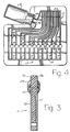
- the disposable, multi-well, self-pipetting device of the present invention consists of a frame 11 made from a solid block of acrylic plastic or other suitable material.
- a filling manifold system 13 is formed in the surface of the frame by machining of grooves or other suitable method.
- the filling manifold system 13 includes a filling manifold 15 and a series of filling passageways 17 leading from the filling manifold 15 to each of a series of test wells 19.
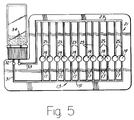
- a venting manifold system 21 is formed in a similar fashion on the back side of the frame 11.
- the venting manifold system 21 includes a venting manifold 23 and a series of venting passageways 25 leading from the test wells 19 to the venting manifold 23.
- the filling manifold system 15 and the venting manifold system 21 are machined or otherwise formed on opposite sides of the frame 11.
- the test wells 19 are drilled or otherwise formed through the frame.
- a docking port 27 is formed on a peripheral surface, which can be an edge or planer surface, of the frame 11.
- the docking port 27 is adapted to receive a specimen reservoir or vial 29.
- the docking port 27 comprises a screw type cap which is affixed to the periphery of the frame 11.
- the screw cap receives the threads of a specimen vial 29 when it is desired to use the cartridge of the invention.
- a filling channel 31 is drilled or otherwise formed through the frame 11 and leads from a filling port 32 to form a fluid communication channel with the filling manifold system 13.
- a venting channel 33 is also drilled or otherwise formed through the frame 11 and leads from a venting port 34 to form a fluid communication channel with the venting manifold system 23.
- a reservoir 29, such as a vial, containing a sample of inoculated serum or other fluid specimen is screwed into a mating relationship with the docking port 27.
- the device is oriented in a vertical position and is placed in a rack for incubation of the inoculum .
- the test wells 19 are provided with a variety of dry chemicals such as freeze dried carbohydrate media, prior to sealing the test wells, which react with various microorganisms or other analytes of interest.
- a color change in a series of test wells indicates the reactants which react with the microorganism to provide identification of the microorganism.
- the junction of the venting passageways 25 with the venting manifold 23 of the venting system 23 is always at an elevation higher than the surface of the fluid in the reservoir 29 when the device is located in its operational position.
- the entire venting manifold is at an elevation higher than the surface of the fluid, although sections of the venting manifold 23 between the junction of the venting passageways 25 and the venting manifold could be lower than the surface of the fluid.
- the venting port 34 of the venting manifold system 21 is also positioned higher than the surface level of the liquid specimen in the vial when the device is inverted into operating position.
- a vent extension tube 35 may be provided to move the venting port 34 above the liquid level, although this is optional, since air which is displaced by the advance of fluid into the test wells would bubble thru the fluid in the reservoir. Air in the system vents through the venting manifold 23, and through venting channel 33 into the serum vial.
- the intake manifold 15 can be positioned at any point lower than the filling port 32.
- the positioning of the vent manifold 23 above the surface of fluid in the reservoir assures that all of the test wells will fill and not be cut off by fluid from another test well.
- the venting manifold 23 of the venting manifold system 21 is positioned higher than the surface level of the fluid in the reservoir when the device is located into operating position. Such positioning of the venting manifold 23 assures that all of the test wells will fill and not be cutoff by fluid from another test well.
- Flow of the fluid is from the reservoir into the filling manifold system 13, into the test wells 19, out of the test wells 19 and into the venting manifold system 23 and out of the venting manifold system 15 through venting channel 33 and back into the serum vial.
- the disposable, self-pipetting, multi-well device of the present invention provides a disposable cartridge for the delivery of small amounts (about 100 microliters) of fluid to a series of wells from one source. Gravity is used to move the fluid without need for the provision of a pressure source or a vacuum source. As shown in Figure 1, when located in operational position, the venting port 34 of the venting manifold system 23 at the end of the venting channel 33 is higher than the inlet at the end of the filling channel 31 which connects with the filling manifold system 13.
- the intake manifold and the venting manifold may be located on the same side of the frame 11. In each of these embodiments, the intake manifold 15 is located below the test wells and the filling port.
- the configuration of the disposable, multi-well, self-pipetting device of the present invention is adapted to many variations without departing from the scope of the invention. It should be understood that other variations are also included within the scope of the invention.
- the devices shown in drawings are depicted with planar frames, the frame could be made curvilinear or cylindrical. Also, the frame could be folded on either a vertical or horizontal axis. Curving or folding the frame would provide a device which would be capable of self alignment into a standup operational position.
- the frame of the disposable device of the present invention can be made by lamination of several layers.
- a reagent reservoir 41 is provided within the frame for dispensing a secondary reagent to preselected test wells for observation of the reaction of the reagent with the specimen.
- a reservoir within the frame could also be the primary reservoir obviating this need for docking port 27 reservoir 29.
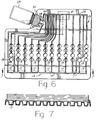
- the routing circuit for distribution of the specimen through the intake manifold system 13 and the venting manifold system 23 with routing of the reagent in the reagent well 19 is shown in Figures 4-9. Any desired circuit of movement of the specimen through a series of test wells can be provided by altering the laminar construction shown in Figures 4-9.
- Laminations can be added to allow for utilization of specified wells. Selected wells can remain visible and selected wells can be filled. Time regulated fluid reaction may be implemented using one of several arrangements; three possibilities include ladder channel arrangement, liposome technology, or the use of dissolvable crystals. Originally filled wells can be allowed to move to adjacent wells by venting thru a pierced vent hole or by valve placement. Vent holes may be resealed using removable tape or other suitable material.
- the laminar layers shown in Figure 7 may be made with sheet material or may be molded to result in fewer layers with the same result.
- the device in Figure 9 is prepared by machining or otherwise forming the filling manifold 15, the filling passageways 17, the filling channel 31, the venting manifold 23, the venting passageways 25, the venting channel 33 and primary test wells 19 in a suitable frame 11.
- secondary test wells 20 and a tertiary test well 22 are formed in the frame 11.
- Auxiliary venting passageways 24 lead from test wells 20 to a terminus vent hole 28 near the top of the frame.
- a venting passageway 24a leads from test well 22 to a terminus vent hole 28a.
- the fluid specimen in the vial 29 first fills test wells 19 which are in return communication with the vial through the venting manifold system 21.
- Test wells 20 and 22 will not fill because of back pressure produced by blocking of auxiliary venting passageways 24 and 24a at the vent holes 28 and 28a.
- the venting passageways 24 become open to ambient pressure and the fluid specimen will proceed from test wells 19 to test wells 20.
- the venting passageway 24a becomes open to ambient pressure and the fluid specimen will proceed from test well 20 to test well 22.
- many combinations of one, two, three or more test well configurations can be devised for a single testing device depending on the chemical reactions or manipulations required for the fluid specimen.
Claims (9)
- Un dispositif de prélèvement automatique à la pipette, à logements multiples, pour analyses chimiques, immuno-chimiques et microbiologiques, ledit dispositif comprenant:
un châssis comprenant un corps et un ensemble périphérique orientés en position de travail (11);
une pluralité de logements d'analyse disposés dans ledit corps (19);
un collecteur de remplissage (13) monté dans ledit châssis, ledit collecteur de remplissage étant en communication fluidique avec chacun des logements de ladite pluralité de logements d'analyse;
un collecteur de purge (23) monté en position dans ledit châssis, au-dessus du collecteur de remplissage et au-dessus de la pluralité de logements d'analyse, ledit collecteur de purge étant en communication fluidique avec chacun des logements de ladite pluralité de logements d'analyse; et
une tubulure de chargement (27) pour recevoir un récipient contenant un échantillon de fluide, ladite tubulure de chargement étant située sur la périphérie dudit châssis, ladite tubulure de chargement étant en communication fluidique avec ledit collecteur de remplissage et avec ledit collecteur de purge. - Un dispositif selon la revendication 1, dans lequel ladite tubulure de chargement est située dans une position intermédiaire entre ledit collecteur de remplissage et ledit collecteur de purge.
- Un dispositif selon la revendication 1, dans lequel un réservoir contenant un échantillon de fluide est adapté sur ladite tubulure de chargement.
- Un dispositif selon la revendication 3, dans lequel l'échantillon de fluide comprend un niveau supérieur et ledit collecteur de purge est placé dans une position située au-dessus du niveau supérieur dudit échantillon de fluide lorsque ledit dispositif est placé dans ladite position de travail.
- Un dispositif selon la revendication 1, dans lequel des réactifs sont placés dans lesdits logements d'analyse.
- Un dispositif selon la revendication 1, dans lequel des groupes de logements d'analyse prédéterminés sont raccordés séquentiellement par des passages de raccordement.
- Un dispositif selon la revendication 6, dans lequel un passage de purge auxiliaire est en communication fluidique avec au moins l'un des logements de ladite pluralité de logements d'analyse de l'un desdits groupes, ledit passage auxiliaire étant isolé dudit collecteur de purge et ledit passage auxiliaire conduisant à un orifice de purge et à des moyens pour exposer ledit orifice de purge à la pression ambiante ou pour le mettre en communication fluidique avec ledit collecteur de purge.
- Un dispositif selon la revendication 1, plié suivant un axe horizontal ou vertical.
- Un dispositif selon la revendication 1, agencé selon une forme curviligne.
Priority Applications (1)
| Application Number | Priority Date | Filing Date | Title |
|---|---|---|---|
| AT88103376T ATE89601T1 (de) | 1987-03-17 | 1988-03-04 | Einweg-vorrichtung zur verwendung bei chemischen, immunochemischen und mikrobiologischen analysen. |
Applications Claiming Priority (2)
| Application Number | Priority Date | Filing Date | Title |
|---|---|---|---|
| US07/027,280 US4806316A (en) | 1987-03-17 | 1987-03-17 | Disposable device for use in chemical, immunochemical and microorganism analysis |
| US27280 | 1987-03-17 |
Publications (3)
| Publication Number | Publication Date |
|---|---|
| EP0282840A2 EP0282840A2 (fr) | 1988-09-21 |
| EP0282840A3 EP0282840A3 (en) | 1990-03-14 |
| EP0282840B1 true EP0282840B1 (fr) | 1993-05-19 |
Family
ID=21836742
Family Applications (1)
| Application Number | Title | Priority Date | Filing Date |
|---|---|---|---|
| EP88103376A Expired - Lifetime EP0282840B1 (fr) | 1987-03-17 | 1988-03-04 | Dispositif à usage unique à utiliser pour des analyses chimiques, immunochimiques et microbiologiques |
Country Status (10)
| Country | Link |
|---|---|
| US (1) | US4806316A (fr) |
| EP (1) | EP0282840B1 (fr) |
| JP (1) | JPS63258650A (fr) |
| AT (1) | ATE89601T1 (fr) |
| AU (1) | AU604857B2 (fr) |
| CA (1) | CA1308635C (fr) |
| DE (1) | DE3881085T2 (fr) |
| DK (1) | DK168578B1 (fr) |
| ES (1) | ES2040283T3 (fr) |
| FI (1) | FI93147C (fr) |
Families Citing this family (90)
| Publication number | Priority date | Publication date | Assignee | Title |
|---|---|---|---|---|
| US4918025A (en) * | 1987-03-03 | 1990-04-17 | Pb Diagnostic Systems, Inc. | Self contained immunoassay element |
| US5472671A (en) * | 1989-04-26 | 1995-12-05 | Nilsson; Sven-Erik | Cuvette |
| US5286454A (en) * | 1989-04-26 | 1994-02-15 | Nilsson Sven Erik | Cuvette |
| SE465742B (sv) * | 1989-04-26 | 1991-10-21 | Migrata Uk Ltd | Kyvett foer upptagning foer minst ett fluidum |
| US5225163A (en) * | 1989-08-18 | 1993-07-06 | Angenics, Inc. | Reaction apparatus employing gravitational flow |
| CA2084342A1 (fr) * | 1990-06-15 | 1991-12-16 | Rich T. Smethers | Appareil autonome d'analyse |
| US5063090A (en) * | 1990-06-29 | 1991-11-05 | Difco Laboratories | Lecithin as a wettability enhancing coating for plastic |
| US5182082A (en) * | 1991-01-23 | 1993-01-26 | Becton, Dickinson And Company | Multiple aliquot device for distributing a liquid solution into a well |
| US5145646A (en) * | 1991-06-03 | 1992-09-08 | Abbott Laboratories | Reagent bottle and cap |
| US5254315A (en) * | 1991-07-26 | 1993-10-19 | E. I. Du Pont De Nemours And Company | Carrier device |
| DE69329424T2 (de) * | 1992-11-06 | 2001-04-19 | Biolog Inc | Testvorrichtung für flüssig- und suspensionsproben |
| US5609828A (en) * | 1995-05-31 | 1997-03-11 | bio M erieux Vitek, Inc. | Sample card |
| US5759847A (en) * | 1995-07-14 | 1998-06-02 | Difco Laboratories | System and apparatus for automatically transferring media |
| US5709840A (en) * | 1996-01-11 | 1998-01-20 | Tecan Us., Inc. | Reactor flask |
| AU686503B2 (en) * | 1996-01-17 | 1998-02-05 | Biomerieux Vitek, Inc. | Test sample card |
| EP1174188B1 (fr) * | 1996-01-17 | 2003-01-15 | bioMerieux Vitek, Inc. | Carte test pour analyses |
| IL118155A (en) | 1996-05-06 | 2000-02-29 | Combact Diagnostic Systems Ltd | Method and device for handling specimens |
| US6232124B1 (en) | 1996-05-06 | 2001-05-15 | Verification Technologies, Inc. | Automated fingerprint methods and chemistry for product authentication and monitoring |
| WO1998000705A1 (fr) * | 1996-06-28 | 1998-01-08 | Caliper Technologies Corporation | Electropipette et systeme de compensation pour polarisation electrophoretique |
| JP4000605B2 (ja) | 1996-07-24 | 2007-10-31 | 株式会社日立製作所 | Dna試料調整装置及びこれを用いる電気泳動分析装置 |
| US6391578B2 (en) | 1997-04-09 | 2002-05-21 | 3M Innovative Properties Company | Method and devices for partitioning biological sample liquids into microvolumes |
| US6696286B1 (en) | 1997-04-09 | 2004-02-24 | 3M Innovative Properties Company | Method and devices for detecting and enumerating microorganisms |
| FR2762092B1 (fr) | 1997-04-15 | 1999-05-28 | Bio Merieux | Procede et dispositif de remplissage avec un milieu liquide d'une carte d'analyse |
| US5922593A (en) * | 1997-05-23 | 1999-07-13 | Becton, Dickinson And Company | Microbiological test panel and method therefor |
| US6426230B1 (en) | 1997-08-01 | 2002-07-30 | Qualigen, Inc. | Disposable diagnostic device and method |
| US5804437A (en) * | 1997-08-19 | 1998-09-08 | Biomerieux Vitek, Inc. | Locking structure for securing a fluid transfer tube |
| DE69930726T2 (de) * | 1998-01-12 | 2007-01-25 | Massachusetts Institute Of Technology, Cambridge | Verfahren und vorrichtung zur mikrotestdurchführung |
| IL138286A (en) * | 1998-03-11 | 2004-02-19 | Steag Micro Parts Gmbh | Sample support |
| GB9808836D0 (en) | 1998-04-27 | 1998-06-24 | Amersham Pharm Biotech Uk Ltd | Microfabricated apparatus for cell based assays |
| GB9809943D0 (en) | 1998-05-08 | 1998-07-08 | Amersham Pharm Biotech Ab | Microfluidic device |
| FR2782729B1 (fr) | 1998-09-01 | 2002-10-25 | Bio Merieux | Carte de denombrement et de caracterisation de micro-organismes |
| US6759013B2 (en) * | 1998-09-17 | 2004-07-06 | Agilent Technologies, Inc. | Modular apparatus for chemical microanalysis |
| US6490030B1 (en) | 1999-01-18 | 2002-12-03 | Verification Technologies, Inc. | Portable product authentication device |
| US6174699B1 (en) | 1999-03-09 | 2001-01-16 | 3M Innovative Properties Company | Disc assay device with inoculation pad and methods of use |
| FR2790684B1 (fr) | 1999-03-09 | 2001-05-11 | Biomerieux Sa | Appareil permettant en son sein le transfert de liquides par capillarite |
| FR2790683B1 (fr) * | 1999-03-09 | 2001-05-11 | Biomerieux Sa | Dispositif et procede de positionnement d'un liquide |
| US6818185B1 (en) | 1999-05-28 | 2004-11-16 | Cepheid | Cartridge for conducting a chemical reaction |
| US7079230B1 (en) | 1999-07-16 | 2006-07-18 | Sun Chemical B.V. | Portable authentication device and method of authenticating products or product packaging |
| US6512580B1 (en) | 1999-10-27 | 2003-01-28 | Verification Technologies, Inc. | Method and apparatus for portable product authentication |
| US20030112423A1 (en) * | 2000-04-24 | 2003-06-19 | Rakesh Vig | On-line verification of an authentication mark applied to products or product packaging |
| US20040000787A1 (en) * | 2000-04-24 | 2004-01-01 | Rakesh Vig | Authentication mark for a product or product package |
| US6627159B1 (en) * | 2000-06-28 | 2003-09-30 | 3M Innovative Properties Company | Centrifugal filling of sample processing devices |
| WO2002002301A1 (fr) | 2000-06-30 | 2002-01-10 | Verification Technologies Inc. | Support optique protege et procede de fabrication |
| US7124944B2 (en) * | 2000-06-30 | 2006-10-24 | Verification Technologies, Inc. | Product packaging including digital data |
| US7486790B1 (en) | 2000-06-30 | 2009-02-03 | Verification Technologies, Inc. | Method and apparatus for controlling access to storage media |
| US6638593B2 (en) | 2000-06-30 | 2003-10-28 | Verification Technologies, Inc. | Copy-protected optical media and method of manufacture thereof |
| US7660415B2 (en) * | 2000-08-03 | 2010-02-09 | Selinfreund Richard H | Method and apparatus for controlling access to storage media |
| US8097471B2 (en) * | 2000-11-10 | 2012-01-17 | 3M Innovative Properties Company | Sample processing devices |
| IL141111A0 (en) * | 2001-01-25 | 2002-02-10 | Biopreventive Ltd | Reaction vessel and system incorporating same |
| CA2441206A1 (fr) | 2001-03-19 | 2002-09-26 | Gyros Ab | Caracterisation de variables de reaction |
| US20020187564A1 (en) * | 2001-06-08 | 2002-12-12 | Caliper Technologies Corp. | Microfluidic library analysis |
| EP1952886B1 (fr) * | 2001-07-16 | 2021-06-23 | BioFire Defense, LLC | Système de cycle thermique et procédé d'utilisation |
| US20050084645A1 (en) * | 2002-02-07 | 2005-04-21 | Selinfreund Richard H. | Method and system for optical disc copy-protection |
| EP1493024A1 (fr) | 2002-04-09 | 2005-01-05 | Humboldt-Universität zu Berlin | Collecteur automatique d'echantillons |
| US20060084183A1 (en) * | 2002-05-24 | 2006-04-20 | F. Sperling Aps | Method for testing the interaction between at least one liquid sample and respective solid sample |
| US20040023397A1 (en) * | 2002-08-05 | 2004-02-05 | Rakesh Vig | Tamper-resistant authentication mark for use in product or product packaging authentication |
| MXPA05003218A (es) * | 2002-09-26 | 2005-09-12 | Verification Technologies Inc | Autentificacion de items que utilizan materiales de cambio transitorio de estado optico. |
| EP1419818B1 (fr) * | 2002-11-14 | 2013-10-30 | Boehringer Ingelheim microParts GmbH | Dispositif pour le transport de liquide avec des forces capillaires |
| US7507376B2 (en) * | 2002-12-19 | 2009-03-24 | 3M Innovative Properties Company | Integrated sample processing devices |
| US20040129676A1 (en) * | 2003-01-07 | 2004-07-08 | Tan Roy H. | Apparatus for transfer of an array of liquids and methods for manufacturing same |
| US20060203700A1 (en) * | 2003-02-06 | 2006-09-14 | Verification Technologies, Inc. | Method and system for optical disk copy-protection |
| JP5118849B2 (ja) * | 2003-03-17 | 2013-01-16 | チャールズ リバー ラボラトリーズ, インコーポレイテッド | 微生物夾雑物の検出のための方法および組成物 |
| US20050047967A1 (en) * | 2003-09-03 | 2005-03-03 | Industrial Technology Research Institute | Microfluidic component providing multi-directional fluid movement |
| WO2005029041A2 (fr) * | 2003-09-19 | 2005-03-31 | Applera Corporation | Procedes et appareil de detection de sequence haute densite |
| US7718133B2 (en) * | 2003-10-09 | 2010-05-18 | 3M Innovative Properties Company | Multilayer processing devices and methods |
| US7431890B2 (en) * | 2003-11-17 | 2008-10-07 | Sakura Finetek U.S.A., Inc. | Fluid system coupler |
| DE10354806A1 (de) * | 2003-11-21 | 2005-06-02 | Boehringer Ingelheim Microparts Gmbh | Probenträger |
| US7932090B2 (en) * | 2004-08-05 | 2011-04-26 | 3M Innovative Properties Company | Sample processing device positioning apparatus and methods |
| DE102004046618A1 (de) * | 2004-09-25 | 2006-03-30 | Robert Bosch Gmbh | Schaltungsanordnung zum Analog/Digital-Wandeln |
| US7264206B2 (en) * | 2004-09-30 | 2007-09-04 | The Boeing Company | Leading edge flap apparatuses and associated methods |
| JP2008522640A (ja) | 2004-12-02 | 2008-07-03 | チャールズ リバー ラボラトリーズ, インコーポレイテッド | グラム陽性菌夾雑物の検出および/または定量化のための方法ならびに組成物 |
| EP1836492B1 (fr) | 2005-01-13 | 2008-12-31 | Charles River Laboratories, Inc. | Procede de classification d'un micro-organisme dans un echantillon biologique |
| EP1707267A1 (fr) * | 2005-03-30 | 2006-10-04 | F. Hoffman-la Roche AG | dispositif avec port refermable |
| US20080206795A1 (en) * | 2005-04-04 | 2008-08-28 | Ernst Heinen | Novel Supports, in Particular for Immunodetection of Molecules of Interest |
| JP4933301B2 (ja) * | 2007-02-22 | 2012-05-16 | キヤノン株式会社 | 検体処理装置 |
| CN101970111B (zh) | 2007-06-21 | 2013-09-11 | 简·探针公司 | 用于执行处理的仪器和容器 |
| AU2008275188B2 (en) | 2007-07-09 | 2012-01-19 | 3M Innovative Properties Company | Modular system and method for detecting microorganisms |
| DE102007036611B4 (de) | 2007-08-02 | 2015-10-08 | Deutsche Diabetes-Forschungsgesellschaft E.V. | Verfahren und Vorrichtung zur Kultivierung lebender Zellen |
| JP4411661B2 (ja) * | 2007-10-26 | 2010-02-10 | セイコーエプソン株式会社 | 生体物質検出方法 |
| US8001855B2 (en) * | 2008-01-14 | 2011-08-23 | Medi Medical Engineering Corp. | Fluid transferring apparatus |
| US20090286692A1 (en) * | 2008-04-15 | 2009-11-19 | Wainwright Norman R | Cartridge and Method for Sample Analysis |
| EP2442092A3 (fr) * | 2010-08-23 | 2013-05-29 | HORIBA, Ltd. | Cartouche d'analyse cellulaire avec un canal de mesure d'impédance |
| CN103154744B (zh) | 2010-10-08 | 2015-05-20 | 生物梅里埃有限公司 | 改进的样品测试卡 |
| CA2811951C (fr) | 2010-11-23 | 2018-12-11 | Biomerieux, Inc. | Cartes de test d'echantillon ameliorees |
| EP3151965B1 (fr) | 2014-06-04 | 2021-02-24 | Edan Instruments, Inc. | Prélèvement d'échantillons et dispositifs d'analyse |
| US9494510B2 (en) | 2015-02-06 | 2016-11-15 | John L. Sternick | Cuvette system |
| US9279761B1 (en) | 2015-02-06 | 2016-03-08 | John L. Sternick | Cuvette system |
| CN111495447B (zh) | 2015-05-01 | 2022-08-26 | 雅培制药有限公司 | 用于去除容器的液体内含物的设备 |
| US20160354781A1 (en) * | 2015-06-08 | 2016-12-08 | National Taiwan University | Microfluidic plate for sample processing |
| BR102017015998A2 (pt) * | 2017-07-26 | 2019-03-26 | Sociedade Beneficente Israelita Brasileira Hospital Albert Einstein | Película seladora e método de pipetagem utilizando uma película seladora |
Family Cites Families (7)
| Publication number | Priority date | Publication date | Assignee | Title |
|---|---|---|---|---|
| FR1598197A (fr) * | 1968-11-19 | 1970-07-06 | ||
| US3957583A (en) * | 1974-12-02 | 1976-05-18 | Mcdonnell Douglas Corporation | Apparatus and process for determining the susceptibility of microorganisms to antibiotics |
| US4018652A (en) * | 1976-01-09 | 1977-04-19 | Mcdonnell Douglas Corporation | Process and apparatus for ascertaining the concentration of microorganism in a water specimen |
| US4207394A (en) * | 1976-01-28 | 1980-06-10 | Mcdonnell Douglas Corporation | Process and apparatus for analyzing specimens for the presence of microorganisms therein |
| US4116775A (en) * | 1976-05-03 | 1978-09-26 | Mcdonnell Douglas Corporation | Machine and process for reading cards containing medical specimens |
| US4330627A (en) * | 1979-02-09 | 1982-05-18 | Ryder International Corporation | Testing tray |
| US4318994A (en) * | 1979-08-30 | 1982-03-09 | Mcdonnell Douglas Corporation | Enterobacteriaceae species biochemical test card |
-
1987
- 1987-03-17 US US07/027,280 patent/US4806316A/en not_active Expired - Fee Related
-
1988
- 1988-03-02 CA CA000560282A patent/CA1308635C/fr not_active Expired - Fee Related
- 1988-03-04 AT AT88103376T patent/ATE89601T1/de not_active IP Right Cessation
- 1988-03-04 ES ES198888103376T patent/ES2040283T3/es not_active Expired - Lifetime
- 1988-03-04 EP EP88103376A patent/EP0282840B1/fr not_active Expired - Lifetime
- 1988-03-04 DE DE8888103376T patent/DE3881085T2/de not_active Expired - Fee Related
- 1988-03-11 AU AU13005/88A patent/AU604857B2/en not_active Ceased
- 1988-03-16 FI FI881257A patent/FI93147C/fi not_active IP Right Cessation
- 1988-03-17 DK DK146888A patent/DK168578B1/da not_active IP Right Cessation
- 1988-03-17 JP JP63064671A patent/JPS63258650A/ja active Granted
Also Published As
| Publication number | Publication date |
|---|---|
| FI881257A (fi) | 1988-09-18 |
| DK146888A (da) | 1988-09-18 |
| US4806316A (en) | 1989-02-21 |
| ATE89601T1 (de) | 1993-06-15 |
| FI881257A0 (fi) | 1988-03-16 |
| ES2040283T3 (es) | 1993-10-16 |
| FI93147C (fi) | 1995-02-27 |
| JPS63258650A (ja) | 1988-10-26 |
| DE3881085D1 (de) | 1993-06-24 |
| AU604857B2 (en) | 1991-01-03 |
| EP0282840A3 (en) | 1990-03-14 |
| DK146888D0 (da) | 1988-03-17 |
| EP0282840A2 (fr) | 1988-09-21 |
| DK168578B1 (da) | 1994-04-25 |
| DE3881085T2 (de) | 1993-09-02 |
| AU1300588A (en) | 1988-09-15 |
| CA1308635C (fr) | 1992-10-13 |
| FI93147B (fi) | 1994-11-15 |
| JPH0426902B2 (fr) | 1992-05-08 |
Similar Documents
| Publication | Publication Date | Title |
|---|---|---|
| EP0282840B1 (fr) | Dispositif à usage unique à utiliser pour des analyses chimiques, immunochimiques et microbiologiques | |
| EP0180064B1 (fr) | Dispositif de manipulation de liquides | |
| US6818435B2 (en) | Microfluidics devices and methods for performing cell based assays | |
| US7125711B2 (en) | Method and apparatus for splitting of specimens into multiple channels of a microfluidic device | |
| US4077845A (en) | Disposable inoculation device and process of using same | |
| EP0281201B1 (fr) | Dispositif d'essai immunologique intégré | |
| EP1364710B1 (fr) | Plaque de stockage d'échantillon avec système de distribution d'aliquotes | |
| JP4350897B2 (ja) | 試料担体 | |
| US5147606A (en) | Self-metering fluid analysis device | |
| EP0496200B1 (fr) | Dispositif pour plusieurs échantillons | |
| EP1409989B1 (fr) | Procedure pour separer les composantes d'un melange | |
| CA1257523A (fr) | Procede de transport de liquide | |
| EP1441229B1 (fr) | Méthode et système micro-fluidique automatisé pour la détection de protéines dans des échantillons biologiques | |
| US20010001644A1 (en) | Plate alignment and sample transfer indicia for a multiwell multiplate stack and method for processing biological/chemical samples using the same | |
| US6942836B2 (en) | System for filling substrate chambers with liquid | |
| US6015531A (en) | Single-use analysis card comprising a liquid flow duct | |
| US20210016274A1 (en) | Microfluidic chip | |
| CN111774111B (zh) | 一种用于检测糖化血红蛋白的微流控芯片及其检测方法 | |
| JP2004519235A (ja) | 生物学的検査アレイにおける液体の流れ及び制御 | |
| CN208776710U (zh) | 加载装置及基因测序系统 |
Legal Events
| Date | Code | Title | Description |
|---|---|---|---|
| PUAI | Public reference made under article 153(3) epc to a published international application that has entered the european phase |
Free format text: ORIGINAL CODE: 0009012 |
|
| AK | Designated contracting states |
Kind code of ref document: A2 Designated state(s): AT BE CH DE ES FR GB GR IT LI NL SE |
|
| PUAL | Search report despatched |
Free format text: ORIGINAL CODE: 0009013 |
|
| AK | Designated contracting states |
Kind code of ref document: A3 Designated state(s): AT BE CH DE ES FR GB GR IT LI NL SE |
|
| 17P | Request for examination filed |
Effective date: 19900905 |
|
| 17Q | First examination report despatched |
Effective date: 19920512 |
|
| GRAA | (expected) grant |
Free format text: ORIGINAL CODE: 0009210 |
|
| AK | Designated contracting states |
Kind code of ref document: B1 Designated state(s): AT BE CH DE ES FR GB GR IT LI NL SE |
|
| REF | Corresponds to: |
Ref document number: 89601 Country of ref document: AT Date of ref document: 19930615 Kind code of ref document: T |
|
| ET | Fr: translation filed | ||
| ITF | It: translation for a ep patent filed |
Owner name: ING. C. GREGORJ S.P.A. |
|
| REF | Corresponds to: |
Ref document number: 3881085 Country of ref document: DE Date of ref document: 19930624 |
|
| ET | Fr: translation filed |
Free format text: BO 21/93 PAGE 187: ANNULATION |
|
| ET | Fr: translation filed | ||
| REG | Reference to a national code |
Ref country code: GR Ref legal event code: FG4A Free format text: 3007923 |
|
| REG | Reference to a national code |
Ref country code: ES Ref legal event code: FG2A Ref document number: 2040283 Country of ref document: ES Kind code of ref document: T3 |
|
| PLBE | No opposition filed within time limit |
Free format text: ORIGINAL CODE: 0009261 |
|
| STAA | Information on the status of an ep patent application or granted ep patent |
Free format text: STATUS: NO OPPOSITION FILED WITHIN TIME LIMIT |
|
| 26N | No opposition filed | ||
| EAL | Se: european patent in force in sweden |
Ref document number: 88103376.5 |
|
| PGFP | Annual fee paid to national office [announced via postgrant information from national office to epo] |
Ref country code: GB Payment date: 19980223 Year of fee payment: 11 |
|
| PGFP | Annual fee paid to national office [announced via postgrant information from national office to epo] |
Ref country code: FR Payment date: 19980310 Year of fee payment: 11 |
|
| PGFP | Annual fee paid to national office [announced via postgrant information from national office to epo] |
Ref country code: CH Payment date: 19980311 Year of fee payment: 11 Ref country code: AT Payment date: 19980311 Year of fee payment: 11 |
|
| PGFP | Annual fee paid to national office [announced via postgrant information from national office to epo] |
Ref country code: DE Payment date: 19980313 Year of fee payment: 11 |
|
| PGFP | Annual fee paid to national office [announced via postgrant information from national office to epo] |
Ref country code: SE Payment date: 19980317 Year of fee payment: 11 Ref country code: GR Payment date: 19980317 Year of fee payment: 11 |
|
| PGFP | Annual fee paid to national office [announced via postgrant information from national office to epo] |
Ref country code: NL Payment date: 19980326 Year of fee payment: 11 |
|
| PGFP | Annual fee paid to national office [announced via postgrant information from national office to epo] |
Ref country code: ES Payment date: 19980327 Year of fee payment: 11 |
|
| PGFP | Annual fee paid to national office [announced via postgrant information from national office to epo] |
Ref country code: BE Payment date: 19980518 Year of fee payment: 11 |
|
| PG25 | Lapsed in a contracting state [announced via postgrant information from national office to epo] |
Ref country code: GB Free format text: LAPSE BECAUSE OF NON-PAYMENT OF DUE FEES Effective date: 19990304 Ref country code: AT Free format text: LAPSE BECAUSE OF NON-PAYMENT OF DUE FEES Effective date: 19990304 |
|
| PG25 | Lapsed in a contracting state [announced via postgrant information from national office to epo] |
Ref country code: SE Free format text: LAPSE BECAUSE OF NON-PAYMENT OF DUE FEES Effective date: 19990305 Ref country code: ES Free format text: LAPSE BECAUSE OF EXPIRATION OF PROTECTION Effective date: 19990305 |
|
| PG25 | Lapsed in a contracting state [announced via postgrant information from national office to epo] |
Ref country code: LI Free format text: LAPSE BECAUSE OF NON-PAYMENT OF DUE FEES Effective date: 19990331 Ref country code: GR Free format text: LAPSE BECAUSE OF NON-PAYMENT OF DUE FEES Effective date: 19990331 Ref country code: CH Free format text: LAPSE BECAUSE OF NON-PAYMENT OF DUE FEES Effective date: 19990331 Ref country code: BE Free format text: LAPSE BECAUSE OF NON-PAYMENT OF DUE FEES Effective date: 19990331 |
|
| BERE | Be: lapsed |
Owner name: BECTON DICKINSON AND CY Effective date: 19990331 |
|
| PG25 | Lapsed in a contracting state [announced via postgrant information from national office to epo] |
Ref country code: NL Free format text: LAPSE BECAUSE OF NON-PAYMENT OF DUE FEES Effective date: 19991001 |
|
| GBPC | Gb: european patent ceased through non-payment of renewal fee |
Effective date: 19990304 |
|
| EUG | Se: european patent has lapsed |
Ref document number: 88103376.5 |
|
| REG | Reference to a national code |
Ref country code: CH Ref legal event code: PL |
|
| PG25 | Lapsed in a contracting state [announced via postgrant information from national office to epo] |
Ref country code: FR Free format text: LAPSE BECAUSE OF NON-PAYMENT OF DUE FEES Effective date: 19991130 |
|
| NLV4 | Nl: lapsed or anulled due to non-payment of the annual fee |
Effective date: 19991001 |
|
| EUG | Se: european patent has lapsed |
Ref document number: 88103376.5 |
|
| REG | Reference to a national code |
Ref country code: FR Ref legal event code: ST |
|
| PG25 | Lapsed in a contracting state [announced via postgrant information from national office to epo] |
Ref country code: DE Free format text: LAPSE BECAUSE OF NON-PAYMENT OF DUE FEES Effective date: 20000101 |
|
| REG | Reference to a national code |
Ref country code: ES Ref legal event code: FD2A Effective date: 20010601 |
|
| PG25 | Lapsed in a contracting state [announced via postgrant information from national office to epo] |
Ref country code: IT Free format text: LAPSE BECAUSE OF NON-PAYMENT OF DUE FEES;WARNING: LAPSES OF ITALIAN PATENTS WITH EFFECTIVE DATE BEFORE 2007 MAY HAVE OCCURRED AT ANY TIME BEFORE 2007. THE CORRECT EFFECTIVE DATE MAY BE DIFFERENT FROM THE ONE RECORDED. Effective date: 20050304 |