EP1441229B1 - Méthode et système micro-fluidique automatisé pour la détection de protéines dans des échantillons biologiques - Google Patents
Méthode et système micro-fluidique automatisé pour la détection de protéines dans des échantillons biologiques Download PDFInfo
- Publication number
- EP1441229B1 EP1441229B1 EP04001087A EP04001087A EP1441229B1 EP 1441229 B1 EP1441229 B1 EP 1441229B1 EP 04001087 A EP04001087 A EP 04001087A EP 04001087 A EP04001087 A EP 04001087A EP 1441229 B1 EP1441229 B1 EP 1441229B1
- Authority
- EP
- European Patent Office
- Prior art keywords
- dye
- sample
- control
- compressed
- buffer
- Prior art date
- Legal status (The legal status is an assumption and is not a legal conclusion. Google has not performed a legal analysis and makes no representation as to the accuracy of the status listed.)
- Expired - Fee Related
Links
Images


Classifications
-
- G—PHYSICS
- G01—MEASURING; TESTING
- G01N—INVESTIGATING OR ANALYSING MATERIALS BY DETERMINING THEIR CHEMICAL OR PHYSICAL PROPERTIES
- G01N35/00—Automatic analysis not limited to methods or materials provided for in any single one of groups G01N1/00 - G01N33/00; Handling materials therefor
- G01N35/02—Automatic analysis not limited to methods or materials provided for in any single one of groups G01N1/00 - G01N33/00; Handling materials therefor using a plurality of sample containers moved by a conveyor system past one or more treatment or analysis stations
-
- B—PERFORMING OPERATIONS; TRANSPORTING
- B01—PHYSICAL OR CHEMICAL PROCESSES OR APPARATUS IN GENERAL
- B01L—CHEMICAL OR PHYSICAL LABORATORY APPARATUS FOR GENERAL USE
- B01L3/00—Containers or dishes for laboratory use, e.g. laboratory glassware; Droppers
- B01L3/50—Containers for the purpose of retaining a material to be analysed, e.g. test tubes
- B01L3/502—Containers for the purpose of retaining a material to be analysed, e.g. test tubes with fluid transport, e.g. in multi-compartment structures
- B01L3/5027—Containers for the purpose of retaining a material to be analysed, e.g. test tubes with fluid transport, e.g. in multi-compartment structures by integrated microfluidic structures, i.e. dimensions of channels and chambers are such that surface tension forces are important, e.g. lab-on-a-chip
- B01L3/502723—Containers for the purpose of retaining a material to be analysed, e.g. test tubes with fluid transport, e.g. in multi-compartment structures by integrated microfluidic structures, i.e. dimensions of channels and chambers are such that surface tension forces are important, e.g. lab-on-a-chip characterised by venting arrangements
-
- B—PERFORMING OPERATIONS; TRANSPORTING
- B01—PHYSICAL OR CHEMICAL PROCESSES OR APPARATUS IN GENERAL
- B01L—CHEMICAL OR PHYSICAL LABORATORY APPARATUS FOR GENERAL USE
- B01L2200/00—Solutions for specific problems relating to chemical or physical laboratory apparatus
- B01L2200/10—Integrating sample preparation and analysis in single entity, e.g. lab-on-a-chip concept
-
- B—PERFORMING OPERATIONS; TRANSPORTING
- B01—PHYSICAL OR CHEMICAL PROCESSES OR APPARATUS IN GENERAL
- B01L—CHEMICAL OR PHYSICAL LABORATORY APPARATUS FOR GENERAL USE
- B01L2300/00—Additional constructional details
- B01L2300/08—Geometry, shape and general structure
- B01L2300/0861—Configuration of multiple channels and/or chambers in a single devices
- B01L2300/0867—Multiple inlets and one sample wells, e.g. mixing, dilution
-
- B—PERFORMING OPERATIONS; TRANSPORTING
- B01—PHYSICAL OR CHEMICAL PROCESSES OR APPARATUS IN GENERAL
- B01L—CHEMICAL OR PHYSICAL LABORATORY APPARATUS FOR GENERAL USE
- B01L2400/00—Moving or stopping fluids
- B01L2400/04—Moving fluids with specific forces or mechanical means
- B01L2400/0475—Moving fluids with specific forces or mechanical means specific mechanical means and fluid pressure
- B01L2400/0487—Moving fluids with specific forces or mechanical means specific mechanical means and fluid pressure fluid pressure, pneumatics
-
- B—PERFORMING OPERATIONS; TRANSPORTING
- B01—PHYSICAL OR CHEMICAL PROCESSES OR APPARATUS IN GENERAL
- B01L—CHEMICAL OR PHYSICAL LABORATORY APPARATUS FOR GENERAL USE
- B01L2400/00—Moving or stopping fluids
- B01L2400/06—Valves, specific forms thereof
- B01L2400/0622—Valves, specific forms thereof distribution valves, valves having multiple inlets and/or outlets, e.g. metering valves, multi-way valves
Definitions
- the present invention relates to a biomolecular detection apparatus, and more particularly, to an automated fluidic system for detecting protein in a biological sample.
- diagnostic methods involve a main step of detecting whether a particular protein exists in a biological sample.
- Various diagnostic methods such as enzyme-linked immunosorbent assay (ELISA), radioimmunoassay (RIA), fluorometry, nuclear magnetic resonance spectroscopy, and colorimetric assay, have been widely used, with the ELISA method being the most common.
- an antigen-antibody chemical reaction technology in which an antibody that can be immobilized on a substrate or can be labeled with an enzyme is reacted with a protein of interest
- an optical detection technique in which a color variation in the substrate caused by the reaction with the enzyme is optically measured
- a fluid handling technology in which various fluids are supplied to a multi-well plate in a predetermined order and the multi-well plate is washed between the steps of supplying the various fluids.
- the fluid handling technology requires elaborate manipulations by a skilled operator for each step, for example, pipetting fluid into the multi-well plate and flushing the fluid, and takes much time. Therefore, an automated fluid manipulation process to allow for easier protein detection and to reduce the time required for detection is required.
- Korean Laid-open Patent Publication No. 2003-43554 discloses a micro-fluidic control system that includes a series of channels that allow a very small fraction of fluid to pass.
- Korean Laid-open Patent Publication No. 2002-71853 discloses a system and method for detecting and identifying various molecular events in a test sample.
- the system includes fluid storage reservoirs, a signal supply unit that transmits an input test signal, a detecting probe, and a signal detection unit.
- U.S. Patent No. 6,033,911 discloses an automated assaying device that includes a plurality of controllable lumens arranged to form clusters, which are separately controlled according to sample inflow and outflow.
- This automated assaying device includes a unique washing system capable of washing the entire assaying system.
- the present invention provides an automated fluidic system that detects a particular protein in a biological sample by enzyme-linked immonosorbent assay (ELISA), in which a series of assay processes, beginning with sample injection and ending with detection, is automated with a simple structure, thereby allowing for convenient and quick detection of a particular protein in a biological sample without requiring skillful, elaborate manipulations by an operator.
- ELISA enzyme-linked immonosorbent assay
- an automated microfluidic system that detects a protein in a biological sample
- the system including: a cartridge reservoir part including a sample reservoir, a dye reservoir, and a plurality of control reservoirs that contain control solutions of various concentrations of the protein of interest , each of the sample reservoir, the dye reservoir, and the control reservoirs having a hydrophobic upper barrier connected to a compressed-air inlet and a hydrophobic lower barrier connected to a liquid outlet; a cartridge with a microfluidic channel that includes a sample detection part, a plurality of control detection parts, and a dye/buffer inlet part, each of the sample detection part and the control detection parts that have inlets connected to the liquid outlets of the sample reservoir and control reservoirs, respectively, an outlet, and antibodies immobilized on an inner surface, the dye/buffer inlet part having a dye inlet connected to a liquid outlet of the dye reservoir and a buffer inlet port; a compressed-air storage tank connected to the compressed-air inlets of the sample reservoir
- the present invention also provides a method of detecting a protein in a biological sample using the above automated microfluidic system, the method comprising: supplying compressed air through the compressed-air inlets to move a sample in the sample reservoir and controls in the control reservoirs into the sample detection part and the control detection parts, respectively, to induce antigen-antibody reactions therein; washing the sample detection part and the control detection parts by supplying a buffer through the buffer inlet port; supplying compressed air through the compressed-air inlets to move a dye in the dye reservoir through the dye/buffer inlet port into the sample detection part and the control detection parts; washing the sample detection part and the control detection parts by supplying a buffer through the buffer inlet port; and detecting whether the protein exists in the biological sample and quantitating the protein based on color variation data obtained from the antigen-antibody reactions in the sample detection part and the control detection parts.
- An automated fluidic system includes a disposable cartridge, a compressed air storage tank, a buffer storage tank, and a detection unit.
- the cartridge of the automated fluidic system includes a sample reservoir, control reservoirs, and a dye reservoir.
- the sample reservoir, the control reservoir, and the dye reservoir will be collectively referred to as a cartridge reservoir part 9.
- the sample reservoir contains a biological sample that contains a target protein of interest.
- a biological sample for example, blood, urine, cerebrospinal fluid, saliva, tissue fluid, which contains a target protein that can be detected by enzyme-linked immunosorbent assay (ELISA), may be used.
- ELISA enzyme-linked immunosorbent assay
- the control reservoirs contain a control solution of a known concentration of a target protein to be detected.
- concentration of the target protein in the biological sample can be calculated using a calibration curve of the control solution.
- the dye reservoir contains a dye that can specifically bind to the target protein and label an antibody 13 (see FIG. 2) attached to the internal surface of a microfluidic channel 10, which will be described later.
- Any dye that can produce an optically detectable signal in response to the reaction of the antigen (target protein) and the antibody 13 attached to the interior surface of the microfluidic channel 10 may be used without limitations. Examples of such a dye that may be used in the present invention include a fluorescent dye, a chemiluminescent dye, a phosphorescent dye, and the like.
- the cartridge which includes the cartridge reservoir part 9, may be made of an acryl resin, a polyethylene resin, a polypropylene resin, etc.
- the cartridge may have a width of 5-10 cm, a length of 2-5 cm, and a height of 2-5 cm.
- Each of the sample reservoir, the control reservoirs, and the dye reservoir may have a capacity of 100-500 ⁇ L of liquid.
- the cartridge reservoir part 9 includes one sample reservoir, one or two dye reservoirs, and two or three control reservoirs.
- Each of the reservoirs in the cartridge reservoir part 9 has a hydrophobic upper barrier 7 connected to a compressed-air inlet 6 and a hydrophobic lower barrier 9 connected to a liquid outlet.
- These hydrophobic barriers 7 and 9, which are porous, may be manufactured to allow only air to pass, not liquid, in an atmospheric pressure.
- the lower hydrophobic barrier 8 may have a larger average pore size than the upper hydrophobic barrier 7.
- the upper and lower hydrophobic barriers 7 and 8 are made of polytetrafluoro ethylene membranes.
- the upper hydrophobic barrier 7 has pores of a diameter that ranges from 0.2 ⁇ m to 1 ⁇ m.
- the lower hydrophobic barrier 8 has pores of a diameter that ranges from 2 ⁇ m to 20 ⁇ m.
- the upper hydrophobic barrier 7 allows a predetermined liquid to pass only when a higher pressure is applied than to the lower hydrophobic barrier 8. For example, when the upper hydrophobic barrier 7 has a pore diameter of 0.45 ⁇ m and the lower hydrophobic barrier 8 has a pore diameter of 10 ⁇ m, the former can pass water at a pressure of 2 atm whereas the later can pass water at a pressure of 0.1 atm.
- the gaps between the upper and lower hydrophobic barriers and each of the reservoirs in the cartridge reservoir part 9 may be sealed using, for example, O-rings.
- each of the reservoirs in the cartridge reservoir part 9 are blocked by the upper and lower hydrophobic barriers 7 and 8 that have different pore sizes, so that liquid in each of the reservoirs can be discharged only through the lower hydrophobic barrier 8, not the upper hydrophobic barrier 7, when a predetermined pressure is applied via a corresponding compressed-air inlet 6.
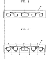
- the microfluidic channel 10 has a structure as illustrated in FIG. 1, which is a plan view of the microfluidic channel 10.
- the microfluidic channel 10 includes one sample detection part, three control detection parts, and two dye/buffer inlet parts.
- Each of the sample and control detection parts has a sample inlet 1 or a control inlet 2, which are connected to the liquid outlets of the sample and control reservoirs, respectively, and an outlet 5, and includes antibodies 13 immobilized on an inner surface.
- the dye/buffer inlet parts have two dye inlets 3 connected to liquid outlets of the dye reservoir and a buffer inlet port 4.
- the antibodies 13 that specifically bind to a target protein are attached to the four detection parts in the microfluidic channel 10.
- the four outlets 5 are connected to the microfluidic channel 10 to externally discharge air and liquid that have been used in the four detection parts.
- the sample and control detection parts may be manufactured to have the same volume so that equal volumes of a sample and a control can be supplied into the sample and control detection parts, respectively, when an equal pressure is applied to both the sample and control reservoirs.
- the length of a portion of the microfluidic channel between the dye inlet 3 of the dye/buffer inlet part and the outlet 5 of the sample detection part may equal to the length of a portion of the microfluidic channel between the dye inlet 3 of the dye/buffer inlet part and the outlet 5 of one of the control detection parts so that equal volumes of a dye and a buffer can flow toward the sample and the control at the same rate when an equal pressure is applied from the compressed-air inlet 6.
- the length of a portion of the microfluidic channel between the buffer inlet port of the dye/buffer inlet part and the outlet of the sample detection part may be equal to the length of a portion of the microfluidic channel between the dye inlet of the dye/buffer inlet part and the outlet of one of the control detection parts.
- the microfluidic channel 10 may be formed in a polydimethylsiloxan (PDMS) substrate, a glass substrate, a silicon substrate, etc.
- the microfluidic channel 10 may have a width of 50-500 ⁇ m and a depth of 10-200 ⁇ m.
- a substrate with the microfluidic channel 10 is combined with, for example, a glass chip, placed in a cartridge, and sealed using, for example, O-rings.
- the microfluidic system includes a compressed-air storage tank connected to the compressed-air inlets 6 by valves 11c, a buffer storage tank connected to the buffer inlet ports 4 by valves 11b, and a reader that measures the degrees of antigen-antibody reactions in the sample and control detection parts based on variations in dye color.
- Compressed air and a buffer are stored in the compressed-air storage tank and the buffer storage tank, respectively.
- the compressed air and the buffer are forced to flow into the cartridge by a pump 12 that is connected commonly to the compressed-air storage tank and the buffer storage tank.
- the reader used in the microfluidic system according to the present invention includes a photodetector that measures color variation data for the sample and the control reacted in the microfluidic channel 10.
- a photodetector that measures color variation data for the sample and the control reacted in the microfluidic channel 10. Any common photodetector that is widely used in the field may be used provided that it can detect a fluorescent signal, a chemiluminescent signal, a phosphorescent signal, etc.
- the microfluidic system includes fluid ports as fluid exchange paths between the cartridge and each of the compressed-air storage tank, the buffer storage tank, and other external devices.
- the fluid ports include the compressed-air inlet ports 6 that are located on the tops of the reservoirs of the cartridge reservoir part 9, respectively, and allow compressed air blown from the compressed-air storage tank to pass, the buffer inlet port 4 connected to the microfluidic channel 10 and through which a buffer is supplied, and the outlets 5 connected to the microfluidic channel 10 and through which used gas and liquid are externally discharged from the microfluidic channel 10.
- valves 11a, 11b, and 11c Flows of fluid through the compressed-air inlet ports 6, the buffer inlet port 4, and the outlets 5 are controlled by the valves 11a, 11b, and 11c that are operated by an automated control system, such as a computer.
- the valves 11a, 11b, and 11c may be controlled by means of a computer program, such as LabVlew TM .
- Each of the fluid ports is connected to one of the valves 11a, 11b, and 11c according to their function.
- Valves which are connected to the compressed-air inlet ports 6 are three-way valves that are closed to allow external air to flow into the compressed-air inlet ports 6 and are opened toward a pump 12 so that compressed air enters the compressed-air inlet ports 6.
- a valve which is connected to the buffer inlet port 4 is a two-way valve that is closed to block a buffer in the buffer storage tank from entering the microfluidic channel 10 and is opened to allow the buffer to enter the microfluidic channel 10.
- Valves which are connected to the outlets 5 are two-way valves that are opened to externally discharge gas and liquid used in the microfluidic channel 10.
- a cartridge according to an embodiment of the present invention that includes the cartridge reservoir part 9, the microfluidic channel 10, the compressed-air inlets 6, the buffer inlet port 4, and the outlets 5, is schematically illustrated in FIG. 3.
- a 3-dimensional image of the cartridge illustrated using computer graphics is shown in FIG. 5.
- the cartridge is designed to be detachable from the automated fluidic system according to the present invention for easy measurement of color variation data for samples in the cartridge and for easy exchange, repair, and maintenance of the cartridge.
- FIG. 4 is a schematic view of an automated microfluidic system according to an embodiment of the present invention, which includes the cartridge, the compressed-air storage tank, the buffer storage tank, and the reader.
- the antigen-antibody reaction when detecting a target protein in a sample using the automated microfluidic system according to the present invention, may be induced by supplying compressed air through the compressed-air inlet ports to move the sample in the sample reservoir and the control in the control reservoir into the sample and control detection parts, respectively.
- Supplying compressed air is initiated by turning on a switch of the pump 12 connected to the compressed-air storage tank.
- the pump 12 applies a predetermined pressure to the compressed-air storage tank and the buffer storage tank.
- the cartridge is not affected by the pressure.
- valves 11c which are connected to the sample and control reservoirs are opened by an automated valve control system, the sample and the control flow along the microfluidic channel 10 and reach the sample and control detection parts, respectively, so that antigen-antibody reactions between the antibodies attached to the internal surface of the microfluidic channel and antigens (target protein) of the sample and the control take place.
- the valves 11c that are connected between the compressed-air inlet ports 6 and the sample and control reservoirs are closed by the valve control system, the valves 11a and 11b that are connected to the buffer inlet port 4 and the outlets 5 are opened so that the buffer flows into and fills the microfluidic channel 10 connected to the buffer inlet port 4.
- the buffer fills the cartridge reservoir part 9 up to the upper hydrophobic barrier 7.
- valve 11b connected to the buffer inlet port 4 is closed, and the valves 11c that are connected between the compressed-air inlet ports 6 and the dye reservoir are opened so that the dye in the dye storage reservoir flows into the microfluidic channel 10 through the dye inlets 3 of the dye/buffer inlet part.
- the distances between the dye inlets 3 and the outlets 5 of the sample and control detection parts are the same so that equal amounts of a dye flows along the microfluidic channel 10 into the sample and control detection parts to which the antibodies 13 are attached.
- valves 11c connected between the dye reservoir and the compressed-air inlet ports 6 are closed, and the valve 11b connected to the buffer inlet port 4 is opened to allow the buffer to flow along the entire microfluidic channel 10 and wash off the dye remaining in the sample and control detection parts.
- color variation data for the sample and control reacted in the sample and control detection parts, respectively, of the cartridge are read by a photodetector. It can be determined whether a particular protein is present in the sample based on the read color variation data. The concentration of the particular protein in the sample can be calculated using a calibration curve of the control.
- an automated microfluidic system that detects a particular protein in a biological sample by ELISA can automate a series of assaying processes, beginning with sample injection and ending with detection, with a simple structure, thereby allowing for convenient and quick detection of a particular protein in a biological sample without requiring skillful, elaborate manipulations by an operator.
Claims (12)
- Système micro-fluidique automatisé qui détecte une protéine dans un échantillon biologique, le système comportant :une partie de réservoir de cartouche (9) incluant un réservoir d'échantillon, un réservoir de colorant, et une pluralité de réservoirs de témoin qui contiennent des solutions témoin de diverses concentrations de la protéine d'intérêt, chacun parmi le réservoir d'échantillon, le réservoir de colorant et les réservoirs de témoin ayant une barrière supérieure hydrophobe (7) connectée à une entrée d'air comprimé (6) et une barrière inférieure hydrophobe (8) connectée à une sortie de liquide,une cartouche ayant un canal micro-fluidique (10) qui inclut une partie de détection d'échantillon, une pluralité de parties de détection de témoin, et une partie d'entrée de colorant/tampon, chacune parmi la partie de détection d'échantillon et les parties de détection de témoin ont des entrées connectées aux sorties de liquide du réservoir d'échantillon et des réservoirs de témoin, respectivement, une sortie, et des anticorps (13) immobilisés sur une surface intérieure, la partie d'entrée de colorant/tampon ayant une entrée de colorant (3) connectée à une sortie de liquide du réservoir de colorant et un orifice d'entrée de tampon (4),un réservoir de stockage d'air comprimé connecté aux entrées d'air comprimé (6) du réservoir d'échantillon, des réservoirs de colorant, et des réservoirs de témoin par des vannes (11c), un réservoir de stockage de tampon connecté aux orifices d'entrée de tampon (4) par des vannes, etun lecteur qui mesure les degrés de réaction antigène-anticorps dans l'échantillon et des parties de détection de témoin basées sur des variations de couleur du colorant.
- Système micro-fluidique automatisé selon la revendication 1, dans lequel la barrière hydrophobe supérieure (7) et la barrière hydrophobe inférieure (8) laissent uniquement passer de l'air, pas un liquide, dans une pression atmosphérique.
- Système micro-fluidique automatisé selon la revendication 1, dans lequel la barrière hydrophobe supérieure (7) et la barrière hydrophobe inférieure (8) sont poreuses, et la barrière hydrophobe inférieure (8) a une taille moyenne de pore plus grande que la barrière hydrophobe supérieure (7).
- Système micro-fluidique automatisé selon la revendication 3, dans lequel la barrière hydrophobe supérieure (7) a un diamètre moyen de pore qui se trouve dans la plage de 0,2 µm à 1 µm, et la barrière hydrophobe inférieure (8) a un diamètre moyen de pore qui se trouve dans la plage de 2 µm à 20 µm.
- Système micro-fluidique automatisé selon la revendication 1, dans lequel la barrière hydrophobe supérieure (7) et la barrière hydrophobe inférieure (8) sont constituées de membranes de polytétrafluoroéthylène poreux.
- Système micro-fluidique automatisé selon la revendication 1, comportant de plus une pompe (12) connectée au réservoir de stockage d'air comprimé et au réservoir de stockage de tampon.
- Système micro-fluidique automatisé selon la revendication 1, dans lequel la partie de détection d'échantillon et les parties de détection de témoin ont le même volume.
- Système micro-fluidique automatisé selon la revendication 1, dans lequel la longueur d'une partie du canal micro-fluidique (10) entre l'entrée de colorant (3) de la partie d'entrée de colorant/tampon et la sortie (5) de la partie de détection d'échantillon est égale à la longueur d'une partie du canal micro-fluidique (10) entre l'entrée de colorant (3) de la partie d'entrée de colorant/tampon et la sortie (5) d'une des parties de détection de témoin.
- Système micro-fluidique automatisé selon la revendication 1, dans lequel la longueur d'une partie du canal micro-fluidique (10) entre l'orifice d'entrée de tampon (4) de la partie d'entrée de colorant/tampon et la sortie (5) de la partie de détection d'échantillon est égale à la longueur d'une partie du canal micro-fluidique (10) entre l'entrée de colorant (3) de la partie d'entrée de colorant/tampon et la sortie (5) d'une des parties de détection de témoin.
- Système micro-fluidique automatisé selon la revendication 1, dans lequel les soupapes (11c) qui connectent les entrées d'air comprimé (6) et le réservoir de stockage d'air comprimé sont des soupapes à trois voies qui sont fermées pour permettre à l'air externe de circuler dans les orifices d'entrée d'air comprimé et sont ouvertes vers le réservoir de stockage d'air comprimé.
- Système micro-fluidique automatisé selon la revendication 1, comportant de plus un dispositif de commande qui commande l'ouverture et la fermeture des sorties (5) de la partie de détection d'échantillon et des parties de détection de témoin.
- Procédé pour détecter une protéine dans un échantillon biologique utilisant le système micro-fluidique automatisé selon la revendication 1, le procédé comportant les étapes consistant à :alimenter de l'air comprimé à travers les entrées d'air comprimé (6) pour déplacer un échantillon dans le réservoir d'échantillon et des témoins dans les réservoirs de témoin dans la partie de détection d'échantillon et les parties de détection de témoin, respectivement, pour induire des réactions antigène-anticorps à l'intérieur ; laver la partie de détection d'échantillon et les parties de détection de témoin en alimentant un tampon à travers l'orifice d'entrée de tampon (4) ;alimenter de l'air comprimé à travers les entrées d'air comprimé (6) pour déplacer un colorant dans le réservoir de colorant à travers la partie d'entrée de colorant/tampon dans la partie de détection d'échantillon et les parties de détection de témoin ;laver la partie de détection, d'échantillon et les parties de détection de témoin en alimentant un tampon à travers l'orifice d'entrée de tampon (4) ; etdétecter si la protéine existe dans l'échantillon biologique et quantifier la protéine sur la base des données de variation de couleur obtenues à partir des réactions antigène-anticorps dans la partie de détection d'échantillon et les parties de détection de témoin.
Applications Claiming Priority (2)
| Application Number | Priority Date | Filing Date | Title |
|---|---|---|---|
| KR10-2003-0003668A KR100537504B1 (ko) | 2003-01-20 | 2003-01-20 | 생물학적 시료 내에서의 단백질 검출을 위한 자동화된 유동 시스템 |
| KR2003003668 | 2003-01-20 |
Publications (2)
| Publication Number | Publication Date |
|---|---|
| EP1441229A1 EP1441229A1 (fr) | 2004-07-28 |
| EP1441229B1 true EP1441229B1 (fr) | 2006-12-27 |
Family
ID=36751403
Family Applications (1)
| Application Number | Title | Priority Date | Filing Date |
|---|---|---|---|
| EP04001087A Expired - Fee Related EP1441229B1 (fr) | 2003-01-20 | 2004-01-20 | Méthode et système micro-fluidique automatisé pour la détection de protéines dans des échantillons biologiques |
Country Status (6)
| Country | Link |
|---|---|
| US (1) | US6989130B2 (fr) |
| EP (1) | EP1441229B1 (fr) |
| JP (1) | JP3989446B2 (fr) |
| KR (1) | KR100537504B1 (fr) |
| CN (1) | CN1254686C (fr) |
| DE (1) | DE602004003842T2 (fr) |
Families Citing this family (29)
| Publication number | Priority date | Publication date | Assignee | Title |
|---|---|---|---|---|
| US7373255B2 (en) * | 2003-06-06 | 2008-05-13 | Biacore Ab | Method and system for determination of molecular interaction parameters |
| US20050191665A1 (en) * | 2003-12-29 | 2005-09-01 | Xing Su | Composite organic-inorganic nanoclusters |
| US8168133B2 (en) * | 2005-05-09 | 2012-05-01 | Wisconsin Alumni Research Foundation | Device for performing a high throughput assay |
| US7410763B2 (en) * | 2005-09-01 | 2008-08-12 | Intel Corporation | Multiplex data collection and analysis in bioanalyte detection |
| KR100749939B1 (ko) | 2006-08-09 | 2007-08-16 | 대한민국 | 검출항체 자동주입장치 |
| WO2008063406A2 (fr) * | 2006-11-08 | 2008-05-29 | Indermuhle Pierre Francois | Plateforme pour lier des essais avec une double capacité de multiplexage |
| US8146448B2 (en) * | 2007-06-29 | 2012-04-03 | Griffin Analytical Technologies, Llc | Apparatus for mobile collection of atmospheric sample for chemical analysis |
| JP5173723B2 (ja) * | 2008-10-07 | 2013-04-03 | ローム株式会社 | マイクロチップ |
| US20120048884A1 (en) * | 2009-04-27 | 2012-03-01 | Zhenfeng Wang | Apparatus and method for dispensing a liquid |
| GB0913228D0 (en) | 2009-07-29 | 2009-09-02 | Iti Scotland Ltd | Loading element |
| KR101034783B1 (ko) | 2009-09-24 | 2011-05-17 | 한국과학기술원 | 면역반응 검사장치용 반응부 및 이를 구비하는 다중 면역반응 검사장치 |
| ITTO20100068U1 (it) * | 2010-04-20 | 2011-10-21 | Eltek Spa | Dispositivi microfluidici e/o attrezzature per dispositivi microfluidici |
| US8596340B1 (en) | 2010-10-13 | 2013-12-03 | Horn-Barber Technologies, LLC | Apparatus for heating liquid samples for analysis |
| KR101821410B1 (ko) * | 2011-01-10 | 2018-01-23 | 엘지전자 주식회사 | 마이크로 유체 디바이스 및 그의 제어 방법과 버블 제어 방법 |
| KR101356628B1 (ko) | 2011-11-30 | 2014-02-04 | 한국과학기술원 | 다중 바이오마커 동시 면역반응검사 방법 및 장치 |
| FI124909B (fi) * | 2012-02-03 | 2015-03-13 | Timo Kalevi Korpela | Mekaaninen pesu- ja mittauslaite ja menetelmä analyysin suorittamiseksi |
| CN103439484B (zh) * | 2013-08-13 | 2015-12-23 | 武汉血液中心 | 一种显色质控物及其应用 |
| US10082500B2 (en) | 2013-08-22 | 2018-09-25 | Franz Baudenbacher | Device and method for detecting a target analyte |
| US9956557B2 (en) | 2015-07-24 | 2018-05-01 | HJ Science & Technology, Inc. | Reconfigurable microfluidic systems: microwell plate interface |
| US9956558B2 (en) | 2015-07-24 | 2018-05-01 | HJ Science & Technology, Inc. | Reconfigurable microfluidic systems: homogeneous assays |
| US9733239B2 (en) | 2015-07-24 | 2017-08-15 | HJ Science & Technology, Inc. | Reconfigurable microfluidic systems: scalable, multiplexed immunoassays |
| JP2019536993A (ja) * | 2016-10-07 | 2019-12-19 | ベーリンガー インゲルハイム フェトメディカ ゲーエムベーハーBoehringer Ingelheim Vetmedica GmbH | サンプルを検査するためのカートリッジ、分析システム、及び方法 |
| KR101863315B1 (ko) * | 2017-02-24 | 2018-06-29 | 계명대학교 산학협력단 | 자동 주입형 진단 키트 장비 |
| KR101992861B1 (ko) * | 2017-10-12 | 2019-06-27 | 한국과학기술원 | 미세유로 제어시스템 및 이의 제어방법 |
| KR102425126B1 (ko) * | 2018-02-12 | 2022-07-29 | 한국전자통신연구원 | 바이오 반응 유체 제어장치, 바이오 반응 시스템 및 바이오 반응 유체 제어방법 |
| TWI675106B (zh) * | 2018-03-21 | 2019-10-21 | 緯創資通股份有限公司 | 液體處理模組、液體檢測系統及利用液體處理模組進行檢測的檢測方法 |
| US11376589B2 (en) | 2018-04-30 | 2022-07-05 | Protein Fluidics, Inc. | Valveless fluidic switching flowchip and uses thereof |
| EP3976259A4 (fr) * | 2019-05-28 | 2023-06-07 | Illumina Inc | Systèmes et procédés de rinçage à deux phases |
| RU200301U1 (ru) * | 2019-05-31 | 2020-10-15 | Общество с ограниченной ответственностью "ИНФРАКАП-МЕДИЦИНА" | Микрофлюидный чип для проведения многопараметрического иммуноанализа |
Family Cites Families (22)
| Publication number | Priority date | Publication date | Assignee | Title |
|---|---|---|---|---|
| US4381099A (en) * | 1981-04-28 | 1983-04-26 | The Penmont Company | Faucet for frozen carbonated beverage machine |
| US4598628A (en) * | 1984-05-21 | 1986-07-08 | 4 Square Motors | Rotary hydraulic engine having oppositely disposed pistons in a scotch yoke assembly |
| US4895706A (en) * | 1986-10-28 | 1990-01-23 | Costar Corporation | Multi-well filter strip and composite assemblies |
| US5219529A (en) * | 1987-07-07 | 1993-06-15 | Unisyn Technologies, Inc. | Cartridge assembly |
| US5321123A (en) * | 1991-07-02 | 1994-06-14 | The Scripps Research Institute | Protein S polypeptides and anti-peptide antibodies that inhibit protein S binding to C4B binding protein, diagnostic systems and therapeutic methods |
| WO1994019690A1 (fr) * | 1993-02-17 | 1994-09-01 | Cardiovascular Diagnostics, Inc. | Dosage immunologique et dosage par affinite en cascade par voie seche |
| AU7043594A (en) * | 1993-05-28 | 1994-12-20 | Ensys Environmental Products, Inc. | A polychlorinated biphenyls (pcb) immunoassay method, its components and a kit for use in performing the same |
| US5472672A (en) * | 1993-10-22 | 1995-12-05 | The Board Of Trustees Of The Leland Stanford Junior University | Apparatus and method for polymer synthesis using arrays |
| US5603351A (en) * | 1995-06-07 | 1997-02-18 | David Sarnoff Research Center, Inc. | Method and system for inhibiting cross-contamination in fluids of combinatorial chemistry device |
| US5697132A (en) * | 1996-06-17 | 1997-12-16 | Morganthal Llc | System and method for automated mixing and delivery of embalming fluid to a cadaver |
| CA2389358C (fr) * | 1996-12-31 | 2008-07-15 | Genometrix Incorporated | Procede et dispositif d'analyse moleculaire multiplexee |
| US6146595A (en) * | 1998-02-10 | 2000-11-14 | Balazs Analytical Laboratory | Closed evaporator system for preparing samples for analysis |
| US6117396A (en) * | 1998-02-18 | 2000-09-12 | Orchid Biocomputer, Inc. | Device for delivering defined volumes |
| US6033911A (en) * | 1998-02-27 | 2000-03-07 | Hamilton Company | Automated assaying device |
| US6093869A (en) * | 1998-06-29 | 2000-07-25 | The Procter & Gamble Company | Disposable article having a responsive system including a feedback control loop |
| US6485690B1 (en) * | 1999-05-27 | 2002-11-26 | Orchid Biosciences, Inc. | Multiple fluid sample processor and system |
| WO2000078456A1 (fr) * | 1999-06-19 | 2000-12-28 | Orchid Biosciences, Inc. | Interface de dispositif microfluidique |
| US6395232B1 (en) * | 1999-07-09 | 2002-05-28 | Orchid Biosciences, Inc. | Fluid delivery system for a microfluidic device using a pressure pulse |
| CN1378485A (zh) | 1999-08-12 | 2002-11-06 | Ut-巴特勒有限公司 | 用于可控操纵小体积的微流控装置 |
| CN1425133A (zh) | 1999-10-13 | 2003-06-18 | 西格雷特生物科学有限公司 | 检测和识别试样中分子事件的系统和方法 |
| US6594432B2 (en) * | 2000-02-22 | 2003-07-15 | Genospectra, Inc. | Microarray fabrication techniques and apparatus |
| US6729352B2 (en) * | 2001-06-07 | 2004-05-04 | Nanostream, Inc. | Microfluidic synthesis devices and methods |
-
2003
- 2003-01-20 KR KR10-2003-0003668A patent/KR100537504B1/ko not_active IP Right Cessation
-
2004
- 2004-01-19 JP JP2004010366A patent/JP3989446B2/ja not_active Expired - Fee Related
- 2004-01-20 US US10/761,846 patent/US6989130B2/en not_active Expired - Lifetime
- 2004-01-20 CN CNB2004100059092A patent/CN1254686C/zh not_active Expired - Fee Related
- 2004-01-20 DE DE602004003842T patent/DE602004003842T2/de not_active Expired - Lifetime
- 2004-01-20 EP EP04001087A patent/EP1441229B1/fr not_active Expired - Fee Related
Also Published As
| Publication number | Publication date |
|---|---|
| CN1254686C (zh) | 2006-05-03 |
| DE602004003842D1 (de) | 2007-02-08 |
| DE602004003842T2 (de) | 2007-04-12 |
| CN1517712A (zh) | 2004-08-04 |
| US6989130B2 (en) | 2006-01-24 |
| JP3989446B2 (ja) | 2007-10-10 |
| EP1441229A1 (fr) | 2004-07-28 |
| KR100537504B1 (ko) | 2005-12-19 |
| KR20040066564A (ko) | 2004-07-27 |
| JP2004226403A (ja) | 2004-08-12 |
| US20040152200A1 (en) | 2004-08-05 |
Similar Documents
| Publication | Publication Date | Title |
|---|---|---|
| EP1441229B1 (fr) | Méthode et système micro-fluidique automatisé pour la détection de protéines dans des échantillons biologiques | |
| US7820109B2 (en) | Testing chip and micro analysis system | |
| US8778696B2 (en) | Processing units and methods for the processing of liquid samples | |
| US8133456B2 (en) | Microreactor and method of liquid feeding making use of the same | |
| US11325120B2 (en) | Specimen treatment chip, specimen treatment apparatus, and specimen treatment method | |
| US20040203136A1 (en) | Microfluidics devices and methods of diluting samples and reagents | |
| US8940249B2 (en) | System for the analysis of liquid samples | |
| US20210370293A1 (en) | Micro-fluidic Chip and Analytical Instrument Having the Same | |
| CN108761055B (zh) | 一种微流控芯片及具有该微流控芯片的分析仪器 | |
| JP2002236131A (ja) | マイクロチップ | |
| CN103429331A (zh) | 用于形成乳液的系统 | |
| WO2006019590A1 (fr) | Appareils et procédés d’analyse d’échantillons dans un microscope optique | |
| JP2000097948A (ja) | 化学分析装置 | |
| US20170028403A1 (en) | Microfluidics module and cartridge for immunological and molecular diagnosis in an analysis machine | |
| US20150165435A1 (en) | Autonomous and programmable sequential flow of solutions in capillary microfluidics | |
| US10746733B2 (en) | Microfluidic device having injection-molded fluidics layer, and method of making same | |
| JP2006284451A (ja) | 検体中の標的物質を分析するためのマイクロ総合分析システム | |
| KR20050110810A (ko) | 적응형 미세 유체 칩 및 이를 이용한 미세 유체 제어 장치및 방법 | |
| KR102065301B1 (ko) | 미세 주입기를 가진 미세유체분석칩 및 그 제조 방법 및 그 사용 방법 | |
| KR101614333B1 (ko) | 미세유체 혼합장치 | |
| EP3381555A1 (fr) | Système et procédé de manipulation et/ou de distribution de liquide | |
| JP2006275735A (ja) | マイクロ総合分析システム |
Legal Events
| Date | Code | Title | Description |
|---|---|---|---|
| PUAI | Public reference made under article 153(3) epc to a published international application that has entered the european phase |
Free format text: ORIGINAL CODE: 0009012 |
|
| 17P | Request for examination filed |
Effective date: 20040120 |
|
| AK | Designated contracting states |
Kind code of ref document: A1 Designated state(s): AT BE BG CH CY CZ DE DK EE ES FI FR GB GR HU IE IT LI LU MC NL PT RO SE SI SK TR |
|
| AX | Request for extension of the european patent |
Extension state: AL LT LV MK |
|
| RIN1 | Information on inventor provided before grant (corrected) |
Inventor name: DESHMUKH A JAY |
|
| AKX | Designation fees paid |
Designated state(s): DE FR GB |
|
| GRAP | Despatch of communication of intention to grant a patent |
Free format text: ORIGINAL CODE: EPIDOSNIGR1 |
|
| GRAS | Grant fee paid |
Free format text: ORIGINAL CODE: EPIDOSNIGR3 |
|
| GRAA | (expected) grant |
Free format text: ORIGINAL CODE: 0009210 |
|
| AK | Designated contracting states |
Kind code of ref document: B1 Designated state(s): DE FR GB |
|
| REG | Reference to a national code |
Ref country code: GB Ref legal event code: FG4D |
|
| REF | Corresponds to: |
Ref document number: 602004003842 Country of ref document: DE Date of ref document: 20070208 Kind code of ref document: P |
|
| ET | Fr: translation filed | ||
| RIN2 | Information on inventor provided after grant (corrected) |
Inventor name: DESHMUKH A JAY |
|
| PLBE | No opposition filed within time limit |
Free format text: ORIGINAL CODE: 0009261 |
|
| STAA | Information on the status of an ep patent application or granted ep patent |
Free format text: STATUS: NO OPPOSITION FILED WITHIN TIME LIMIT |
|
| 26N | No opposition filed |
Effective date: 20070928 |
|
| PGFP | Annual fee paid to national office [announced via postgrant information from national office to epo] |
Ref country code: FR Payment date: 20090113 Year of fee payment: 6 |
|
| REG | Reference to a national code |
Ref country code: FR Ref legal event code: ST Effective date: 20100930 |
|
| PG25 | Lapsed in a contracting state [announced via postgrant information from national office to epo] |
Ref country code: FR Free format text: LAPSE BECAUSE OF NON-PAYMENT OF DUE FEES Effective date: 20100201 |
|
| PGFP | Annual fee paid to national office [announced via postgrant information from national office to epo] |
Ref country code: GB Payment date: 20141216 Year of fee payment: 12 |
|
| PGFP | Annual fee paid to national office [announced via postgrant information from national office to epo] |
Ref country code: DE Payment date: 20141216 Year of fee payment: 12 |
|
| REG | Reference to a national code |
Ref country code: DE Ref legal event code: R119 Ref document number: 602004003842 Country of ref document: DE |
|
| GBPC | Gb: european patent ceased through non-payment of renewal fee |
Effective date: 20160120 |
|
| PG25 | Lapsed in a contracting state [announced via postgrant information from national office to epo] |
Ref country code: GB Free format text: LAPSE BECAUSE OF NON-PAYMENT OF DUE FEES Effective date: 20160120 Ref country code: DE Free format text: LAPSE BECAUSE OF NON-PAYMENT OF DUE FEES Effective date: 20160802 |