EP0282611A1 - Méthode et appareil pour enregistrer de l'information sur un film photographique développé - Google Patents
Méthode et appareil pour enregistrer de l'information sur un film photographique développé Download PDFInfo
- Publication number
- EP0282611A1 EP0282611A1 EP87103813A EP87103813A EP0282611A1 EP 0282611 A1 EP0282611 A1 EP 0282611A1 EP 87103813 A EP87103813 A EP 87103813A EP 87103813 A EP87103813 A EP 87103813A EP 0282611 A1 EP0282611 A1 EP 0282611A1
- Authority
- EP
- European Patent Office
- Prior art keywords
- film
- sound track
- emulsion
- area
- information
- Prior art date
- Legal status (The legal status is an assumption and is not a legal conclusion. Google has not performed a legal analysis and makes no representation as to the accuracy of the status listed.)
- Withdrawn
Links
Images


Classifications
-
- G—PHYSICS
- G11—INFORMATION STORAGE
- G11B—INFORMATION STORAGE BASED ON RELATIVE MOVEMENT BETWEEN RECORD CARRIER AND TRANSDUCER
- G11B7/00—Recording or reproducing by optical means, e.g. recording using a thermal beam of optical radiation by modifying optical properties or the physical structure, reproducing using an optical beam at lower power by sensing optical properties; Record carriers therefor
- G11B7/002—Recording, reproducing or erasing systems characterised by the shape or form of the carrier
- G11B7/003—Recording, reproducing or erasing systems characterised by the shape or form of the carrier with webs, filaments or wires, e.g. belts, spooled tapes or films of quasi-infinite extent
- G11B7/0032—Recording, reproducing or erasing systems characterised by the shape or form of the carrier with webs, filaments or wires, e.g. belts, spooled tapes or films of quasi-infinite extent for moving-picture soundtracks, i.e. cinema
-
- G—PHYSICS
- G03—PHOTOGRAPHY; CINEMATOGRAPHY; ANALOGOUS TECHNIQUES USING WAVES OTHER THAN OPTICAL WAVES; ELECTROGRAPHY; HOLOGRAPHY
- G03B—APPARATUS OR ARRANGEMENTS FOR TAKING PHOTOGRAPHS OR FOR PROJECTING OR VIEWING THEM; APPARATUS OR ARRANGEMENTS EMPLOYING ANALOGOUS TECHNIQUES USING WAVES OTHER THAN OPTICAL WAVES; ACCESSORIES THEREFOR
- G03B17/00—Details of cameras or camera bodies; Accessories therefor
- G03B17/24—Details of cameras or camera bodies; Accessories therefor with means for separately producing marks on the film, e.g. title, time of exposure
-
- G—PHYSICS
- G03—PHOTOGRAPHY; CINEMATOGRAPHY; ANALOGOUS TECHNIQUES USING WAVES OTHER THAN OPTICAL WAVES; ELECTROGRAPHY; HOLOGRAPHY
- G03C—PHOTOSENSITIVE MATERIALS FOR PHOTOGRAPHIC PURPOSES; PHOTOGRAPHIC PROCESSES, e.g. CINE, X-RAY, COLOUR, STEREO-PHOTOGRAPHIC PROCESSES; AUXILIARY PROCESSES IN PHOTOGRAPHY
- G03C11/00—Auxiliary processes in photography
- G03C11/02—Marking or applying text
-
- G—PHYSICS
- G03—PHOTOGRAPHY; CINEMATOGRAPHY; ANALOGOUS TECHNIQUES USING WAVES OTHER THAN OPTICAL WAVES; ELECTROGRAPHY; HOLOGRAPHY
- G03B—APPARATUS OR ARRANGEMENTS FOR TAKING PHOTOGRAPHS OR FOR PROJECTING OR VIEWING THEM; APPARATUS OR ARRANGEMENTS EMPLOYING ANALOGOUS TECHNIQUES USING WAVES OTHER THAN OPTICAL WAVES; ACCESSORIES THEREFOR
- G03B2217/00—Details of cameras or camera bodies; Accessories therefor
- G03B2217/24—Details of cameras or camera bodies; Accessories therefor with means for separately producing marks on the film
- G03B2217/242—Details of the marking device
- G03B2217/243—Optical devices
Definitions
- This invention relates to a method and apparatus for writing information on exposed photographic film.
- Such information may include sound tracks for cinematic film or alpha-numeric characters and like symbols for still photgraphic film.
- the first step in all prior art methods is to record the translated dialogue with a audio magnetic tape recorder.
- Well-known methods are used to synchronize the recorded dialogue to the actor's lip movements in the existing film.
- the resulting audio tape is normally called the new magnetic dialogue.
- the new magnetic dialogue is now mixed with prerecorded, synchronized music and special sound effects in a well-known manner and re-recorded creating a composite final mix tape.
- the audio signal on the final mix tape is transferred to the cinematic film by means of one of several methods.
- Another prior art method was to prepare an optical sound track with the final mix audio information by photographically exposing the optical sound track prior to processing of the film by means of a process called electroprinting.
- This process involved exposing the emulsion directly on the copy print stock by means of a light source passing through a narrow, variable-area slit located in front of the sound track area on the film. The area of the slit is modulated by the recorded audio information by means of a moving wedge which is driven by the audio signal.
- the problem with the electroprint system was that it could not produce a optical sound track with a satisfactory quality because the quality of the track depended on a number of variables which affected the contrast of the resulting track. Many of these variables could not be accurately controlled such as, processor contrast control, developer formula, temperature and exposure time.
- the quality of the finished optical track required a fine grain, high-contrast emulsion and such an emulsion was not ordinarily used in the picture area of either positive or negative cinematic copy film.
- optical printing on internegative film Another process used to transfer the optical information to the photographic film is called optical printing on internegative film.
- the sound track is applied to the photograhic film in two steps. First the magnetic track is transferred and exposed on special film which has a fine grain and high contrast emulsion. The sound information is exposed in the optical track area but the film remains clear in the picture area. The original negative picture is separately printed on another negative film (the internegative) leaving a clear optical track area. Finally, the optical track and the internegative picture image are printed onto positive copy stock by contact printing to produce the cinematic film answer print.
- variable density method Two methods have commonly been used with the internegative process to convert the sound information into an optical track.
- the optical track emulsion is exposed by means of a light passing through a narrow slit in front of the sound track area of the film.
- the intensity of the light is varied by modulating the light source by the audio information.
- the problem with the variable density method is that it could not produce sound tracks of predictable quality since the resulting optical track had a continuous grey-scale ranging from clear to opaque.
- the quality of the processed track depends on proper exposure and various processing variables as well as fine-grain film.
- the second method of converting the audio information to an optical sound track is the variable area method.
- the variable area method also involves exposing the emulsion by means of a light source passing through a small slit located in front of the film.
- the intensity of the light source is kept constant and the area of the slit is changed by a moving wedge controlled by the audio information.
- the resulting sound track can also be read by conventional projection equipment, but also requires high contrast emulsion on the optical track of copy print to produce a high-quality track.
- the internegative process with variable area conversion produces a high-quality optical track on normal copy stock, it is the current method used to process copies. But, due to the necessity of a synchronizer to synchronize the printing of the optical track with the picture negative, the method is cumbersome and expensive. Furthermore it is useful only for a certain number of copies at least, as otherwise it is too expensive. Generally nowadays such films can be prepared only at the original film studios and the availability of the dubbed films depends on the capacities of such studios.
- the laser beam can be used to apply the required sound track to any type of cinematic film (negative or positive, black or colour), Super-8 , l6, 35 or 70 mm. etc., and this by economical means which make possible the production of a small number of such films by simple means.
- a wide variety of lasers is available, and it is a matter of choice to select a suitable one according to the nature and material of the film and the required effects.
- the first steps of the process of the invention are identical with the first steps of the conventional process, namely there is obtained a copy of the original film with the original sound track; there is ordered a copy of the magnetic tape of the music and sound effects, there is carried out a sound-by-word translation of the dialogue, taking care to end up with the same number of syllables in each sentence in the translation, recording the translation of the dialogue and recording this on a suitable magnetic tape.
- the new magnetic recording is used to steer and control a transfer optics system which modulates a laser beam which is used to record the desired sound sound track on a copy of the original film an empty dark, opaque sound track ordered for this purpose.
- the composite final mix sound track is used to control a variable area slit mechanism (called a"galvanometer" mask) similar to those used in prior art variable area recording techniques to vaporize a variable area sound track on the processed film.
- a variable area slit mechanism called a"galvanometer” mask
- the laser beam is directed through a rotatable disk containing character outlines in the same manner as performed by well-known phototypesetting systems. In either of the latter two processes, the laser beam is kept at a constant intensity.
- the sound track can be applied by means of the modulated laser beam to the final positive film, it is economical to produce a limited number of copies. No special laboratories are required and this can be done even in daylight.
- the new sound track can be applied to any existing type of cinematic films.
- the electrical signal from a magnetic tape recorder containing the final composite mix tape is used to control a galvanometer mask.
- Constant intensity light from a laser passes through the mask and is focussed, via a suitable optical system, onto a film in a standard film transport.
- the tape recorder and the film transport are synchronized by well-known means so that the laser light vaporizes the emulsion in the sound track area producing a synchronized sound track having a high signal-to-noise ratio.
- FIG. l A system according to the present invention is illustrated in Figure l, which system comprises in combination an audio magnetic tape ll which is used to control and steer the transfer optics l2 whereby the continuous laser beam l3 coming from laser l4 is modulated and the modulated beam l5 is applied to the cinematic film l6 which is moved synchronously by the system l7 which is also connected to the device of the magnetic tape which steers the synchronization.
- Figure 2 of the drawing illustrates a computer-controlled combined system for using a laser beam to either write an optical sound track on cinematic film or to write alpha-numeric characters and the like on a piece of still photographic film.
- the laser light used for marking the film is generated by laser 20l.
- Laser 20l is operated in a well-known manner by an exciter 225 which receives power from power supply 224.
- the selection of laser 20l depends on the application for which the system is being used and the writing speed necessary.
- a laser suitable for use with the illustrative embodiment is a Nd-YAG argon-ion laser.
- An example of such a laser is a model 5052 Nd-YAG laser manufactured by U.S. Laser Corporation, Waldwick, New Jersey. This laser has an adjustable power output up to 2 watts. For the illustrative embodiment the power output is adjusted to l/3 watt power output.
- the laser is operated at 28 amps., 3000 Hz.
- the laser has a light output with a l.06 micron wavelength.
- a harmonic generator is a well-known device which accepts an input light beam at a predetermined frequency and generates an output light beam with a frequency at a harmonic of the input frequency.
- a suitable harmonic generator is a green light harmonic generator which doubles the laser frequency causing a reduction in the l.06 micron wavelength output produced by the laser to a 532 nm. wavelength.
- a laser suitable for use with the illustrative embodiment is a pulsed UV eximer laser.
- the light output is created by a fast transverse electric discharge in a mixture of gases, including helium, fluorine and an appropriate rare gas.
- An eximer laser suitable for use with the illustrative embodiment is a model 2400 laser manufactured by Questec, Inc., Bedford, Massachusetts. With this laser the output wavelength of the light depends on the rare gas used. For example, the laser develops an output with a wavelength of l93 nm.
- a xenon-fluorine mixture produces and output wavelength of 35l nm.
- the best results with the illustrative embodiment have been obtained using a mixture of xenon and chlorine gas with an output wavelength of 308 nm.
- the laser is operated at 35 watts output, with a frequency of 0.2-l00 Hz and a pulse energy of 350 millijoules per cm2 and a 20-nanosecond pulse duration.
- the light output pulse rate is l75 pulses per second.
- a harmonic generator is not necessary for this laser.
- the light output of the laser is passed through a blender shutter 202 which is a mechanical shutter which can turn the beam on and off under control of the computer 2l2, via controller 223. From the blender shutter, the light beam is reflected via mirrors 23l and 232 to the harmonic generator 203 (if necessary). After passing through the harmonic generator the light beam passes through quartz, fused silica, anti-reflection coated lenses 204 which expand the spot size of the beam to a diameter of l-2 cm. The expanded beam then passes to a dichroic beam splitter 226 which directs the main part of the beam to the film area. A small fraction of the beam energy is reflected in the opposite direction to a second splitter 227 which directs the light to a television camera 205 and/or a binocular eyepiece to permit direct viewing of the beam for focussing purposes.
- a blender shutter 202 is a mechanical shutter which can turn the beam on and off under control of the computer 2l2, via controller 223. From the blender shutter, the light beam is reflected via mirrors 23l and
- the main portion of the beam passes to the modulating portions of the optical system.
- a font disk 207 is used for modulating the beam.
- a galvanometer mask 208 is used for writing sound track information. Control of these devices by computer 2l2 will be discussed in more detail hereinafter.
- Font disk 207 is a stencil disk containing cut-outs of the characters to be written in the appropriate font.
- the disk is specially made from a copper sheet laminated with a clear plastic film which is resistant to the heat of the laser beam and, therefore, does not distort, crumple, crack, burn or melt, and does not lose its transparency.
- the plastic is chosen to transmit most (up to 95%) of the specific laser wavelength.
- Plastics suitable for use with the illustrative embodiment are ACLAR plastics, types 22A and 33C, manufactured by the Allied Chemical Corporation located in New Jersey.
- the purpose of laminating the plastic to the stencil mask is to adhere the center pieces of the enclosed letters such as "O", "P", "B”, etc. and to permit the ability to design and create a wide range of artistic drawings on the mask which can be projected on the film via the laser beam.
- Galvanometer 208 is a standard device which is the same as that presently used in variable area transfer system previously discussed.
- the modulated laser beam is focused to a spot by an objective lens 209 onto the film located on table 2l0.
- the size of the spot depends on the image to be written.
- the cinematic film is placed on a standard film transport which moves the film between reels 2l8 and 2l9.
- the film is placed on an X-Y table which can be moved precise distances in either the X or Y direction by means of stepper motors controlled by computer 2l2.
- Both the film transport and the X-Y table are standard components whose operation is well-known.
- Alpha-numeric and the like graphic characters are written by the system under control of computer 2l2 using monitor screen 2l4, data store 2l3, font disk controller 222 and font disk 207.
- the tape recorder 2l5, galvanometer controller 22l and galvanometer mask 208 are not used.
- computer 2l2 opens switch 230 to disconnect controller 222 to cause it to open the mask 208 to its maximum opening.
- the optical path of the system when operating in the character writing mode is shown in Figure 3.
- the light beam from laser 30l passes through harmonic generator 304 (if necessary), disk 307, focussing lens system 309 onto the film located on table 3l0.
- Table 3l0 may be moved in the X and Y directions 320 by means of motors (not shown).
- computer 2l2 controls the blender shutter 202 (via controller 223) and font disk 207 (via controller 222) to produce a sequence of alpha-numeric characters on appropriate positions on the film located on X-Y table 2l0.
- controller 223 controls the blender shutter 202 (via controller 223) and font disk 207 (via controller 222) to produce a sequence of alpha-numeric characters on appropriate positions on the film located on X-Y table 2l0.
- controller 223 controls the blender shutter 202 (via controller 223) and font disk 207 (via controller 222) to produce a sequence of alpha-numeric characters on appropriate positions on the film located on X-Y table 2l0.
- controller 222 controls the blender shutter 202 (via controller 223) and font disk 207 (via controller 222) to produce a sequence of alpha-numeric characters on appropriate positions on the film located on X-Y table 2l0.
- controller 222 controls the blender shutter 202 (via controller 223) and font disk 207 (via controller 222) to produce a sequence
- the characters can be written in two ways.
- the first way is character-by-character.
- the computer controls the font disk to rotate to the proper position for placing the corresponding character stencil in the laser beam.
- computer 2l2 generates coded digital signals which are converted into motor control signals by controller 222.
- controller 222 When the disk has rotated to the proper position, computer 2l2 causes shutter 202 to open via controller 223 to allow the laser beam to pass through the character stencil.
- Font disk 207 can either be continuously spinning or moved to the proper position upon command. In either case the shutter 202 is opened when the proper character is in position.
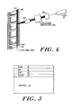
- a typical film emulsion is actually composed of several layers 50-53 on a clear substrate 54.
- the first layer is a layer of black emulsion 50.
- the next layers in sucession are red 5l, blue 52 and yellow 53.
- Each layer is approximately the same thickness and with a pulsed laser a predictable number of pulses are needed to vaporize each layer. For example, with a laser operating with a pulse frequency of l75 Hz, four pulses are required to vaporize each layer.
- the shutter is opened to allow l6 pulses to pass through, all of the emulsion will be vaporized resulting in a clear character being written on the film.
- the top three emulsion layers, 50-52 will be vaporized resulting in a character with a yellow colour. Due to the low power of the laser, if more than l6 pulses are applied to the film, the clear substrate will not be damaged by the beam.
- the computer 2l2 simultaneously generates digital signals which cause the coordinate controller 220 to move the film on table 2l0 to the proper location.
- the system can also be operated in a batch method.
- the characters to be written are first entered into the data store 2l3.
- character codes are retrieved from the data store 2l3 and used by computer 2l2 to control the font disk 207 to write all of the stored characters in an unbroken sequence.
- the optical path of the system when operating in the sound track mode is shown in Figure 4.
- the light beam from laser 40l passes through the harmonic generator 404 (if necessary) and is modulated by galvanometer mask 408.
- the modulated light beam is then focussed onto the film in the film transport.
- the sound track is written from the beginning of the film 4l8 in the forward direction to the end 4l9.
- Another method for writing the optical track with a sound track would be to utilize a laser with a very small spot size.
- the laser beam is then optically or electronically scanned transversely across the optical sound track area at a constant frequency which frequency is much higher than the writing rate.
- the audio information is used to modulate the laser beam, turning the beam on and off at appropriate times.
- the audio signals can be either used to directly modulate the laser beam or, alternatively, the audio signals can be digitized and the digital signals used to modulate the beam. When the beam is on it vaporizes a track across the sound track area. When the beam is off the track remains opaque.
Priority Applications (1)
| Application Number | Priority Date | Filing Date | Title |
|---|---|---|---|
| EP87103813A EP0282611A1 (fr) | 1987-03-16 | 1987-03-16 | Méthode et appareil pour enregistrer de l'information sur un film photographique développé |
Applications Claiming Priority (1)
| Application Number | Priority Date | Filing Date | Title |
|---|---|---|---|
| EP87103813A EP0282611A1 (fr) | 1987-03-16 | 1987-03-16 | Méthode et appareil pour enregistrer de l'information sur un film photographique développé |
Publications (1)
| Publication Number | Publication Date |
|---|---|
| EP0282611A1 true EP0282611A1 (fr) | 1988-09-21 |
Family
ID=8196839
Family Applications (1)
| Application Number | Title | Priority Date | Filing Date |
|---|---|---|---|
| EP87103813A Withdrawn EP0282611A1 (fr) | 1987-03-16 | 1987-03-16 | Méthode et appareil pour enregistrer de l'information sur un film photographique développé |
Country Status (1)
| Country | Link |
|---|---|
| EP (1) | EP0282611A1 (fr) |
Cited By (5)
| Publication number | Priority date | Publication date | Assignee | Title |
|---|---|---|---|---|
| EP0424692A1 (fr) * | 1989-10-24 | 1991-05-02 | Carl Baasel Lasertechnik GmbH | Procédure pour mettre des inscriptions ou marquage sur des diapositives |
| EP0450895A2 (fr) * | 1990-04-02 | 1991-10-09 | Victor Company Of Japan, Limited | Appareil pour enregistrer et reproduire une information |
| FR2721723A1 (fr) * | 1994-06-27 | 1995-12-29 | Cinema Magnetique Comm | Installation d'entraînement et de positionnement d'un film, en particulier en cours de gravure par faisceau laser. |
| EP0782045A1 (fr) | 1995-12-27 | 1997-07-02 | Agfa-Gevaert N.V. | Filmphotographique en couleur à l'halogénure d'argent ayant un support en plastique capable d'être marqué par un laser |
| FR2855884A1 (fr) * | 2003-06-04 | 2004-12-10 | Monal Systems | Mecanisme pour la gravure par un faisceau laser de sous-titres simultanement sur une ou plusieurs images d'un film cinematographique |
Citations (7)
| Publication number | Priority date | Publication date | Assignee | Title |
|---|---|---|---|---|
| DE264713C (fr) * | ||||
| DE397347C (de) * | 1922-11-25 | 1924-06-20 | Werner Richter Dipl Ing | Vorrichtung zur Aufnahme von Schallwellen auf photographischem Wege |
| GB378915A (en) * | 1931-05-19 | 1932-08-19 | John Edward Thornton | Improvements in combined sound and picture records on kinematograph positive films and in processes for the production thereof |
| US3314074A (en) * | 1965-01-22 | 1967-04-11 | Prec Instr Company | Coherent light beam recorder |
| DE2153100A1 (de) * | 1970-10-27 | 1972-05-04 | RCA Corp., New York, N.Y. (V.StA.) | Informationsaufzeichnung und Einrichtung zum Aufzeichnen von Informationen |
| FR2149654A5 (fr) * | 1971-08-18 | 1973-03-30 | Expl Procedes Opto Elect | |
| WO1984002201A1 (fr) * | 1982-11-22 | 1984-06-07 | Drexler Tech | Support d'enregistrement d'images visuelles et de donnees ecrites par laser |
-
1987
- 1987-03-16 EP EP87103813A patent/EP0282611A1/fr not_active Withdrawn
Patent Citations (7)
| Publication number | Priority date | Publication date | Assignee | Title |
|---|---|---|---|---|
| DE264713C (fr) * | ||||
| DE397347C (de) * | 1922-11-25 | 1924-06-20 | Werner Richter Dipl Ing | Vorrichtung zur Aufnahme von Schallwellen auf photographischem Wege |
| GB378915A (en) * | 1931-05-19 | 1932-08-19 | John Edward Thornton | Improvements in combined sound and picture records on kinematograph positive films and in processes for the production thereof |
| US3314074A (en) * | 1965-01-22 | 1967-04-11 | Prec Instr Company | Coherent light beam recorder |
| DE2153100A1 (de) * | 1970-10-27 | 1972-05-04 | RCA Corp., New York, N.Y. (V.StA.) | Informationsaufzeichnung und Einrichtung zum Aufzeichnen von Informationen |
| FR2149654A5 (fr) * | 1971-08-18 | 1973-03-30 | Expl Procedes Opto Elect | |
| WO1984002201A1 (fr) * | 1982-11-22 | 1984-06-07 | Drexler Tech | Support d'enregistrement d'images visuelles et de donnees ecrites par laser |
Non-Patent Citations (1)
| Title |
|---|
| FUNKSCHAU, vol. 47, no. 7, 1975, pages 89-92, Munich, DE; J. WEBERS et al.: "Hat der Lichtton eine Chance?" * |
Cited By (9)
| Publication number | Priority date | Publication date | Assignee | Title |
|---|---|---|---|---|
| EP0424692A1 (fr) * | 1989-10-24 | 1991-05-02 | Carl Baasel Lasertechnik GmbH | Procédure pour mettre des inscriptions ou marquage sur des diapositives |
| EP0450895A2 (fr) * | 1990-04-02 | 1991-10-09 | Victor Company Of Japan, Limited | Appareil pour enregistrer et reproduire une information |
| EP0450895A3 (en) * | 1990-04-02 | 1993-12-22 | Victor Company Of Japan | Method and apparatus for recording and reproducing main and sub information |
| US5430705A (en) * | 1990-04-02 | 1995-07-04 | Victor Company Of Japan, Ltd. | Method and apparatus for recording and reproducing main and sub information |
| FR2721723A1 (fr) * | 1994-06-27 | 1995-12-29 | Cinema Magnetique Comm | Installation d'entraînement et de positionnement d'un film, en particulier en cours de gravure par faisceau laser. |
| EP0690346A1 (fr) * | 1994-06-27 | 1996-01-03 | Cinema Magnetique Communication ( C.M.C.) | Dispositif de gravure du film par un faisceau laser |
| US5835385A (en) * | 1994-06-27 | 1998-11-10 | Cmc - Cinema Magnetique Communication | Installation for driving and positioning a film, in particular in the course of etching by a laser beam |
| EP0782045A1 (fr) | 1995-12-27 | 1997-07-02 | Agfa-Gevaert N.V. | Filmphotographique en couleur à l'halogénure d'argent ayant un support en plastique capable d'être marqué par un laser |
| FR2855884A1 (fr) * | 2003-06-04 | 2004-12-10 | Monal Systems | Mecanisme pour la gravure par un faisceau laser de sous-titres simultanement sur une ou plusieurs images d'un film cinematographique |
Similar Documents
| Publication | Publication Date | Title |
|---|---|---|
| US4651313A (en) | Method and apparatus for writing information on processed photographic film | |
| US3410203A (en) | Non-impact printer employing laser beam and holographic images | |
| US6556273B1 (en) | System for providing pre-processing machine readable encoded information markings in a motion picture film | |
| US5692225A (en) | Voice recognition of recorded messages for photographic printers | |
| EP0132234B1 (fr) | Procédé et dispositif pour obtenir des sous-titres pendant la projection d'un film | |
| CA2118625A1 (fr) | Appareil d'impression d'images et methode connexe | |
| Ivarsson | A short technical history of subtitles in Europe | |
| GB2036369A (en) | Sub-titling Cinematograph Films | |
| US2947810A (en) | Film scratch minimizer | |
| DE2554633A1 (de) | Lichtpunktabtastsystem | |
| EP0282611A1 (fr) | Méthode et appareil pour enregistrer de l'information sur un film photographique développé | |
| US4603414A (en) | Apparatus for making a data record carrier | |
| US5031122A (en) | Process and apparatus for adding titles, subtitles, and computer-generated images to pre-existing photographic images | |
| US3287736A (en) | Radiation typing apparatus | |
| US5506639A (en) | Method and apparatus for editing motion picture film and synchronized sound | |
| JP4031039B2 (ja) | ディジタルデータとアナログサウンドトラックを光学画像的に記録する記録システム、及びディジタルデータとアナログサウンドトラックが光学画像的に記録された感光記録媒体 | |
| CA1282170C (fr) | Methode et appareil d'enregistrement d'informations sur une pellicule photographique developpee | |
| US4537481A (en) | Process and apparatus for creating traveling mattes | |
| JP2569125Y2 (ja) | 走査線スキップ型非同期式描画装置 | |
| GR862948B (en) | Apparatus and method for recording and reproduction of cinematographic images | |
| US3051042A (en) | Method of re-recording a sound record line and apparatus for re-recording a sound record line | |
| JPS63231728A (ja) | 現像された映画フイルム上に情報を書き込む装置及び方法 | |
| US3480362A (en) | Optical printer | |
| US3751584A (en) | Television signal to photographic film recording system | |
| US4449801A (en) | Method and projecting typositor for composing typographical artwork on color sensitive photographic medium |
Legal Events
| Date | Code | Title | Description |
|---|---|---|---|
| PUAI | Public reference made under article 153(3) epc to a published international application that has entered the european phase |
Free format text: ORIGINAL CODE: 0009012 |
|
| AK | Designated contracting states |
Kind code of ref document: A1 Designated state(s): BE CH DE FR GB IT LI SE |
|
| 17P | Request for examination filed |
Effective date: 19890315 |
|
| 17Q | First examination report despatched |
Effective date: 19900831 |
|
| STAA | Information on the status of an ep patent application or granted ep patent |
Free format text: STATUS: THE APPLICATION IS DEEMED TO BE WITHDRAWN |
|
| 18D | Application deemed to be withdrawn |
Effective date: 19910830 |