EP0282401A2 - Endschalter-System für Getriebsmotoren, insbesondere für Rolläden - Google Patents
Endschalter-System für Getriebsmotoren, insbesondere für Rolläden Download PDFInfo
- Publication number
- EP0282401A2 EP0282401A2 EP19880400491 EP88400491A EP0282401A2 EP 0282401 A2 EP0282401 A2 EP 0282401A2 EP 19880400491 EP19880400491 EP 19880400491 EP 88400491 A EP88400491 A EP 88400491A EP 0282401 A2 EP0282401 A2 EP 0282401A2
- Authority
- EP
- European Patent Office
- Prior art keywords
- screw
- button
- clutch
- limit switch
- shutter
- Prior art date
- Legal status (The legal status is an assumption and is not a legal conclusion. Google has not performed a legal analysis and makes no representation as to the accuracy of the status listed.)
- Withdrawn
Links
- 238000004804 winding Methods 0.000 claims description 10
- 238000005096 rolling process Methods 0.000 abstract description 2
- 238000006073 displacement reaction Methods 0.000 abstract 1
- YSSSPARMOAYJTE-UHFFFAOYSA-N dibenzo-18-crown-6 Chemical compound O1CCOCCOC2=CC=CC=C2OCCOCCOC2=CC=CC=C21 YSSSPARMOAYJTE-UHFFFAOYSA-N 0.000 description 3
Images
Classifications
-
- E—FIXED CONSTRUCTIONS
- E06—DOORS, WINDOWS, SHUTTERS, OR ROLLER BLINDS IN GENERAL; LADDERS
- E06B—FIXED OR MOVABLE CLOSURES FOR OPENINGS IN BUILDINGS, VEHICLES, FENCES OR LIKE ENCLOSURES IN GENERAL, e.g. DOORS, WINDOWS, BLINDS, GATES
- E06B9/00—Screening or protective devices for wall or similar openings, with or without operating or securing mechanisms; Closures of similar construction
- E06B9/56—Operating, guiding or securing devices or arrangements for roll-type closures; Spring drums; Tape drums; Counterweighting arrangements therefor
- E06B9/80—Safety measures against dropping or unauthorised opening; Braking or immobilising devices; Devices for limiting unrolling
- E06B9/82—Safety measures against dropping or unauthorised opening; Braking or immobilising devices; Devices for limiting unrolling automatic
- E06B9/88—Safety measures against dropping or unauthorised opening; Braking or immobilising devices; Devices for limiting unrolling automatic for limiting unrolling
-
- E—FIXED CONSTRUCTIONS
- E06—DOORS, WINDOWS, SHUTTERS, OR ROLLER BLINDS IN GENERAL; LADDERS
- E06B—FIXED OR MOVABLE CLOSURES FOR OPENINGS IN BUILDINGS, VEHICLES, FENCES OR LIKE ENCLOSURES IN GENERAL, e.g. DOORS, WINDOWS, BLINDS, GATES
- E06B9/00—Screening or protective devices for wall or similar openings, with or without operating or securing mechanisms; Closures of similar construction
- E06B9/56—Operating, guiding or securing devices or arrangements for roll-type closures; Spring drums; Tape drums; Counterweighting arrangements therefor
- E06B9/68—Operating devices or mechanisms, e.g. with electric drive
- E06B2009/6809—Control
- E06B2009/6872—Control using counters to determine shutter position
- E06B2009/6881—Mechanical counters
Definitions
- the present invention relates to a limit switch system for a gear motor, in particular for the operation of roller shutters, blinds and the like.
- the electrical control devices for operating roller shutters, blinds and the like generally comprise limit switches designed so as to allow the operation of the drive gear motor to stop, respectively in the lower limit position ( shutter closed or blind lowered) and in the upper end position (open shutter or blind raised).
- This invention therefore relates to such a system, which is designed in particular so as to allow precise positioning of the limit switches without adjustment.
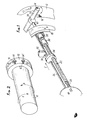
- the limit switch system object of this invention comprises: a crown with internal toothing, driven by the shaft on which the shutter or blind is wound, which meshes on a idler rotating pinion on a screw parallel to the axis said winding shaft; a clutch secured to said screw which, by translational movement of the screw, can be secured to the idler rotating pinion; a clutch button comprising a cam making it possible to act in translation on said screw and a locating index; a cursor mounted on said screw immobilized in rotation and able to come into contact with the microswitch button of the gearmotor control system to cause the latter to stop, giving rise to the high or low limit switch, depending on the direction of winding of the shutter or of the awning.
- said screw is pushed back using a spring when it is released in translation by said cam, during the operation of said control button, the clutch, which is preferably of the dog type, then engaging the idler rotating gear.
- the system comprises (FIG. 1) an internal gear ring 18 which is driven, for example in the direction of arrow A, by the shaft on which the roller shutter is wound.
- This ring 18 is engaged with a pinion 20 which is mounted idly on a smooth part of an endless screw 22.
- On this endless screw 22 is mounted a slider 24, immobilized in rotation using a fixed rod 26, parallel to the screw 22.
- the screw endless 22 has a thread in one direction such that the slider 24, immobilized in rotation as indicated in the drawing, can move along the screw 22 according to the arrow "f" when the winding shaft of the shutter, and therefore the crown 18, rotate according to arrow A.
- the screw 22 is pushed back by a resort 28, provided at its end opposite to the crown 18, and, at its other end, a clutch is inserted, preferably of the dog clutch type 30, between the pinion 20 and the screw, this clutch being secured to the screw 22.
- a micro-contact 32 acting on the power supply of the geared motor assembly (not shown) for controlling the rotation of the shaft of the rolling shutter, and therefore of the crown 18, this micro -contact comprising a button 34, actuated, as will be seen below, by pressing the cursor 24.
- Each control button such as 14, is carried by a rod 36, provided with a cam 38 bearing on the end 40.
- the end positions are marked at the factory.
- the button 14 By rotation of the button 14, so as to make the index which it carries coincide with the index 16, provided on the outer case 12, the rod 36 and the cam 38 are rotated, the latter releasing the screw 22 in translation , which is pushed back by the spring 28 in the direction of the arrow "f".
- the direction of the thread of the screw 22 is such that the slider 24, immobilized in rotation by the rod 26, moves along this rod in the direction of the arrow "f", when the winding shaft of the shutter and the pinion 20 rotate according to the arrow A.
- the button 14 After carrying out this operation of locating an end of travel, the button 14 is acted on, so as to bring into opposition the index carried by this button and the corresponding index 16 carried by the housing 12.
- the rotation of the button 14, therefore of the rod 36 drives the cam 38 which pushes the screw 22.
- the clutch clutch 30 disengages from the pinion 20.
- the cursor 24 moves along the rod 26 in the opposite direction to that indicated by the arrow "f", thus releasing the button 34 of the micro-contact 32, which authorizes the operation of the gear motor, the limit switch being neutralized with regard to one of the directions of rotation of the winding shaft.
- a second system identical to that described above, different only in the thread direction of the screw 22, makes it possible to mark the end of travel of the second direction of rotation of the winding shaft according to the same operating mode .
- the change-over control switch will make it possible to carry out the tests of ascent or descent and to locate each of the two extreme operating positions, and without automatic end-of-travel stop.
- To obtain the automatic stop it is sufficient, after having identified the operating directions with respect to the arrows (a) and (b), on the housing 12, to bring on the button 14, 14 ⁇ corresponding the indexes 16 and 16 ⁇ in coincidence.
Landscapes
- Engineering & Computer Science (AREA)
- Structural Engineering (AREA)
- Architecture (AREA)
- Civil Engineering (AREA)
- Operating, Guiding And Securing Of Roll- Type Closing Members (AREA)
Applications Claiming Priority (2)
| Application Number | Priority Date | Filing Date | Title |
|---|---|---|---|
| FR8703496A FR2612245A1 (fr) | 1987-03-13 | 1987-03-13 | Systeme interrupteur de fin de course pour motoreducteur, notamment pour volet roulant |
| FR8703496 | 1987-03-13 |
Publications (1)
| Publication Number | Publication Date |
|---|---|
| EP0282401A2 true EP0282401A2 (de) | 1988-09-14 |
Family
ID=9348959
Family Applications (1)
| Application Number | Title | Priority Date | Filing Date |
|---|---|---|---|
| EP19880400491 Withdrawn EP0282401A2 (de) | 1987-03-13 | 1988-03-02 | Endschalter-System für Getriebsmotoren, insbesondere für Rolläden |
Country Status (2)
| Country | Link |
|---|---|
| EP (1) | EP0282401A2 (de) |
| FR (1) | FR2612245A1 (de) |
Cited By (2)
| Publication number | Priority date | Publication date | Assignee | Title |
|---|---|---|---|---|
| US6289964B1 (en) | 1997-04-02 | 2001-09-18 | Hunter Douglas Inc. | Control and suspension system for a covering for architectural openings |
| US6435252B2 (en) | 1998-06-22 | 2002-08-20 | Hunter Douglas Inc. | Control and suspension system for a covering for architectural openings |
Families Citing this family (1)
| Publication number | Priority date | Publication date | Assignee | Title |
|---|---|---|---|---|
| AU2016222259B2 (en) * | 2015-02-19 | 2020-07-09 | Rollease Acmeda Pty Ltd | Limiter assembly for a blind |
Family Cites Families (3)
| Publication number | Priority date | Publication date | Assignee | Title |
|---|---|---|---|---|
| FR2412483A1 (fr) * | 1977-12-20 | 1979-07-20 | Simu Soc Ind Metal Usine | Dispositif de debrayage et de reglage instantane des fins de course d'un enrouleur automatique |
| FR2459775A2 (fr) * | 1979-06-27 | 1981-01-16 | Simu Soc Ind Metal Usine | Dispositif de debrayage et de reglage instantane des fins de course d'un enrouleur automatique |
| FR2459776A2 (fr) * | 1979-06-27 | 1981-01-16 | Simu Soc Ind Metal Usine | Dispositif de debrayage et de reglage instantane des fins de course d'un enrouleur automatique |
-
1987
- 1987-03-13 FR FR8703496A patent/FR2612245A1/fr active Pending
-
1988
- 1988-03-02 EP EP19880400491 patent/EP0282401A2/de not_active Withdrawn
Cited By (3)
| Publication number | Priority date | Publication date | Assignee | Title |
|---|---|---|---|---|
| US6289964B1 (en) | 1997-04-02 | 2001-09-18 | Hunter Douglas Inc. | Control and suspension system for a covering for architectural openings |
| US6435252B2 (en) | 1998-06-22 | 2002-08-20 | Hunter Douglas Inc. | Control and suspension system for a covering for architectural openings |
| US6782938B2 (en) | 1998-06-22 | 2004-08-31 | Hunter Douglas Inc. | Control and suspension system for a covering for architectural openings |
Also Published As
| Publication number | Publication date |
|---|---|
| FR2612245A1 (fr) | 1988-09-16 |
Similar Documents
| Publication | Publication Date | Title |
|---|---|---|
| FR2614962A1 (fr) | Transmission, notamment pour winch ou boite de vitesse | |
| CH634896A5 (fr) | Dispositif de commande pour moto-reducteur electrique. | |
| EP0282401A2 (de) | Endschalter-System für Getriebsmotoren, insbesondere für Rolläden | |
| JPS61286678A (ja) | バルブのスピンドル駆動機構 | |
| FR2527341A1 (fr) | Commande pour la mise au point d'un microscope | |
| FR2466297A1 (fr) | Contre-poupee pour machines-outils, en particulier tours ou machines similaires, avec organe d'actionnement electrique a poussee controlee | |
| EP0524152B1 (de) | Automatische Abstellvorrichtung mit Schaltmuffe für elektrischen Motor | |
| AU616046B2 (en) | Venetian blind lifting and tilting mechanism | |
| FR2850151A1 (fr) | Dispositif de commande de boite de vitesses manuelle pilotee a manchon rotatif et methode de changement de rapport assoc iee | |
| FR2459776A2 (fr) | Dispositif de debrayage et de reglage instantane des fins de course d'un enrouleur automatique | |
| JPH0510158Y2 (de) | ||
| EP0844363B1 (de) | Antriebsvorrichtung für Rolladen oder dergleichen | |
| JP2514189Y2 (ja) | 電動式シャッタ―の開閉装置 | |
| FR3087474A1 (fr) | Procede de controle d'un systeme d'actionnement d'un premier et d'un second ecrans et systeme d'actionnement | |
| KR20210029998A (ko) | 비닐하우스용 전동개폐기 | |
| JPS6040985Y2 (ja) | テ−プレコ−ダにおけるテ−プ送行装置 | |
| FR2765165A1 (fr) | Dispositif correcteur de l'orientation du faisceau lumineux emis par un projecteur de vehicule automobile | |
| JPS6134497Y2 (de) | ||
| FR2588308A1 (fr) | Dispositif de fins de course pour la commande automatique des stores, volets roulants ou autres appareils de levage a tambour tournant | |
| JP2859074B2 (ja) | スイッチ機構の基準位置設定装置および基準位置設定方法 | |
| EP0320388B1 (de) | Aufwickelvorrichtung für Bündel von in Lagen angeordneten Verbinderdrähten | |
| FR2624194A1 (fr) | Perfectionnement aux dispositifs de fin de course pour motoreducteurs de volets roulants | |
| EP0326501B1 (de) | Vorrichtung und Verfahren zum Positionieren eines Werkzeughalters entlang einer Achse | |
| JPH073894Y2 (ja) | 魚釣リールのドラグ機構 | |
| JP2536306Y2 (ja) | チューブラモータの制御装置 |
Legal Events
| Date | Code | Title | Description |
|---|---|---|---|
| PUAI | Public reference made under article 153(3) epc to a published international application that has entered the european phase |
Free format text: ORIGINAL CODE: 0009012 |
|
| AK | Designated contracting states |
Kind code of ref document: A2 Designated state(s): BE DE ES GB IT LU NL |
|
| STAA | Information on the status of an ep patent application or granted ep patent |
Free format text: STATUS: THE APPLICATION HAS BEEN WITHDRAWN |
|
| 18W | Application withdrawn |
Withdrawal date: 19881215 |