EP0282401A2 - Limit switch system for gear motors, in particular for roller shutters - Google Patents
Limit switch system for gear motors, in particular for roller shutters Download PDFInfo
- Publication number
- EP0282401A2 EP0282401A2 EP19880400491 EP88400491A EP0282401A2 EP 0282401 A2 EP0282401 A2 EP 0282401A2 EP 19880400491 EP19880400491 EP 19880400491 EP 88400491 A EP88400491 A EP 88400491A EP 0282401 A2 EP0282401 A2 EP 0282401A2
- Authority
- EP
- European Patent Office
- Prior art keywords
- screw
- button
- clutch
- limit switch
- shutter
- Prior art date
- Legal status (The legal status is an assumption and is not a legal conclusion. Google has not performed a legal analysis and makes no representation as to the accuracy of the status listed.)
- Withdrawn
Links
Images
Classifications
-
- E—FIXED CONSTRUCTIONS
- E06—DOORS, WINDOWS, SHUTTERS, OR ROLLER BLINDS IN GENERAL; LADDERS
- E06B—FIXED OR MOVABLE CLOSURES FOR OPENINGS IN BUILDINGS, VEHICLES, FENCES OR LIKE ENCLOSURES IN GENERAL, e.g. DOORS, WINDOWS, BLINDS, GATES
- E06B9/00—Screening or protective devices for wall or similar openings, with or without operating or securing mechanisms; Closures of similar construction
- E06B9/56—Operating, guiding or securing devices or arrangements for roll-type closures; Spring drums; Tape drums; Counterweighting arrangements therefor
- E06B9/80—Safety measures against dropping or unauthorised opening; Braking or immobilising devices; Devices for limiting unrolling
- E06B9/82—Safety measures against dropping or unauthorised opening; Braking or immobilising devices; Devices for limiting unrolling automatic
- E06B9/88—Safety measures against dropping or unauthorised opening; Braking or immobilising devices; Devices for limiting unrolling automatic for limiting unrolling
-
- E—FIXED CONSTRUCTIONS
- E06—DOORS, WINDOWS, SHUTTERS, OR ROLLER BLINDS IN GENERAL; LADDERS
- E06B—FIXED OR MOVABLE CLOSURES FOR OPENINGS IN BUILDINGS, VEHICLES, FENCES OR LIKE ENCLOSURES IN GENERAL, e.g. DOORS, WINDOWS, BLINDS, GATES
- E06B9/00—Screening or protective devices for wall or similar openings, with or without operating or securing mechanisms; Closures of similar construction
- E06B9/56—Operating, guiding or securing devices or arrangements for roll-type closures; Spring drums; Tape drums; Counterweighting arrangements therefor
- E06B9/68—Operating devices or mechanisms, e.g. with electric drive
- E06B2009/6809—Control
- E06B2009/6872—Control using counters to determine shutter position
- E06B2009/6881—Mechanical counters
Definitions
- the present invention relates to a limit switch system for a gear motor, in particular for the operation of roller shutters, blinds and the like.
- the electrical control devices for operating roller shutters, blinds and the like generally comprise limit switches designed so as to allow the operation of the drive gear motor to stop, respectively in the lower limit position ( shutter closed or blind lowered) and in the upper end position (open shutter or blind raised).
- This invention therefore relates to such a system, which is designed in particular so as to allow precise positioning of the limit switches without adjustment.
- the limit switch system object of this invention comprises: a crown with internal toothing, driven by the shaft on which the shutter or blind is wound, which meshes on a idler rotating pinion on a screw parallel to the axis said winding shaft; a clutch secured to said screw which, by translational movement of the screw, can be secured to the idler rotating pinion; a clutch button comprising a cam making it possible to act in translation on said screw and a locating index; a cursor mounted on said screw immobilized in rotation and able to come into contact with the microswitch button of the gearmotor control system to cause the latter to stop, giving rise to the high or low limit switch, depending on the direction of winding of the shutter or of the awning.
- said screw is pushed back using a spring when it is released in translation by said cam, during the operation of said control button, the clutch, which is preferably of the dog type, then engaging the idler rotating gear.
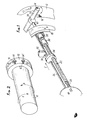
- the system comprises (FIG. 1) an internal gear ring 18 which is driven, for example in the direction of arrow A, by the shaft on which the roller shutter is wound.
- This ring 18 is engaged with a pinion 20 which is mounted idly on a smooth part of an endless screw 22.
- On this endless screw 22 is mounted a slider 24, immobilized in rotation using a fixed rod 26, parallel to the screw 22.
- the screw endless 22 has a thread in one direction such that the slider 24, immobilized in rotation as indicated in the drawing, can move along the screw 22 according to the arrow "f" when the winding shaft of the shutter, and therefore the crown 18, rotate according to arrow A.
- the screw 22 is pushed back by a resort 28, provided at its end opposite to the crown 18, and, at its other end, a clutch is inserted, preferably of the dog clutch type 30, between the pinion 20 and the screw, this clutch being secured to the screw 22.
- a micro-contact 32 acting on the power supply of the geared motor assembly (not shown) for controlling the rotation of the shaft of the rolling shutter, and therefore of the crown 18, this micro -contact comprising a button 34, actuated, as will be seen below, by pressing the cursor 24.
- Each control button such as 14, is carried by a rod 36, provided with a cam 38 bearing on the end 40.
- the end positions are marked at the factory.
- the button 14 By rotation of the button 14, so as to make the index which it carries coincide with the index 16, provided on the outer case 12, the rod 36 and the cam 38 are rotated, the latter releasing the screw 22 in translation , which is pushed back by the spring 28 in the direction of the arrow "f".
- the direction of the thread of the screw 22 is such that the slider 24, immobilized in rotation by the rod 26, moves along this rod in the direction of the arrow "f", when the winding shaft of the shutter and the pinion 20 rotate according to the arrow A.
- the button 14 After carrying out this operation of locating an end of travel, the button 14 is acted on, so as to bring into opposition the index carried by this button and the corresponding index 16 carried by the housing 12.
- the rotation of the button 14, therefore of the rod 36 drives the cam 38 which pushes the screw 22.
- the clutch clutch 30 disengages from the pinion 20.
- the cursor 24 moves along the rod 26 in the opposite direction to that indicated by the arrow "f", thus releasing the button 34 of the micro-contact 32, which authorizes the operation of the gear motor, the limit switch being neutralized with regard to one of the directions of rotation of the winding shaft.
- a second system identical to that described above, different only in the thread direction of the screw 22, makes it possible to mark the end of travel of the second direction of rotation of the winding shaft according to the same operating mode .
- the change-over control switch will make it possible to carry out the tests of ascent or descent and to locate each of the two extreme operating positions, and without automatic end-of-travel stop.
- To obtain the automatic stop it is sufficient, after having identified the operating directions with respect to the arrows (a) and (b), on the housing 12, to bring on the button 14, 14 ⁇ corresponding the indexes 16 and 16 ⁇ in coincidence.
Abstract
Description
La présente invention est relative à un système interrupteur de fin de course pour moto-réducteur, notamment pour la manoeuvre de volets roulants, stores et similaires.The present invention relates to a limit switch system for a gear motor, in particular for the operation of roller shutters, blinds and the like.
Les dispositifs de commande électrique de manoeuvre des volets roulants, stores et similaires, comportent généralement des interrupteurs de fin de course conçus de façon à permettre l'arrêt du fonctionnement du moto-réducteur d'entraînement, respectivement en position de fin de course basse (volet fermé ou store baissé) et en position de fin de course haute (volet ouvert ou store levé).The electrical control devices for operating roller shutters, blinds and the like, generally comprise limit switches designed so as to allow the operation of the drive gear motor to stop, respectively in the lower limit position ( shutter closed or blind lowered) and in the upper end position (open shutter or blind raised).
Cette invention a donc pour objet un tel système, qui est conçu notamment de manière à permettre un positionnement précis des fins de course sans réglage.This invention therefore relates to such a system, which is designed in particular so as to allow precise positioning of the limit switches without adjustment.
Le système interrupteur de fin de course objet de cette invention comprend : une couronne à denture intérieure, entraînée par l'arbre sur lequel s'enroule le volet ou le store, qui engrène sur un pignon tournant fou sur une vis parallèle à l'axe dudit arbre d'enroulement ; un embrayage solidaire de ladite vis pouvant, par déplacement en translation de la vis, être solidarisé avec le pignon tournant fou ; un bouton d'embrayage comportant une came permettant d'agir en translation sur ladite vis et un index de repérage ; un curseur monté sur ladite vis immobilisé en rotation et pouvant venir en appui sur le bouton du microcontact du système de commande du moto-réducteur pour provoquer l'arrêt de ce dernier, concrétisant la fin de course haute ou basse, selon le sens de l'enroulement du volet ou du store.The limit switch system object of this invention comprises: a crown with internal toothing, driven by the shaft on which the shutter or blind is wound, which meshes on a idler rotating pinion on a screw parallel to the axis said winding shaft; a clutch secured to said screw which, by translational movement of the screw, can be secured to the idler rotating pinion; a clutch button comprising a cam making it possible to act in translation on said screw and a locating index; a cursor mounted on said screw immobilized in rotation and able to come into contact with the microswitch button of the gearmotor control system to cause the latter to stop, giving rise to the high or low limit switch, depending on the direction of winding of the shutter or of the awning.
Selon une caractéristique de cette invention, ladite vis est repoussée à l'aide d'un ressort lorsqu'elle est libérée en translation par ladite came, lors de la manoeuvre dudit bouton de commande, l'embrayage, qui, de préférence, est du type à crabots, venant alors en prise avec le pignon tournant fou.According to a characteristic of this invention, said screw is pushed back using a spring when it is released in translation by said cam, during the operation of said control button, the clutch, which is preferably of the dog type, then engaging the idler rotating gear.
D'autres caractéristiques et avantages de cette invention ressortiront de la description faite ci-après en référence au dessin annexé, sur lequel :
- - la Figure 1 est une vue en perspective montrant le mécanisme du système objet de cette invention ; et,
- - la Figure 2 est une vue en perspective du système.
- - Figure 1 is a perspective view showing the mechanism of the system object of this invention; and,
- - Figure 2 is a perspective view of the system.
En se référant au dessin, on voit que le système objet de l'invention s'applique ici à un arbre 10 sur lequel s'enroule un volet roulant ou un store. Sur la Figure 2, on a indiqué par une flèche A le sens montée ou descente qui correspond à la flèche "a" portée sur le boîtier 12 du système, en bout d'arbre. De même, la flèche B correspond à la flèche "b" portée sur le boîtier. Sur ce dernier, on prévoit des boutons de commande 14, 14ʹ, pouvant être amenés par rotation (comme on le décrira ci-après) en regard d'index de repérage 16, 16ʹ, respectivement, pour interrompre ou permettre le mouvement indiqué par ces flèches.Referring to the drawing, it can be seen that the system which is the subject of the invention applies here to a
Le système comprend (Figure 1) une couronne à denture intérieure 18 qui est entraînée, par exemple dans le sens de la flèche A, par l'arbre sur lequel s'enroule le volet roulant. Cette couronne 18 est en prise avec un pignon 20 qui est monté fou sur une partie lisse d'une vis sans fin 22. Sur cette vis sans fin 22 est monté un curseur 24, immobilisé en rotation à l'aide d'une tige fixe 26, parallèle à la vis 22. La vis sans fin 22 possède un filetage dans un sens tel que le curseur 24, immobilisé en rotation comme indiqué sur le dessin, peut se déplacer le long de la vis 22 selon la flèche "f" lorsque l'arbre d'enroulement du volet, et donc la couronne 18, tournent selon la flèche A.The system comprises (FIG. 1) an
La vis 22 est repoussée par un resort 28, prévu à son extrémité opposée à la couronne 18, et, à son autre extrémité, on intercale un embrayage, de préférence de type à crabots 30, entre le pignon 20 et la vis, cet embrayage étant rendu solidaire de la vis 22.The
En regard du curseur 24 est disposé un micro-contact 32 agissant sur l'alimentation de l'ensemble moto-réducteur (non représenté) de commande de la rotation de l'arbre du volet roulant, et donc de la couronne 18, ce micro-contact comportant un bouton 34, actionné, comme on le verra ci-après, par la pression du curseur 24.Opposite the
Chaque bouton de commande, tel que 14, est porté par une tige 36, munie d'une came 38 prenant appui sur l'extrémité 40.Each control button, such as 14, is carried by a
On décrira maintenant le fonctionnement de ce système.The operation of this system will now be described.
On réalise en usine le repérage des positions de fin de course.The end positions are marked at the factory.
Par rotation du bouton 14, de manière à faire coïncider l'index qu'il porte avec l'index 16, prévu sur le boîtier extérieur 12, on fait tourner la tige 36 et la came 38, cette dernière libérant en translation la vis 22, qui est repoussée par le ressort 28 selon le sens de la flèche "f". L'embrayage à crabots 30, solidaire de la vis 22, vient en prise avec le pignon 20. Comme on l'a précisé ci-dessus, le sens du filetage de la vis 22 est tel que le curseur 24, immobilisé en rotation par la tige 26, se déplace le long de cette tige dans le sens de la flèche "f", lorsque l'arbre d'enroulement du volet et le pignon 20 tournent selon la flèche A.By rotation of the
A l'issue de son déplacement en translation le long de la tige 26, le curseur 24 vient prendre appui sur le bouton 34 du micro-contact 32, provoquant ainsi l'arrêt du motoréducteur entraînant l'arbre d'enroulement. Cet arrêt concrétise une position de fin de course haute ou basse, suivant le sens de l'enroulement du volet.At the end of its translational movement along the
Après exécution de cette opération de repérage d'une fin de course, on agit sur le bouton 14, de manière à amener en opposition l'index porté par ce bouton et l'index correspondant 16, porté par le boîtier 12. La rotation du bouton 14, donc de la tige 36, entraîne la came 38 qui repousse la vis 22. Simultanément, l'embrayage à crabots 30 se désolidarise du pignon 20. Le curseur 24 se déplace le long de la tige 26 dans le sens inverse de celui indiqué par la flèche "f", libérant ainsi le bouton 34 du micro-contact 32, ce qui autorise le fonctionnement du moto-réducteur, l'interrupteur de fin de course étant neutralisé pour ce qui concerne l'un des sens de rotation de l'arbre d'enroulement.After carrying out this operation of locating an end of travel, the
Un second système, identique à celui décrit ci-dessus, différent uniquement par le sens de filetage de la vis 22, permet de réaliser le repérage de fin de course du second sens de rotation de l'arbre d'enroulement selon le même mode opératoire.A second system, identical to that described above, different only in the thread direction of the
L'ensemble arbre-volet roulant ou store étant mis en place et les raccordements électriques adéquats étant effectués, l'interrupteur inverseur de commande permettra d'effectuer les tests de montée ou de descente et de situer chacune des deux positions extrêmes de fonctionnement, et cela sans arrêt automatique de fin de course. Pour obtenir l'arrêt automatique, il suffit, après avoir repéré les sens de fonctionnement par rapport aux flèches (a) et (b), sur le boîtier 12, d'amener sur le bouton 14, 14ʹ correspondant les index 16 et 16ʹ en coïncidence.The shaft-roller shutter or blind assembly being put in place and the adequate electrical connections being made, the change-over control switch will make it possible to carry out the tests of ascent or descent and to locate each of the two extreme operating positions, and without automatic end-of-travel stop. To obtain the automatic stop, it is sufficient, after having identified the operating directions with respect to the arrows (a) and (b), on the
En cas de fausse manoeuvre dans l'opération effectuée sur les boutons, il est toujours possible de faire une correction. Pour cela, il suffit d'amener le système en coupure automatique dans un sens ou dans l'autre et de débrayer en agissant sur le bouton correspondant, de façon à ce que les index correspondants, portés respectivement par le bouton et le boîtier, soient en opposition, puis de rectifier en commande, sans coupure automatique, de manière à amener le volet ou le store dans la nouvelle position souhaitée, et enfin de rembrayer la coupure automatique en mettant les index en coïncidence.In the event of a false operation in the operation carried out on the buttons, it is always possible to make a correction. For this, it suffices to bring the system to automatic cut in one direction or the other and to disengage by acting on the corresponding button, so that the corresponding indexes, carried respectively by the button and the case, are in opposition, then to rectify on command, without automatic cut, so as to bring the shutter or the blind to the new desired position, and finally to repay the automatic cut by putting the indexes in coincidence.
Il demeure bien entendu que cette invention n'est pas limitée aux exemples de réalisation décrits et représentés, mais qu'elle en englobe toutes les variantes.It remains to be understood that this invention is not limited to the embodiments described and shown, but that it encompasses all variants thereof.
Claims (3)
Applications Claiming Priority (2)
| Application Number | Priority Date | Filing Date | Title |
|---|---|---|---|
| FR8703496A FR2612245A1 (en) | 1987-03-13 | 1987-03-13 | LIMIT SWITCH SYSTEM FOR MOTOR REDUCER, PARTICULARLY FOR ROLLER SHUTTER |
| FR8703496 | 1987-03-13 |
Publications (1)
| Publication Number | Publication Date |
|---|---|
| EP0282401A2 true EP0282401A2 (en) | 1988-09-14 |
Family
ID=9348959
Family Applications (1)
| Application Number | Title | Priority Date | Filing Date |
|---|---|---|---|
| EP19880400491 Withdrawn EP0282401A2 (en) | 1987-03-13 | 1988-03-02 | Limit switch system for gear motors, in particular for roller shutters |
Country Status (2)
| Country | Link |
|---|---|
| EP (1) | EP0282401A2 (en) |
| FR (1) | FR2612245A1 (en) |
Cited By (2)
| Publication number | Priority date | Publication date | Assignee | Title |
|---|---|---|---|---|
| US6289964B1 (en) | 1997-04-02 | 2001-09-18 | Hunter Douglas Inc. | Control and suspension system for a covering for architectural openings |
| US6435252B2 (en) | 1998-06-22 | 2002-08-20 | Hunter Douglas Inc. | Control and suspension system for a covering for architectural openings |
Families Citing this family (1)
| Publication number | Priority date | Publication date | Assignee | Title |
|---|---|---|---|---|
| WO2016131081A1 (en) * | 2015-02-19 | 2016-08-25 | Rollease Acmeda Pty Ltd | Limiter assembly for a blind |
Family Cites Families (3)
| Publication number | Priority date | Publication date | Assignee | Title |
|---|---|---|---|---|
| FR2412483A1 (en) * | 1977-12-20 | 1979-07-20 | Simu Soc Ind Metal Usine | Automatic winding machine disengagement adjustment - has screws of opposite pitch in winding tube and with disengaging pinions |
| FR2459776A2 (en) * | 1979-06-27 | 1981-01-16 | Simu Soc Ind Metal Usine | Roller blind winding gear - has declutching gear for drive rods operated by cam to push rods into engagement |
| FR2459775A2 (en) * | 1979-06-27 | 1981-01-16 | Simu Soc Ind Metal Usine | Roller blind winding gear - has automatic de-clutching gear with central cam operated from control lever |
-
1987
- 1987-03-13 FR FR8703496A patent/FR2612245A1/en active Pending
-
1988
- 1988-03-02 EP EP19880400491 patent/EP0282401A2/en not_active Withdrawn
Cited By (3)
| Publication number | Priority date | Publication date | Assignee | Title |
|---|---|---|---|---|
| US6289964B1 (en) | 1997-04-02 | 2001-09-18 | Hunter Douglas Inc. | Control and suspension system for a covering for architectural openings |
| US6435252B2 (en) | 1998-06-22 | 2002-08-20 | Hunter Douglas Inc. | Control and suspension system for a covering for architectural openings |
| US6782938B2 (en) | 1998-06-22 | 2004-08-31 | Hunter Douglas Inc. | Control and suspension system for a covering for architectural openings |
Also Published As
| Publication number | Publication date |
|---|---|
| FR2612245A1 (en) | 1988-09-16 |
Similar Documents
| Publication | Publication Date | Title |
|---|---|---|
| US5448837A (en) | Structure of measuring tape | |
| FR2614962A1 (en) | TRANSMISSION, IN PARTICULAR FOR WINCH OR SPEED BOX | |
| CH634896A5 (en) | CONTROL DEVICE FOR ELECTRIC MOTOR-REDUCER. | |
| US5044089A (en) | Power-operated measuring tape | |
| EP3106598A1 (en) | System for driving an openable body section | |
| EP0282401A2 (en) | Limit switch system for gear motors, in particular for roller shutters | |
| FR2527341A1 (en) | CONTROL FOR THE DEVELOPMENT OF A MICROSCOPE | |
| FR2466297A1 (en) | DOLL COUNTER FOR MACHINE TOOLS, ESPECIALLY TOWERS OR SIMILAR MACHINES, WITH CONTROLLED PUSHED ELECTRIC ACTUATION DEVICE | |
| JPS61286678A (en) | Spindle driving mechanism of valve | |
| AU616046B2 (en) | Venetian blind lifting and tilting mechanism | |
| EP0524152B1 (en) | Automatic stop device with actuating sleeve for electric motor | |
| FR2850151A1 (en) | Motor vehicle transmission selector has shaft moved by solenoid to rotate sleeve with ration change finger | |
| FR2459776A2 (en) | Roller blind winding gear - has declutching gear for drive rods operated by cam to push rods into engagement | |
| JPH0510158Y2 (en) | ||
| EP0844363B1 (en) | Driving device for roller shutter or the like | |
| JP2514189Y2 (en) | Opening / closing device for electric shutter | |
| FR2493906A1 (en) | ROLLER SHUTTER OR SIMILAR DEVICE WITH ELECTRIC DRIVE AND AUTOMATIC CONTROL | |
| FR2765165A1 (en) | CORRECTION DEVICE FOR THE ORIENTATION OF THE LIGHT BEAM EMITTED BY A MOTOR VEHICLE PROJECTOR | |
| JPS6134497Y2 (en) | ||
| JP2859074B2 (en) | Reference position setting device and reference position setting method for switch mechanism | |
| EP0320388B1 (en) | Reel for bundles of connector wires disposed in layers | |
| FR2624194A1 (en) | Improvement to end-of-travel devices for reduction motors for roller shutters | |
| FR2588308A1 (en) | END-LIMIT DEVICE FOR AUTOMATICALLY CONTROLLING BLINDS, SHUTTERS OR OTHER ROTATING DRUM LIFTING DEVICES | |
| JPH073894Y2 (en) | Drag mechanism of fishing reel | |
| JP2536306Y2 (en) | Control device for tubular motor |
Legal Events
| Date | Code | Title | Description |
|---|---|---|---|
| PUAI | Public reference made under article 153(3) epc to a published international application that has entered the european phase |
Free format text: ORIGINAL CODE: 0009012 |
|
| AK | Designated contracting states |
Kind code of ref document: A2 Designated state(s): BE DE ES GB IT LU NL |
|
| STAA | Information on the status of an ep patent application or granted ep patent |
Free format text: STATUS: THE APPLICATION HAS BEEN WITHDRAWN |
|
| 18W | Application withdrawn |
Withdrawal date: 19881215 |