EP0281518B1 - Vermessungsinstrument - Google Patents
Vermessungsinstrument Download PDFInfo
- Publication number
- EP0281518B1 EP0281518B1 EP88810109A EP88810109A EP0281518B1 EP 0281518 B1 EP0281518 B1 EP 0281518B1 EP 88810109 A EP88810109 A EP 88810109A EP 88810109 A EP88810109 A EP 88810109A EP 0281518 B1 EP0281518 B1 EP 0281518B1
- Authority
- EP
- European Patent Office
- Prior art keywords
- reference mark
- instrument
- image
- optical
- camera
- Prior art date
- Legal status (The legal status is an assumption and is not a legal conclusion. Google has not performed a legal analysis and makes no representation as to the accuracy of the status listed.)
- Expired - Lifetime
Links
- 230000003287 optical effect Effects 0.000 claims description 31
- 238000003384 imaging method Methods 0.000 claims description 3
- 238000001514 detection method Methods 0.000 claims 1
- 230000005855 radiation Effects 0.000 description 9
- 238000005259 measurement Methods 0.000 description 4
- 230000005484 gravity Effects 0.000 description 3
- 230000000694 effects Effects 0.000 description 2
- 230000000295 complement effect Effects 0.000 description 1
- 230000008878 coupling Effects 0.000 description 1
- 238000010168 coupling process Methods 0.000 description 1
- 238000005859 coupling reaction Methods 0.000 description 1
- 230000001419 dependent effect Effects 0.000 description 1
- 229910003460 diamond Inorganic materials 0.000 description 1
- 239000010432 diamond Substances 0.000 description 1
- 238000011156 evaluation Methods 0.000 description 1
- 239000011521 glass Substances 0.000 description 1
- 238000000034 method Methods 0.000 description 1
Images

Classifications
-
- G—PHYSICS
- G01—MEASURING; TESTING
- G01C—MEASURING DISTANCES, LEVELS OR BEARINGS; SURVEYING; NAVIGATION; GYROSCOPIC INSTRUMENTS; PHOTOGRAMMETRY OR VIDEOGRAMMETRY
- G01C15/00—Surveying instruments or accessories not provided for in groups G01C1/00 - G01C13/00
-
- G—PHYSICS
- G01—MEASURING; TESTING
- G01C—MEASURING DISTANCES, LEVELS OR BEARINGS; SURVEYING; NAVIGATION; GYROSCOPIC INSTRUMENTS; PHOTOGRAMMETRY OR VIDEOGRAMMETRY
- G01C1/00—Measuring angles
- G01C1/02—Theodolites
-
- G—PHYSICS
- G01—MEASURING; TESTING
- G01C—MEASURING DISTANCES, LEVELS OR BEARINGS; SURVEYING; NAVIGATION; GYROSCOPIC INSTRUMENTS; PHOTOGRAMMETRY OR VIDEOGRAMMETRY
- G01C1/00—Measuring angles
- G01C1/02—Theodolites
- G01C1/04—Theodolites combined with cameras
Definitions
- the present invention relates to a measuring instrument with an optical instrument part for imaging a target and an image field, with a lens, with a camera for electronically capturing the image generated in the instrument part and with a reference mark, the image of the target and that of the reference mark in the camera be mapped.
- a telescopic sight serves as an optical component of such an instrument.
- a camera is assigned to the telescope, the image of the crosshair and the target, the target figure or the target mark captured by the telescope being displayed on a screen.
- the riflescope can be adjusted in such a way that the middle part of the image of the target and the middle part of the crosshairs overlap.
- the measured values can only be obtained by the operator adjusting the optical part thereof. In some applications of surveying instruments, however, it is required that the measured values are recorded automatically.
- US Pat. No. 3,227,035 describes a measuring instrument with a camera, an optical instrument system and a reference mark. An object image is projected into the camera via the optical system and overlaid with the image of a reference mark. The object image is hidden in the area of the reference mark with two complementary filters. With this arrangement, important information is therefore lost when it is hidden. A circuit for determining the position of the image centers of the reference mark and target is not disclosed in this document.
- an optical measuring device with a measuring mark arranged in the beam path is known.
- the measuring mark is formed from a mirrored glass surface, which is arranged at 45 ° in the beam path of the instrument. This measurement mark can be illuminated by a light source, so that the mark appears in the eyepiece as either a light or dark mark.
- the device described in this document has neither a camera nor an electronic evaluation device for determining the image centers of the reference mark and target object. The device is used to manually center the respective objects in or on the measuring marks.
- the object of the present invention is to provide a measuring instrument which enables measurements to be carried out automatically.
- Embodiments of the invention are the subject of dependent claims 2 to 9.
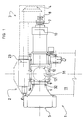
- the present measuring instrument has an optical component 1 and a camera 2.
- the optical instrument part 1 is used to image a target or a target mark (not shown), which are located in the target area, for example in a terrain to be measured, inside a building or the like, and which mark the respective location of the object to be measured.
- a measurement mark known per se can be used as such a mark.
- the camera 2 has an optical entry part 23, in which there is an array of optoelectric elements. These are used to convert optical images into electrical signals. Such cameras are also already known.
- the coupling between the exit part of the optical instrument part 1 and the optical entry part 23 of the camera 2 takes place with the aid of an optical deflection device 3, which is connected between these two instrument parts 1 and 2.
- This deflection device 3 contains, in addition to other parts, e.g. an imaging optics 8, also a prism 4, which effects the required deflection of the optical beams to the camera 2.
- the optical part 1 has a lens 5, which is located in the beginning of a housing 6.
- an eyepiece 7 In the opposite end part of this housing 6 there is an eyepiece 7 to which the deflection device 3 is assigned.
- an aperture 10 which bears a reference mark (20, FIG. 2 and the following). This means that both the image of the target and the reference mark are visible at the same time.
- the eyepiece 7 is arranged with respect to this plane in such a way that this plane is located in the front focal plane of the eyepiece 7. The image of the target and the image of the reference mark can thus be viewed simultaneously through the eyepiece 7 to be watched.
- the tilt axis 12 consists of two shaft halves 121, of which only the shaft half 121 mounted in the rear support side 11 is indicated in FIG. 1.
- the ends of the shaft halves 121 facing away from the bearing points are fastened to the side surfaces of a sleeve 31, which thus forms a unit rotatable about the tilt axis with these shaft halves 121.
- the camera 2 is located on a support plate 13 which is fastened on the top of the sleeve 31 with the aid of screws 14.
- the inner diameter of said sleeve 31 is larger than the outer diameter of the middle part of the telescope housing 6.
- This middle part of the housing 6, which is cylindrical, is provided with a holding plate 9 which is perpendicular to the longitudinal axis of the housing 6. Bores are made in the corners of this holding plate 9, through which fastening screws 32 for the telescope 1 pass. These screws 32 are screwed into threaded holes which are made in the front of the sleeve 31.
- the outer edge 15 of the panel 10 is practically circular because the panel 10 is to be arranged in the housing 6. Edge 15 can, however, also be regarded as the outer limit of the image field of telescope 1.
- an opening 16 is made, which has an edge 17.
- the target line of the telescope 1 passes approximately through the center of this aperture 16.
- the already mentioned reference mark 20 is located in the aperture 16.
- the reference mark 20 has the shape of a square frame, which is located within the aperture opening 16. This means that the outer edge of the reference mark 20 is at a distance from the inner edge 17 of the aperture opening 16.
- the portion 18 of the aperture 10 lying between the outer edge of the reference mark 20 and the edge 17 of the aperture opening 16 is as transparent to the radiation as the area of the aperture 10 located within the reference mark 20.
- the reference mark 20 is designed such that the radiation impinging on the diaphragm 10 is at least partially prevented from passing through the diaphragm 10.
- the camera 2 captures the central area of the diaphragm 10.
- the area of the diaphragm 10 captured by the camera 2 is larger than the area of the diaphragm opening 16. This means that the camera 2 not only the Surface of the diaphragm opening 16 but also that area 19 of the portion 22 of the diaphragm 10 which is opaque to the radiation and which directly adjoins the diaphragm opening 16. In this way, the dimensions of the camera field of view are expanded not only in the horizontal but also in the vertical direction.
- the outer limit of the field of view of the camera 2 is designated by 21.
- FIG. 3 shows an aperture 10 in which the edge 17 of the aperture opening 16 is circular and in which the reference mark 20 is in the form of a ring which is located at a distance 18 from the edge 17 of the aperture opening 16. In the example shown, this distance 18 is the same size in any direction of the diaphragm 10.
- FIG. 4 shows a further embodiment of the reference mark 20, in which the aperture opening 16 and the reference mark 20 are hexagonal.
- the width of the permeable region 18 between the reference mark 20 and the diaphragm edge 17 variable or unequal in size along the reference mark 20. This can even go so far that the reference mark 20 is designed as an extension of the aperture edge 17.
- the reference mark 20 can be designed as one or more, in the present case as two cutouts 201 and 202 from a self-contained figure.
- a rectangle represents the closed figure for the reference mark 20 according to FIG. 5.
- this is a circle.
- the respective section 201 and 202 of the reference mark 20 according to FIG. 5 is approximately L-shaped, wherein the legs 25 and 26 of the respective L-shaped section 201 and 202 of the reference mark 20 can be of the same or different lengths. In the example shown, the legs 25 and 26 have different lengths, the longer legs 25 running horizontally.
- the sections 201 and 202 of the reference mark 20 are arranged in mutually opposite corners of the square diaphragm opening 16, the width of the permeable area 18 of the diaphragm 10 between the sections 201 and 202 of the reference mark 20 and the edge 17 of the diaphragm opening 16 in the two mark sections 201 and 202 the same and at the same time is unchangeable.
- the reference mark 20 consists of two arcuate sections 201 and 202, which are arranged diametrically opposite one another in a circular aperture opening 16.
- the distance 18 between the mark sections 201 and 202 and the edge 17 of the aperture opening 16 is the same and constant.
- FIG. 7 shows an aperture 10 which is very similar to the aperture according to FIG. 2.
- the aperture 10 according to FIG. 7 has alignment marks 30. These alignment marks 30 are used to adjust the aperture 10 within the telescope 1, as is generally known. Since these alignment marks 30 are not directly involved in obtaining measurement results, they are located outside the outer limit 21 of the field of view of the camera 2 in the area 22 of the diaphragm 10 that is otherwise impenetrable to radiation.
- the alignment marks 30 are diamond-shaped. Such an alignment mark 30 is located symmetrically to the respective side of the frame 20, the longer diagonal of the diamond 30 being perpendicular to the respective side of the square-shaped reference mark 20.
- the optical entry part of the camera 2 which over the Deflection device 4 is coupled to the telescope 1, there is a field of elements which are sensitive to the radiation impinging thereon, for example light. These sensors convert the radiation into electrical signals.
- the sensitive elements are arranged within the field so that they form rows and columns.
- the shape and size of the sensor field is indicated by the outer boundary 21 of the field of view of the camera 2.
- the boundary line 21 of the field of view of the camera 2 For the function of the present instrument, it is irrelevant whether the area of the sensor field is actually as large as is indicated by the boundary line 21, or whether the boundary 21 of the sensor field results from a projection of this field into the plane of the diaphragm 10, for example by the deflection device 4.
- a particular elementary area of the surface of the diaphragm 10, which is delimited by the boundary line 21 of the image field of the camera 2 is assigned to the respective element of the sensor field 21 that is sensitive to the radiation.
- the image field of the camera 2 thus also includes the edge part 19 of the diaphragm 10.
- the course of the edge 17 of the aperture 16 and / or the shape of the reference mark 20 can be determined electrically, to be precise as a contrast to the uncovered elementary surfaces the aperture 10.
- a first of these areas is located in the area of the aperture opening 16 delimited by the reference mark 20, while a second such area 18 lies between the outer edge of the reference mark 20 and the edge 17 of the aperture opening 16.
- the optical part 1 of the present instrument can first be aligned in such a way that the image of the desired or sought-after target figure falls in that area of the aperture 16 that is located within the reference mark 20.
- the image of the target figure like the reference mark 20, etc., is distinguished by adjacent contrasts between light and dark.
- the sensor in the camera 2 assigned to the respective elementary surface of the aperture 16 therefore delivers an electrical signal or not, depending on whether it is in a light or dark area of the image of the target figure. In this way, not only the shape of the image of the target figure but also its position within the aperture 16 can be detected electrically.
- the circuits connected to the camera 2 can therefore also provide basic information as to whether the image of one or a specific target figure is in the aperture 16 or not.
- the reference mark 20 can have the shape of a quadrangle, a polygon, a circle or at least a section thereof or a part thereof. Circuits are already known which can calculate the center of gravity of the respective curve from the electrical signals reproduced in such curves. Such a circuit can be part of the circuit arrangement connected to the output of the camera 2. The center of gravity SR of the reference mark 20 calculated in this way forms one of the points of the target line of the telescope 1.
- the circuit mentioned can also calculate the center of gravity SM of the image of the target in the same way.
- the route A which connects these two points SR and SM, has a certain one Length and a certain direction.
- the electrical circuit arrangement connected to the camera 2 is also designed such that it is able to determine the length and the direction of the distance A between the two focal points SR and SM. With the information relating to this route A, the rough information already mentioned and read from the component circles of the instrument is corrected so that precise information about the location of the target can be made.
- the reference mark can be designed differently.
- only the edge 17 or the edge region 19 of the aperture 16 can serve as a reference mark.
- the present invention relates to all possible embodiments of the subject matter disclosed in these documents, which are within the scope of the applicable protection request.
Landscapes
- Physics & Mathematics (AREA)
- Engineering & Computer Science (AREA)
- General Physics & Mathematics (AREA)
- Radar, Positioning & Navigation (AREA)
- Remote Sensing (AREA)
- Telescopes (AREA)
- Length Measuring Devices By Optical Means (AREA)
- Photometry And Measurement Of Optical Pulse Characteristics (AREA)
Applications Claiming Priority (2)
| Application Number | Priority Date | Filing Date | Title |
|---|---|---|---|
| CH788/87 | 1987-03-02 | ||
| CH788/87A CH672024A5 (OSRAM) | 1987-03-02 | 1987-03-02 |
Publications (3)
| Publication Number | Publication Date |
|---|---|
| EP0281518A2 EP0281518A2 (de) | 1988-09-07 |
| EP0281518A3 EP0281518A3 (en) | 1990-09-26 |
| EP0281518B1 true EP0281518B1 (de) | 1993-03-17 |
Family
ID=4195200
Family Applications (1)
| Application Number | Title | Priority Date | Filing Date |
|---|---|---|---|
| EP88810109A Expired - Lifetime EP0281518B1 (de) | 1987-03-02 | 1988-02-23 | Vermessungsinstrument |
Country Status (4)
| Country | Link |
|---|---|
| US (1) | US4907882A (OSRAM) |
| EP (1) | EP0281518B1 (OSRAM) |
| CH (1) | CH672024A5 (OSRAM) |
| DE (1) | DE3879240D1 (OSRAM) |
Families Citing this family (9)
| Publication number | Priority date | Publication date | Assignee | Title |
|---|---|---|---|---|
| FR2656417B1 (fr) * | 1989-12-21 | 1993-12-10 | Onera | Appareil de visee pour determiner la direction d'un faisceau lumineux. |
| US5421096A (en) * | 1993-08-17 | 1995-06-06 | Safco Corporation | Gear driven alidade assembly |
| US5430537A (en) * | 1993-09-03 | 1995-07-04 | Dynamics Research Corporation | Light beam distance encoder |
| US5491555A (en) * | 1993-12-21 | 1996-02-13 | Romine; Michael L. | Measurement referencing and transferring instrument |
| TW323789U (en) * | 1997-07-07 | 1997-12-21 | qi-ying Wu | Handheld optical type automatic inclinometer |
| JP3965593B2 (ja) * | 1998-07-08 | 2007-08-29 | 株式会社トプコン | 測量機の求心位置測定装置及び測量機 |
| DE10020986B4 (de) * | 2000-04-28 | 2010-02-04 | Trimble Jena Gmbh | Fernrohr für geodätische Geräte, insbesondere für Videotachymeter |
| DE10224147A1 (de) | 2002-05-27 | 2003-12-11 | Zsp Geodaetische Sys Gmbh | Geodätisches Gerät mit mehreren Strahlengängen |
| CN109737986B (zh) * | 2018-12-25 | 2021-06-15 | 中国科学院长春光学精密机械与物理研究所 | 光电经纬仪的成像质量检测系统 |
Family Cites Families (7)
| Publication number | Priority date | Publication date | Assignee | Title |
|---|---|---|---|---|
| FR1241270A (fr) * | 1959-08-06 | 1960-09-16 | Electronique & Physique | Perfectionnements à des moyens optiques de visée pour caméras de télévision et appareils analogues |
| US3671100A (en) * | 1970-10-23 | 1972-06-20 | Perkins Elmer Corp The | System for integrating gunsight reticle image and image received by a camera |
| DE7527791U (de) * | 1975-09-03 | 1976-02-05 | Fa. Carl Zeiss, 7920 Heidenheim | Messeinrichtung mit einer im strahlengang angeordneten messmarke |
| DE2649927A1 (de) * | 1976-06-17 | 1977-12-29 | Siemens Ag Albis | Vorrichtung zum einbringen von leuchtmarken in den strahlengang von nachtsichtgeraeten |
| US4199220A (en) * | 1978-09-12 | 1980-04-22 | Casagrande John T | Lens system with reticle and diffuser glass |
| GB2074754B (en) * | 1980-04-26 | 1983-10-12 | Barr & Stroud Ltd | Infrared radiation detecting systems with reflective graticule |
| FR2608749B1 (fr) * | 1986-12-19 | 1993-02-19 | France Etat Armement | Dispositif de visee pour arme a feu |
-
1987
- 1987-03-02 CH CH788/87A patent/CH672024A5/de not_active IP Right Cessation
-
1988
- 1988-02-23 EP EP88810109A patent/EP0281518B1/de not_active Expired - Lifetime
- 1988-02-23 DE DE8888810109T patent/DE3879240D1/de not_active Expired - Lifetime
- 1988-02-24 US US07/159,860 patent/US4907882A/en not_active Expired - Lifetime
Also Published As
| Publication number | Publication date |
|---|---|
| CH672024A5 (OSRAM) | 1989-10-13 |
| EP0281518A2 (de) | 1988-09-07 |
| DE3879240D1 (de) | 1993-04-22 |
| EP0281518A3 (en) | 1990-09-26 |
| US4907882A (en) | 1990-03-13 |
Similar Documents
| Publication | Publication Date | Title |
|---|---|---|
| DE10020986B4 (de) | Fernrohr für geodätische Geräte, insbesondere für Videotachymeter | |
| DE19800354A1 (de) | Vorrichtung und Verfahren zur Entfernungsmessung | |
| EP2929291A1 (de) | Laserstrahlhorizontalitätstreue-überprüfvorrichtung und ebensolches verfahren | |
| DE10349590A1 (de) | Vermessungsinstrument | |
| CH694669A8 (de) | Geodätisches Gerät mit Laseranordnung | |
| EP0281518B1 (de) | Vermessungsinstrument | |
| EP2619526B1 (de) | Autokollimationsfernrohr mit kamera | |
| DE2847718A1 (de) | Vorrichtung zur gleichzeitigen fluchtungs- und richtungsmessung | |
| DE2722796A1 (de) | Vorrichtung zum ausrichten der optischen achsen mehrerer optischer geraete parallel zueinander | |
| DE3049100A1 (de) | Optischer entfernungsmessmechanismus | |
| DE2654103A1 (de) | Nachtleitvorrichtung fuer selbstfahrende projektile | |
| DE3728257A1 (de) | Optische anordnung und verfahren zur lichtelektrischen entfernungseinstellung, insbesondere fuer operationsmikroskope | |
| EP0680027A2 (de) | Anordnung zur Messung der Entfernung eines Objektes und dessen Abbildung | |
| DD226066A1 (de) | Anordnung zur hoehenmessung, vorzugsweise zum geometrischen nivellement | |
| EP1202073A2 (de) | Anordnung zur Bestimmung der Position einer Lichtquelle | |
| AT397153B (de) | Einrichtung zur immateriellen trefferbildanzeige | |
| DE1296815B (de) | Optisches System mit Strahlenteilung | |
| DE10008769C1 (de) | Verfahren und Einrichtung zur Signalverarbeitung, insbesondere für Digitalnivelliere | |
| DE400844C (de) | Entfernungsmesser mit Messlatte am Ziel | |
| DE747544C (de) | Lichtelektrische Mess- und Pruefeinrichtung | |
| DE1927593C (de) | Punktlichtmeßanordnung für eine einäugige Spiegelreflexkamera | |
| DE19720903A1 (de) | Einrichtung zur Achsparallelisierung eines Wärmebildgerätes | |
| DE1110913B (de) | Anordnung zur Feststellung und Messung von durch Schlieren oder optische Fehler bedingten Strahlenaberrationen | |
| DD226985A1 (de) | Verfahren zur ermittlung der lage einer strichkreuzmarke | |
| DD223258A1 (de) | Anordnung zum messen der meteorologischen sichtweite |
Legal Events
| Date | Code | Title | Description |
|---|---|---|---|
| PUAI | Public reference made under article 153(3) epc to a published international application that has entered the european phase |
Free format text: ORIGINAL CODE: 0009012 |
|
| AK | Designated contracting states |
Kind code of ref document: A2 Designated state(s): DE FR SE |
|
| RAP1 | Party data changed (applicant data changed or rights of an application transferred) |
Owner name: WILD LEITZ AG |
|
| PUAL | Search report despatched |
Free format text: ORIGINAL CODE: 0009013 |
|
| AK | Designated contracting states |
Kind code of ref document: A3 Designated state(s): DE FR SE |
|
| RAP1 | Party data changed (applicant data changed or rights of an application transferred) |
Owner name: LEICA HEERBRUGG AG |
|
| 17P | Request for examination filed |
Effective date: 19910311 |
|
| 17Q | First examination report despatched |
Effective date: 19911108 |
|
| GRAA | (expected) grant |
Free format text: ORIGINAL CODE: 0009210 |
|
| AK | Designated contracting states |
Kind code of ref document: B1 Designated state(s): DE FR SE |
|
| REF | Corresponds to: |
Ref document number: 3879240 Country of ref document: DE Date of ref document: 19930422 |
|
| ET | Fr: translation filed | ||
| PLBE | No opposition filed within time limit |
Free format text: ORIGINAL CODE: 0009261 |
|
| STAA | Information on the status of an ep patent application or granted ep patent |
Free format text: STATUS: NO OPPOSITION FILED WITHIN TIME LIMIT |
|
| 26N | No opposition filed | ||
| EAL | Se: european patent in force in sweden |
Ref document number: 88810109.4 |
|
| PGFP | Annual fee paid to national office [announced via postgrant information from national office to epo] |
Ref country code: SE Payment date: 20070213 Year of fee payment: 20 |
|
| PGFP | Annual fee paid to national office [announced via postgrant information from national office to epo] |
Ref country code: DE Payment date: 20070216 Year of fee payment: 20 |
|
| EUG | Se: european patent has lapsed | ||
| PGFP | Annual fee paid to national office [announced via postgrant information from national office to epo] |
Ref country code: FR Payment date: 20070212 Year of fee payment: 20 |