EP0281484A1 - Method for adjusting the dimension of a plunger and die set for stamping blanks; plunger and die set - Google Patents
Method for adjusting the dimension of a plunger and die set for stamping blanks; plunger and die set Download PDFInfo
- Publication number
- EP0281484A1 EP0281484A1 EP88400533A EP88400533A EP0281484A1 EP 0281484 A1 EP0281484 A1 EP 0281484A1 EP 88400533 A EP88400533 A EP 88400533A EP 88400533 A EP88400533 A EP 88400533A EP 0281484 A1 EP0281484 A1 EP 0281484A1
- Authority
- EP
- European Patent Office
- Prior art keywords
- stamping
- die
- members
- matrixing
- forging
- Prior art date
- Legal status (The legal status is an assumption and is not a legal conclusion. Google has not performed a legal analysis and makes no representation as to the accuracy of the status listed.)
- Granted
Links
- 238000000034 method Methods 0.000 title claims abstract description 41
- 238000004806 packaging method and process Methods 0.000 claims abstract description 13
- 230000008569 process Effects 0.000 claims abstract description 7
- 238000006073 displacement reaction Methods 0.000 claims description 65
- 230000000903 blocking effect Effects 0.000 claims description 58
- 239000011159 matrix material Substances 0.000 claims description 51
- 238000005242 forging Methods 0.000 claims description 46
- 230000033001 locomotion Effects 0.000 claims description 35
- 239000000470 constituent Substances 0.000 claims description 25
- 238000005520 cutting process Methods 0.000 claims description 19
- 230000002457 bidirectional effect Effects 0.000 claims description 15
- 238000000605 extraction Methods 0.000 claims description 11
- 238000011144 upstream manufacturing Methods 0.000 claims description 10
- 230000008602 contraction Effects 0.000 claims description 8
- 230000005540 biological transmission Effects 0.000 claims description 7
- 230000000694 effects Effects 0.000 claims description 5
- 238000004891 communication Methods 0.000 claims description 3
- 239000000463 material Substances 0.000 claims description 2
- 238000003860 storage Methods 0.000 claims description 2
- 238000013022 venting Methods 0.000 claims description 2
- 230000008859 change Effects 0.000 abstract description 4
- 238000004519 manufacturing process Methods 0.000 abstract description 3
- 238000004026 adhesive bonding Methods 0.000 description 8
- 210000002105 tongue Anatomy 0.000 description 6
- 230000000295 complement effect Effects 0.000 description 3
- 239000003292 glue Substances 0.000 description 3
- 210000000056 organ Anatomy 0.000 description 2
- 230000009471 action Effects 0.000 description 1
- 230000004323 axial length Effects 0.000 description 1
- 230000001419 dependent effect Effects 0.000 description 1
- 238000010586 diagram Methods 0.000 description 1
- 238000002955 isolation Methods 0.000 description 1
- 238000005304 joining Methods 0.000 description 1
- 238000003825 pressing Methods 0.000 description 1
- 238000007493 shaping process Methods 0.000 description 1
- 238000004513 sizing Methods 0.000 description 1
- 238000003892 spreading Methods 0.000 description 1
- 230000007480 spreading Effects 0.000 description 1
- 230000001360 synchronised effect Effects 0.000 description 1
- 238000009423 ventilation Methods 0.000 description 1
Images


Classifications
-
- B—PERFORMING OPERATIONS; TRANSPORTING
- B31—MAKING ARTICLES OF PAPER, CARDBOARD OR MATERIAL WORKED IN A MANNER ANALOGOUS TO PAPER; WORKING PAPER, CARDBOARD OR MATERIAL WORKED IN A MANNER ANALOGOUS TO PAPER
- B31B—MAKING CONTAINERS OF PAPER, CARDBOARD OR MATERIAL WORKED IN A MANNER ANALOGOUS TO PAPER
- B31B50/00—Making rigid or semi-rigid containers, e.g. boxes or cartons
- B31B50/26—Folding sheets, blanks or webs
- B31B50/44—Folding sheets, blanks or webs by plungers moving through folding dies
-
- B—PERFORMING OPERATIONS; TRANSPORTING
- B31—MAKING ARTICLES OF PAPER, CARDBOARD OR MATERIAL WORKED IN A MANNER ANALOGOUS TO PAPER; WORKING PAPER, CARDBOARD OR MATERIAL WORKED IN A MANNER ANALOGOUS TO PAPER
- B31B—MAKING CONTAINERS OF PAPER, CARDBOARD OR MATERIAL WORKED IN A MANNER ANALOGOUS TO PAPER
- B31B2100/00—Rigid or semi-rigid containers made by folding single-piece sheets, blanks or webs
- B31B2100/002—Rigid or semi-rigid containers made by folding single-piece sheets, blanks or webs characterised by the shape of the blank from which they are formed
- B31B2100/0024—Rigid or semi-rigid containers made by folding single-piece sheets, blanks or webs characterised by the shape of the blank from which they are formed having all side walls attached to the bottom
-
- B—PERFORMING OPERATIONS; TRANSPORTING
- B31—MAKING ARTICLES OF PAPER, CARDBOARD OR MATERIAL WORKED IN A MANNER ANALOGOUS TO PAPER; WORKING PAPER, CARDBOARD OR MATERIAL WORKED IN A MANNER ANALOGOUS TO PAPER
- B31B—MAKING CONTAINERS OF PAPER, CARDBOARD OR MATERIAL WORKED IN A MANNER ANALOGOUS TO PAPER
- B31B2110/00—Shape of rigid or semi-rigid containers
- B31B2110/30—Shape of rigid or semi-rigid containers having a polygonal cross section
- B31B2110/35—Shape of rigid or semi-rigid containers having a polygonal cross section rectangular, e.g. square
Definitions
- the invention relates to a method of dimensional adjustment of a die-stamping assembly, intended for the production of packaging trays, a matrixing assembly for the implementation of this method and a method and a die-stamping machine comprising such a together.
- a die-cutting device applicable in particular to a packaging machine such as a tray-stacker comprises a punch and a die cooperating with each other; means for the approximation and the reciprocal relative spacing of the punch and of the die as a whole between two extreme positions, namely an inactive position where they are separated from one another and a stamping position proper where they are associated with each other; and means for extracting and evacuating the stamped cuts.
- This method and this die-stamping device are more specifically intended for a packaging machine comprising means for supplying blanks, means for extracting a blank to be stamped from these supply means; means for transferring this cut to the stamping device, means extraction of the stamped cutout from the stamping device and evacuation to another station, in particular for filling with contents to be packaged.
- stamping methods and device well known to date are generally designed to operate with a single format (format and / or dimension) of cuts generally made of cardboard, comprising fold lines and complementary or juxtaposed parts intended to be secured in particular. by gluing (legs, flaps, etc ).
- the most well-known packaging machines associated with such matrixing devices are generally themselves with a single cutting format. Consequently, the change of cutting format is either impossible, or is carried out by completely and purely and simply changing the punch and the die, or is carried out manually which is long, tedious, imprecise, costly, etc.
- Document US 3,218,940 describes a machine for shaping a carton which comprises such a die-stamping device, manually adjustable, to be suitable for cardboard cuts of different formats.
- the punch and the die of the stamping device are each made in several separate parts, movable but lockable with respect to each other in both longitudinal and transverse directions, the means for guiding and driving these parts ensuring these displacements and blockages.
- these displacements and blockages are manual and, moreover, separate and distinct for the punch and the die, which does not allow, in practice, numerous adjustments, rapid, easy and reproducible.
- the first object of the invention is therefore to solve the problems posed by the adjustment of a matrixing assembly, each matrixing member of which is in several adjustable and lockable parts. More specifically, the object of the invention is to provide automatic, rapid, precise and reproducible adjustment. The second main object of the invention is to implement such an adjustment in the case of packaging.
- the invention firstly proposes a method of dimensional adjustment of a stamping assembly comprising two stamping members: punch and die, each in several distinct parts of relative positions adjustable and lockable by lateral configuration displacements, the two matrixing members being movable relative to each other, as a whole, by axial interlocking-dislodging movements, the two matrixing members being located on the one hand, each separately, either at blocked state, either in the unlocked state and, on the other hand, together, either in the nested state, or in the dislocated state, with a view to dimensionally adapting the stamping assembly to a die cut format and bring it into a waiting situation from which the forging of the cut is made possible by the subsequent cooperation of the two forging members, this waiting situation being such that the two forging members are disengaged, blocked and with lateral stamping spacings between their reciprocal constituent parts adapted to the thickness of the blank to be stamped, in which the two stamping members are first brought to the unlocked state, the transverse displacements of appropriate configuration are
- the invention proposes a set of die-forging cutouts, comprising two die-stamping members: punch and die, each in several distinct parts of relative positions adjustable and lockable by lateral configuration displacements thanks to lateral drive means and blocking, the two matrixing members being movable relative to each other, as a whole, by axial interlocking movements by means of axial drive and blocking means, the two matrixing members being , on the one hand, each separately, either in the locked state, or in the unlocked state and, on the other hand, together, either in the nested state or in the unblocked state, in order to adapt dimensionally the matrixing assembly, which can be in particular in a waiting situation in which the matrixing members are dislocated, blocked and with lateral matrixing spacings between their reciprocal constituent parts and in a matrixing position e in which the stamping members are fitted and cooperate for the effective stamping of a cutout placed between them characterized in that the lateral means for driving and blocking the two stamping members are partially common to the two stamping members and comprise
- the invention finally proposes, on the one hand, a die-stamping process and, on the other hand, a stamping machine implementing this adjustment process and this stamping assembly, intended more specifically for packaging.
- One of the technical provisions ensuring the automaticity, the speed, the precision and the reproducibility of the adjustment of the matrixing assembly is the implementation of mechanized adjustment means, which can therefore be controlled, acting directly on only one of the two matrixing members for moving it - said driving member - which in turn ensures the displacement of the other matrixing member - said driven member.
- elastic means act on the driven member to urge on contact with the driving member.
- the adjustment is made when the two matrixing members are nested one inside the other.
- the driving member is the matrix which can thus envelop the punch subjected elastically in the direction of expansion to compressed air jacks.
- Driving threaded rods ensure the lateral displacements of the configuration of the matrix and allow the position of the latter to be identified.
- an initial step of setting the two matrixing members to a zero point corresponding to an extreme format, in particular a minimal format.
- the invention relates to a method of dimensional adjustment of a matrixing assembly 1 of cutouts D intended in particular for the production of packaging trays. It also relates to the matrixing assembly 1 for the implementation of this adjustment method. Finally, it relates to a method and a stamping machine comprising such a stamping assembly 1.
- the stamping assembly 1 comprises, in a manner known per se, two stamping members, namely a punch 2 and a die 3, each in several distinct parts of relative positions adjustable and lockable by lateral displacements of configuration thanks to lateral means drive and blocking 4.
- the two matrixing members 2, 3 are movable relative to each other, in their together by axial displacements of drive and blocking by means of axial drive and blocking means 5.
- the two matrixing members 2, 3 are located on the one hand, each separately, either in the blocked state, or in the unlocked state and, on the other hand, together, either in the nested state, or in the dislocated state.
- Such a matrixing assembly 1 can be dimensionally adapted to a given format of die-cutting to be stamped and can be in particular in a waiting situation in which the matrixing members 2, 3 are disengaged, blocked and with lateral matrixing spacings between their reciprocal constituent parts and in a stamping position in which the stamping members 2, 3 are fitted from the waiting situation and cooperate for the effective stamping of a cut placed between them.
- a method of dimensional adjustment of such a matrix assembly 1 is such that, in a manner known per se, the two matrix members 2, 3 are first brought to the unlocked state, then the lateral displacements of configuration are carried out appropriate, finally bringing the two matrixing members 2, 3 in the locked state.
- Such a die-forging assembly 1 can be incorporated into a die-stamping machine, intended in particular for producing packaging trays, comprising, in addition to the die-stamping assembly 1, means for feeding the cuts 6, means forming a stop longitudinal 7, associated with the supply means 6 and capable of blocking the cutout D to be stamped in the suitable position for its stamping by the stamping assembly 1; and, extraction and evacuation means 8 of a stamped cutout D.
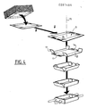
- the cutouts D used are not in themselves the subject of the invention. They are in particular in the form of originally flat blanks, of cardboard or equivalent, comprising (FIG. 4) fold lines 9 and complementary or juxtaposed parts intended to be joined together in particular by gluing to maintain volume. Thanks to the stamping, such cutouts D are set in volume, keep the volume which is given to them and can then receive contents to be packaged.
- the cutout D originally has a generally rectangular, planar shape, comprising a central bottom 10, and on each of its sides forming fold line 9 a flap intended to be placed perpendicular to the bottom 10 and upwards once the cut has been placed in volume. These flaps are therefore two longitudinal flaps 11 and two transverse flaps 12.
- Two opposite flaps for example the transverse flaps 12, are extended at each of their extreme edges forming a fold line 9 by a short tongue 13 intended to be glued, once the cutout D shaped, on the adjoining longitudinal flap 11 on its internal face, with lines of glue 14.
- Such a cut D can be multiformat, the bottom 10 having a rectangular shape or more or less square or flattened in elevation and absolute and relative dimensions (relative to each other) more or less variable.
- the same matrixing assembly 1 can be applied, after adjustment, to different cutouts D either of the same general shape but of different dimensions, or even of different shapes.
- the invention is applied to cutouts D having the same general shape (for example rectangular) and only the dimensions of which change.
- cutouts D having a generally rectangular or square shape, that is to say included in an envelope of generally parallelepiped shape once set in volume, the dimensions which are modified being the length and the width of the bottom 10 and the height of the cut D once stamped, that is to say the width of the flaps 11, 12.
- cutouts D are well known to those skilled in the art in the technical field of packaging and, for this reason, need not be described further.
- the general structures of a stamping assembly and of a stamping machine comprising such a stamping assembly as just described are well known to those skilled in the art in the technical field considered and , for this reason need not be described further.
- the description therefore mainly relates to the essential means of the invention aimed at ensuring automatic, rapid, precise and renewable adjustment of the stamping assembly 1 so as to be able to flexibly and automatically stamp cuts of different formats.
- a stamping method and machine carrying a stamping assembly 1, according to the invention, are generally such that the stamps to be stamped are brought to the unit, linearly, one after the other, the stamps D being placed horizontally, up to '' in a forging position in which a die to be stamped remains stationary to be stamped by the stamping assembly 1, the punch 2 cooperating with the die 3. More precisely, the blank D to be stamped is brought just above the die 3 while the punch 2 is spread vertically vertically above the die 3, the axis 15 of the stamping assembly 1 being vertical. Then, the die 3 remaining fixed, as a whole, the punch 2 is slid vertically and down along the axis 15 to come into contact with the blank D to be stamped and conform it by cooperating with the die 3. Then , once this stamping has been carried out, the punch 2 is dissociated from the die 3 and the stamped cutout can be released from the stamping assembly 1 in order to be evacuated, thanks to the extraction and evacuation means 8.
- Such a matrixing is generally carried out for series of several homogeneous cuts D, that is to say of the same format. In this case, there is no need, between each cutting, to carry out the dimensional adjustment of the matrixing assembly 1.
- the dimensional adjustment of the stamping assembly 1 is then carried out as described.
- the dimensional adjustment of the stamping assembly 1 being automatic, rapid, precise and reproducible, it is possible to conceive of a completely flexible stamping, the cutouts D for stamping arriving at the unit according to formats different from each other.
- the punch 2 is in the form of a rigid piece (but deformable) comprising a plurality of projecting angles juxtaposed horizontally.
- the matrix 3 also constitutes a rigid but deformable part comprising the same plurality of re-entrant angles.
- the salient angles of the punch 2 cooperate with the reentrant angles of the die 3, that is to say that the salient angles are placed inside the reentrant angles being separated laterally from a lateral swaging spacing dependent on the thickness of the cut D to be stamped.
- the punch 2 and the die 3 are each in several distinct parts, these parts constituting in particular, each, all or part of a respectively salient or reentrant angle. These constituent parts of the punch 2 or of the die 3 are of adjustable relative position, for the punch 2 and the die 3 respectively, so as to allow, as indicated, the dimensional adjustment of the stamping assembly 1.
- the blocking of the parts constituting the punch 2 or the die 3, in any desired relative adjustment position makes it possible to give the punch 2 and the die 3 the rigidity necessary for its operation.
- the relative displacements of the constituent parts of the punch 2 or of the die 3, respectively are called lateral configuration displacements. Indeed, these displacements are carried out in the lateral directions of the punch 2 or of the matrix 3 (that is to say in the direction of the contraction or in the direction of the expansion with respect to the axis 15) and they aim to modify the configuration of the punch 2 or of the matrix 3 to give it an appropriate dimension.
- the punch 2 and the die 3 are movable relative to each other as a whole, in a given configuration, along the axis 15 by axial interlocking-disengagement movements.
- the die 3 remains fixed and only the punch 2 is movable to slide along the axis 15.
- matrixing member is used to designate either the punch 2 or the matrix 3.
- each stamping member 2, 3 may be in a certain relative position corresponding to a certain configuration of the stamping member then forming a rigid assembly suitable for stamping.
- This state in which the constituent parts of each matrixing member 2, 3 are blocked in their relative displacement is called blocked state.
- This state in which the constituent parts of each matrixing member 2, 3 are blocked in their relative displacement is called blocked state.
- to allow the configuration of a matrixing member 2, 3 to be changed by lateral configuration displacements such movements are authorized by unlocking these constituent parts of each matrixing member.
- the stamping takes place in the locked state and the unlocked state is only a temporary state allowing the dimensional adjustment of the stamping members 2, 3.
- the two stamping members 2, 3 being structurally distinct, one of them can be in the blocked (or unlocked) state while the other is in the blocked or unlocked state.
- the matrixing members 2, 3 can be, taken as a whole, in several positions relative to each other. In one of these relative positions, the punch 2 is housed in the die 3, that is to say that the punch 2 and the die 3 are then substantially in the same place along the axis 15. In this case, the matrixing assembly 1 is said to be in the nested state. This nested state corresponds to an extreme lower position of the punch 2. Conversely, when the punch 2 is spread along the axis 15 of the die 3, therefore being released outside of the die 3, the stamping assembly 1 is said to be in the dislocated state. As necessary, each matrixing member 2,3 is in the locked state or in the unlocked state, depending on whether the matrixing assembly 1 is in the nested state or in the dislocated state.
- the dimensional adjustment of the stamping assembly is carried out while the punch 2 is in the stamping 3, that is to say in the nested state. Consequently, the unlocked state only intervenes in the nested state. And, in certain stages of the method and while the matrixing assembly 1 is in the nested state, one or / and the other of the matrixing members 2, 3 are in the blocked state. In the nested state, the matrixing members 2, 3 can have several possible relative configurations. In one of these possible relative configurations, there are between the punch 2 and the die 3 the desired lateral swaging spacings. In this case, the stamping assembly 1 is said to be in the stamping position. As is apparent from the description, other situations are possible in the nested state, in particular that where the punch 2 and the die 3 are in contact with one another, in the absence therefore of any lateral spacing between them.
- the matrixing assembly 1 can be in a waiting situation in which the two matrixing members 2, 3 are dislocated, blocked and with the lateral matrixing spacings between their reciprocal constituent parts therefore adapted to the thickness of the die cut.
- This waiting situation (FIG. 1) is that in which the punch 2 came out of the die 3 while being axially spaced therefrom, the dimensional adjustment of the punch 2 and of the die 3 being carried out and allowing subsequent stamping for an appropriate size cutout.
- This waiting situation is generally that in which the punch 2 is at its extreme upper position.
- the direction of supply of the cutouts D to be stamped is described as longitudinal. This direction is generally horizontal.
- the horizontal direction perpendicular to the longitudinal direction is called transverse.
- the longitudinal and transverse directions therefore define a horizontal plane and, in the case considered, the two directions in which the dimensional adjustment of the swaging assembly must be carried out.
- the following steps are carried out: First, in a wedging step, the two matrixing members are brought from their disengaged state to their nested and unlocked state with their parts reciprocal constitutive in contact, by displacements of configuration and interlocking-dislocation and in a predetermined reference configuration (FIG. 10B).
- first adjustment acts positively and directly on only one of the two matrixing members 2, 3 - qualified as a driving adjustment member - to ensure its displacement of configuration, this driving member adjustment acting in turn directly on the other matrixing member - qualified as a driven adjusting member- to ensure its configuration displacement, in synchronism, until a first stamping member 2, 3 is dimensionally adjusted .
- the first matrixing member 2, 3 is brought to the state blocked.
- a second adjustment step (FIG. 10D) one acts positively and directly on the only second matrixing member 2, 3 to ensure its configuration displacement in the direction of the lateral spacing relative to the first matrixing member 2, 3 until the lateral matrixing spacings are reached, the second matrixing member 2, 3 then being adjusted dimensionally.
- the second matrixing member is brought to the blocked state. And there is a displacement of interlocking-disengagement of the matrixing members 2, 3 to bring them to the waiting situation.
- the adjustment method comprises a setting step making it possible to reach a "zero point" corresponding to a relative position marked with the constituent parts of the punch 2 and of the die 3, position marked from which the lateral displacements are carried out. and can be controlled.
- a first adjustment step the dimensional adjustment of a first locking member is ensured. And, for this purpose, one acts positively with a view to displacing it on only one of the two matrixing members 2, 3.
- the dimensional adjustment of the second matrixing member is ensured for the finishing 'spreading laterally from the first stamping member, previously dimensioned, to make the necessary lateral stamping spacings between them.
- the method therefore comprises a subsequent step aimed at passing the matrixing assembly 1 from its nested state to its dislocated state in particular up to the waiting situation.
- one of the matrixing members 2, 3 is used as the driving member, that is to say displaced positively while the other matrixing member is driven member, that is to say that its configuration or the relative positions of the parts which constitute it are determined by the configuration of the driving member only, without acting positively and directly on the member led. It then follows simultaneous displacements of configuration of the two matrixing members 1, 2.
- This same type of drive means by driving member and driven member is preferably implemented in the setting step.
- the following steps are carried out starting from a waiting situation corresponding to a different cutout format: a nesting-dislodging movement of the two matrixing members to bring them to the nested state since it is in this state that the adjustment is made.
- the two matrixing members are brought to the unlocked state.
- One then acts positively and directly on only one of the two matrixing members - called then the leading wedging member - to ensure its displacement of configuration, this leading wedging member coming first in contact with the other member matrixing - qualified as a driven wedging member - then acting in turn directly on the driven wedging member to ensure its displacement of configuration in synchronism to the reference configuration (FIGS. 10A and 10B).
- the timing setting member is the same as the setting adjusting member; the driven setting member is the same as the driven adjusting member; the first matrixing member is the same as the driven adjusting member; the second matrixing member is the same as the driving adjustment member; the reference configuration is that of a format of extreme, minimum dimension, of one and the other of the two matrixing members; the respective displacements of configuration of the setting step on the one hand and of adjustment steps on the other hand are in opposite directions; the configuration displacements of the setting step are displacements in the direction of the contraction; the configuration movements of the adjustment steps are in the direction of expansion; the matrix is the driving adjusting member; the punch is the driven adjusting member.
- the invention could be applied, in other variants such as, in particular, the wedging drive member being the driven adjustment member; the first stamping member is the driving adjustment member; the reference configuration is that of the maximum format or any other; the matrix is the driven adjusting member and the punch the driving member.
- the preferred embodiment described is such that to ensure the configuration displacement of a driven matrixing member by means of a driving matrixing member, itself in displacement of configuration and the matrixing members being nested, either the member driven is elastically biased in contact with the driving member in the same direction as that in which it is solicited as a result of the displacement of the driving member (case of the first adjustment step), or the driven member is left free (case of the setting step).
- the punch 2 is elastically urged in the direction of expansion, the punch 2 coming into contact with the die 3 and acts on the matrix 3 in the direction of expansion in order to bring the punch 2, by expansion, to the desired state.
- the configuration movement of the first or second stamping member is made during the first setting step over strokes equal to the differences between the desired final dimensions of the first stamping member and the initial dimensions of the reference configuration.
- This characteristic is such that it allows automatic adjustment and reproducibility, the reference configuration being identified and the necessary displacement strokes being known depending on the format to be produced.
- the displacement of the second matrixing member over strokes equal to the lateral matrixing spacings.
- This characteristic also allows the automaticity and the reproducibility of the adjustment, the lateral stamping spacings being known as a function of the thickness of the cut to be stamped.
- the initial dimensions of the reference configuration, the desired final dimensions of the first stamping member and the lateral stamping spacings (or the thickness of the blank to be stamped) are stored ) and action is taken on a driving member with a view to ensuring its configuration displacement by identifying only the movement stroke of this driving member, which allows the automation of the process.
- a matrixing method according to the invention therefore implements the adjustment method which has just been described.
- a matrixing assembly 1 is such that the lateral drive and blocking means 4 of the two matrixing members 2, 3 are partially common to the two matrixing members and comprise, on the one hand, positive bidirectional drive means with locking possible in any position 16 associated with and acting directly on one of the two matrixing members, namely the driving adjustment member and, on the other hand, unidirectional elastic means with locking possible in any position associated with and acting directly on the other matrixing member, namely the driven member.
- the unidirectional elastic means 17 are released, they act on the driven adjusting member to urge it into contact with the driving member, the two stamping members 2, 3 then being fitted.
- the bidirectional means 16 can drive the driven adjusting member through the driving adjusting member.
- the bidirectional drive means with possible blocking 16 are identified by the movement of movement of the adjusting adjustment member and this in order to be able to control this displacement, allow the obtaining of a desired dimension and ensure the reproducibility of the adjustment.
- the bidirectional drive means with possible blocking 16 comprise at least one threaded rod 18 whose pivoting in one direction or the other is ensured by at least one motor 19, a tapped hole 20 of the driving adjustment member cooperating with the threaded rod 18.
- the unidirectional elastic means with possible blocking 17 comprise at least one compressed air cylinder acting on the driven adjusting member and a compressed air supply associated with the cylinder and capable of being cut with, in particular placing outdoors.
- These unidirectional elastic means with possible blocking 17 also include a positive blocking member 22 acting on the driven member.
- This positive blocking member is a blocking head driven by a jack 23 acting on the rod 21a of the compressed air cylinder 21.
- the compressed air cylinder 21 is a single-acting cylinder in particular acting in the direction of expansion of the driven member.
- the driven member comprises at least one sheath 24 forming a rigid block, longitudinally incorporating at least one compressed air cylinder 21 which thus makes it possible to guide at least one constituent part of the driven member.
- the actuator 23 for driving the blocking member 22 is fixed transversely on the sheath 24 in line with the compressed air actuator 21, orifices 25 for supplying compressed air or venting to the cylinders 21 and 23 also being provided in the sleeve 24.
- the adjusting drive member has four separate parts 26a, 26b, 26c, 26d carried by four separate support blocks 27.
- the bidirectional drive means with blocking 16 comprise firstly a first pair of threaded rods 18a, parallel to each other, each with two threads in opposite directions to the two end parts, cooperating with suitable tapped holes 20 of the support blocks 27, this first pair of threaded rods 18a being carried by bearing blocks 28.
- the first pair of threaded rods 18a extends by example transversely by being spread outwards from the parts 26a to 26d.
- Two bearing blocks 28 may be provided, each comprising a beam 29 and bearings 30, the beam 29 extending in transverse direction. The two bearing blocks 28 are also placed transversely, laterally and towards the outside of the matrixing assembly 1.
- the bidirectional drive means with blocking 16 secondly comprise a second pair of threaded rods 18b, parallel to each other, each having two end threads in opposite directions, cooperating with tapped holes 31 suitable for bearing blocks 28.
- the positive bidirectional drive means with blocking 16 comprise, thirdly, support bearings 32 of the second pair of threaded rods 18b carried by a frame 33 of the machine.
- the second pair of threaded rods 18b extends longitudinally away from the axis 15.
- the bidirectional drive means 16 comprise, fourthly, two motors 19a, 19b, carried by the frame 33, acting on the threaded rods 18a, 18b, respectively by means of two connecting means 34a, 34b connecting the two motors 19a, 19b with threaded rods 18a, 18b.
- the motor 19a can, for example, be carried by the frame 33 in the upper extreme position and drive by chains or equivalent 35 sprockets or pulleys or equivalent 36 carried by upper beams 37 of the frame 33.
- the sprockets or equivalent 36 can be connected by telescopic cardan shafts 38 to angle transmission boxes 39 themselves located at the end of the two rods of the first pair of threaded rods 18a.
- the motor 19b may be a brake gear motor carried by the frame 33 driving a chain 40 or equivalent, notably arranged transversely, in direct engagement with the two threaded rods of the second pair of threaded rods 18b.
- the positive half-directional drive means 16 also include, fifthly, motor control means 19a, 19b including means for locating and memorizing the number of turns or portions of turns performed by the threaded rods of the two pairs 18a, 18b so as to be able to identify the relative position of the constituent parts of the matrix 3.
- the two pairs of threaded rods 18a, 18b are arranged on the one hand longitudinally (in this case for the second pair of threaded rods 18b) and on the other hand transversely (for the first pair 18a). These threaded rods are placed towards the outside of the constituent parts of the matrix 3. Finally, these threaded rods provide between them a large clearance space in which the constituent parts of the matrix 3 are placed at the desired locations, these locations being variables depending on the dimensional setting of matrix 3.
- the driven member then comprises four distinct parts 41a to 41d constituting two pairs supported by two outer sleeves 24a, by means of the rods 21a of first compressed air jacks 21. These two outer sleeves 24a are carried by a central sleeve 24b by through the rods 21a of second compressed air cylinders 21.
- the unidirectional elastic means with blocking 17 firstly comprise at least four first compressed air jacks 21 arranged in parallel, one for each part of the driven member and two in opposite directions on each outer sheath 24a.
- the unidirectional elastic means with blocking 17 comprise at least two second compressed air jacks 21 arranged parallel to each other and perpendicular to the first jacks, one for each outer sheath 24a and the two opposite on the central sheath 24b.
- first blocking cylinders 23 carried by the outer sleeves 24a and acting on the first compressed air cylinders 21 carried by these outer sleeves 24a.
- the means 17 also comprise, fourthly, two second blocking cylinders 23 carried by the central sleeve 24b and acting on the second compressed air cylinders 21 carried by this central sleeve 24b.
- the means 17 comprise, in the fifth place, the compressed air supply or ventilation openings 25 on the two outer sleeves and the central sleeve 24a, 24b for supplying the jacks 21, 23, in communication, consequently , with on the one hand the first and second compressed air cylinders 21 and, on the other hand, with the first and second locking cylinders 23, on one side, these orifices 25 being in communication, on the other side, with cut-off compressed air supplies.
- Compressed air supplies can be shut off with shutdown the open air of the jack chambers 21, 23 so that the jack rods are then free.
- each first or second compressed air cylinder 21 is double, the two cylinders making it up being in close proximity to one another and there is associated with them a single blocking cylinder 23 acting on the two cylinder rods 21a.
- This arrangement allows the actuator rods 21a to maintain the sliding of the outer sleeves 24a and of the constituent parts 41a, 41b, 41c, 41d of the driven member.
- These constituent parts 41a, 41b, 41c, 41d are, in the case where the driven member is the punch, plates extending over a certain axial length along the axis 15 and over a certain length in the lateral direction.
- the sleeves 24a, 24b are constituted by blocks of generally parallelepipedal shape for example, also extending along the axis 15.
- the double jacks constituting each first or second compressed air jack 21 are superimposed in the same vertical plane.
- the outer vertical edges 42 of the constituent parts 41a, 41b, 41c, 41d are projecting or preferably coplanar with the outer faces 43 of the adjacent outer sleeves 24a, these outer faces 43 thus being able to participate in the stamping operation.
- the blocking head 22 is tapered at its outer end of attack directed towards the rods 21a and swollen at its rear end, directed towards the jack 23 while being furnished at least externally, of a flexible and / or non-slip material.
- the matrix 3 itself can be the subject of various embodiments of detail.
- each of the parts 26a, 26b, 26c, 26d comprises a folding plate 44 of the flap of the cutout D, fixedly carried by the support block 27 and, on the other hand, a presser 45 slidably mounted on the support block 27 by means of a jack 46.
- the folding sheet 44 and the presser 45 are arranged in two planes perpendicular to each other so as to constitute a re-entrant angle of the matrix 3.
- the folding sheets 44 are arranged in plans vertical and transverse while the pressers 45 are arranged in longitudinal planes.
- the folding plates 44 are adapted to the folding of the transverse flaps 12 while the pressers 45 are adapted to the folding of the longitudinal flaps 11.
- the sliding stroke of the pressers 45 is small.
- the pressers 45 are therefore movable between two extreme positions.
- An inactive, retracted position where they are furthest from each other and an active, protruding position, where they are closest to each other.
- the inactive position, retracted is that occurring at the start of stamping and authorizes the presence of a cutout D during stamping, the flaps 11 and the tongues 13 are not yet secured by gluing.
- the pressers 45 Under these conditions, in this retracted position, the pressers 45 are in a slightly larger configuration than the final configuration of the blank to be stamped.
- the active position of the pressers corresponds exactly to that of the stamping at the exact dimensions of the cut to be stamped.
- the flaps 11 are then pressed against the tongues 13.
- the matrix 3 may also include plates 47 for pre-folding the tongues 13, placed longitudinally as well as curved sheets 48 for folding the flaps, also placed longitudinally, the plates 47 and the sheets 48 being located in the upper upper part of the matrix 3, on the side of the introduction of the punch 2, while the folding sheets 44 and the pressers 45 are located in the lower part, the folding sheets 44 however extending to the upper part of the die 3.
- the mastering sequence is known per se.
- the cutout D to be stamped being flat and horizontal, first of all we first perform a pre-folding of the tongues 13, arranged longitudinally, using the plates 47. Then, we perform the folding of the longitudinal flaps 11 thanks to the sheets 48 and, simultaneously , the transverse flaps 12 are folded thanks to the sheets 44.
- the pressers 45 are hitherto in the inactive state. Then, they are brought to the active state so that the longitudinal flaps 11 are applied to the tongues 13, the previously deposited lines of glue 14 ensuring the assembly of the assembly.
- a stamping machine includes such a stamping assembly 1.
- the means forming a longitudinal stop 7 can be displaced longitudinally and can be locked in any position by means of drive and blocking means 49.
- These drive and blocking means 49 being controlled, depending on the format of die cut, so that it is wedged on the axis 15 of the die assembly 1.
- the drive and locking means 49 comprise for example a brake gear motor 50 carried by the frame 33, driving an endless chain or equivalent 51 engaged on a pinion 52 fixed on a threaded rod 53 mounted on a fixed nut 54 and carrying, moreover, the actual stop.
- the cut-out supply means 6 comprise two endless, continuously running, lateral and longitudinal bands 55, stretched between end drums 56 carried by two lateral and longitudinal support beams 57, themselves carried by the frame 33 transversely adjustable but lockable in any position by drive means 58 controlled as a function of the transverse format of the blank to be stamped.
- the endless belts 55 also extend downstream (relative to the direction of supply of the cutouts D) vertically in line with the die-forging assembly 1, transversely outside of it, in a plane slightly above the die 2.
- the endless bands 55 allow the relative sliding on themselves, of the cutout D in the forging position, cutout which is blocked by the means forming a stop 7 while being urged towards them by the endless bands 55 in motion.
- a gear motor 59 placed in particular in the lower position of the frame 33 drives a main shaft, in particular transverse 60, which drives, by appropriate connecting means 55a such as endless chains or belts the drums 56 therefore the endless belts 55.
- the drive means 58 comprise transverse threaded rods, comprising threads of opposite directions 61 carried by bearings 62 of the frame, driven in one direction or the other, to from a geared motor 63, also carried by the frame 33, via chain or equivalent 64.
- the cut supply means 6 also include at least one stop 65 for positive drive of the cutouts D.
- These tabs 65 are placed between the endless belts 55, upstream. They are driven in synchronism with the endless belts 55 by drive means 66 connected to the geared motor 59 as well as to the shaft 60 by a transmission 67 for part common to the connection means 55a.
- the tabs 65 allow the cutouts D to be driven by pushing them by their upstream (or rear) transverse edge.
- the tabs 65 have the effect of preventing the inadvertent sliding of a die cut to be stamped on the endless belts 55.
- a cleat 65 slides downstream as far as the middle part of the endless bands 55 and a support roller 68 ensuring a positive drive of the die to be stamped, driven in synchronism with the endless band placed opposite by drive and / or transmission and / or connection means, associated with means 55a and 67.
- the roller 68 has the effect of taking charge of the positive drive of a cut when the cleat 65 has disappeared in its extreme downstream position. It follows that the movement of the blank D in synchronism with the endless belts 55 is ensured which allows the location of the precise position of the blank D in motion. Near the roller 68 are placed means for detecting the cut to be stamped passing in line with the roller 68 such as a photoelectric cell.
- gluing means 69 for the lateral and longitudinal flaps 11 of the blank to be stamped.
- These gluing means 69 are controlled from an encoder 70 depending on the drive of the strips. endless 55 or support roller 68.
- the encoder 70 takes the form of a roller associated in particular with one of the end drums of the endless belts 55.
- This arrangement has the effect that according to a particularly longitudinal format of a die-cut to which corresponds a certain sizing program, the sizing means 69 are implemented precisely as a function of the position itself controlled of the cut on the endless belts 55.
- the gluing program consists in determining the lengths of the lines of glue 14 and their position on the longitudinal flaps 11.
- the cutting feed means 6 comprise at least one store 71 of cutouts stacked at right and above the endless belts 55, upstream, with lower extraction opening 72, with loading opening superior 73.
- the magazine 71 is suitable for receiving cutouts of different formats.
- the magazine 71 is associated with means 74 for extracting the blank present in the extraction opening 72, such as suction cups 75 with controlled operation and displacement, in particular carried by an arm 76 mounted to pivot about a transverse axis. 77 pivotally driven from the gear motor 59 and the shaft 60 by a transmission 78.
- the cross member 79 and the side members 80 are of a length capable of allowing the storage of cutouts according to the maximum format and the minimum format as well as any intermediate format.
- the die 3 is, as a whole, of general fixed position, slightly below the horizontal plane of the endless bands 55, while the punch 2 is mounted to slide vertically along the axis 15 above the matrix 3 being driven by the axial drive and blocking means 5.
- Such axial drive and blocking means 5 may comprise one or more vertical guides 81 on which are sliders 82 forming consoles and supporting a door beam punch 83, horizontal and transverse to which is rigidly fixed a punch holder 84, vertical and axial with axis 15, terminated at its lower part by the central sheath 24b.
- the slider 82 is driven vertically upwards or downwards, according to an appropriate kinematics, in particular from the geared motor 59 or the shaft 60 by means of an appropriate transmission 85.
- the extraction and evacuation means 8 firstly comprise temporary blocking members 86 of a die cut cut in the matrix active at the time of stamping, namely during pressing by the pressers 45 as well as when sliding the punch 2 vertically upward to disengage it from the die 3 after stamping, so that the stamped cutout remains temporarily in the die 3 in a fixed, predetermined and constant position without being driven by the punch 2 in motion.
- temporary blocking members 86 are, for example, suction cups carried by the pressers 45, associated with an appropriate vacuum supply.
- the extraction and evacuation means 8 comprise, secondly, gripping members 87, mobile, placed below the die 3, capable of coming to grip and transport a die cut from below, on the bottom 10, when the temporary blocking members 86 have become inactive, in order to transfer the stamped cutout to a conveyor 88.
- the gripping members 87 are for example suction cups associated with a vacuum supply carried by support means 89 ensure their movement in particular axially along the axis 15, connected by a transmission 90 to the gear motor 59 or to the 'shaft 60 or any other suitable motor.
- the conveyor 88 is for example a conveyor placed transversely below the matrix 3.
- the adjustment process which generally uses a programmable controller for controlling the adjustments of the various components and components of the machine, including the die-forging assembly 1, as a function of the dimensional characteristics of the cuts to be made.
- the appropriate magazine 71 must be adapted or selected, and likewise, the transverse spacing of the strips 55 must be adapted.
- the spacing of the endless belts 55 is achieved by the drive means 58.
- a cutout is extracted from the magazine 71 through the lower extraction opening 72 thanks to the suction cups 75 driven by the arm 76.
- the cutout to be stamped is deposited on endless belts 55 whose transverse spacing has therefore been previously adjusted.
- the endless bands 55 combined with the stopper 65 drive the die-cutting to the roller 68.
- the roller 68 clamps the die-cutting on the endless belt 55 so as to ensure its positive synchronous movement with the endless bands 55 and, as explained, the location of the cut. Thanks to the program and the data of the programmable controller, the gluing of the longitudinal flaps 11 is carried out by the gluing means 69 when the cut-out to be stamped is scrolled. In parallel, the longitudinal stop 7 has been adjusted and the punch 2 is in the waiting situation. The blank to be punched therefore arrives between the die 3 and the punch 2 in the exact stamping position determined by the longitudinal stop 7. It is then possible, thanks to the geared motor 59, to move the punch 2 vertically downward in the die 3 this which ensures the mastering of the cut.
- the suction cups 86 are implemented, with the pressers 45.
- the punch 2 can be released while, simultaneously, the suction cups 87 can come to grip the die cut and bring it on the conveyor 88.
- the following operations are carried out, in the absence of any cutout between the punch 2 and the die 3: There is a nesting / dislodging movement of the punch 2 and of the die 3 to bring them in the nested state.
- the punch 2 and the die 3 are brought to the unlocked state.
Abstract
Description
L'invention concerne un procédé de réglage dimensionnel d'un ensemble de matriçage de découpes, destinées à la réalisation de barquettes de conditionnement, un ensemble de matriçage pour la mise en oeuvre de ce procédé et un procédé et une machine de matriçage comportant un tel ensemble.The invention relates to a method of dimensional adjustment of a die-stamping assembly, intended for the production of packaging trays, a matrixing assembly for the implementation of this method and a method and a die-stamping machine comprising such a together.
On connaît déjà un procédé de matriçage de découpes au moyen d'un ensemble poinçon-matrice dans lequel successivement on extrait la découpe à matricer de moyens d'alimentation en découpes tel qu'un magasin ; on transfère la découpe à matricer ainsi extraite entre le poinçon et la matrice écartés l'un de l'autre ; on effectue un rapprochement relatif réciproque du poinçon et de la matrice jusqu'à les amener l'un contre l'autre de part et d'autre de la découpe pour le matricer ; on réalise, le cas échéant, une solidarisation positive de parties complémentaires ou juxtaposées de la découpe, notamment par collage ; on effectue un écartement relatif réciproque du poinçon et de la matrice ; et on extrait et évacue la découpe ainsi matricée.There is already known a die-stamping process by means of a punch-die assembly in which successively the die-cutting is extracted from die-feed means such as a magazine; transferring the die cut thus extracted between the punch and the die spaced from each other; a reciprocal relative approximation of the punch and of the matrix is carried out until they are brought one against the other on either side of the cut to stamp it; if necessary, a positive joining of complementary or juxtaposed parts of the cut is made, in particular by gluing; a reciprocal relative spacing of the punch and of the die is carried out; and the cut and stamped cut is extracted and removed.
Un dispositif de matriçage de découpes applicable notamment à une machine de conditionnement telle qu'une barquetteuse est également connu et comprend un poinçon et une matrice coopérant l'un avec l'autre ; des moyens pour le rapprochement et l'écartement relatif réciproque du poinçon et de la matrice dans leur ensemble entre deux positions extrêmes à savoir une position inactive où ils sont écartés l'un de l'autre et une position de matriçage proprement dit où ils sont associés l'un dans l'autre ; et des moyens d'extraction et d'évacuation des découpes matricées.A die-cutting device applicable in particular to a packaging machine such as a tray-stacker is also known and comprises a punch and a die cooperating with each other; means for the approximation and the reciprocal relative spacing of the punch and of the die as a whole between two extreme positions, namely an inactive position where they are separated from one another and a stamping position proper where they are associated with each other; and means for extracting and evacuating the stamped cuts.
On peut, par exemple, se référer au document FR 2 248 932.One can, for example, refer to
Ce procédé et ce dispositif de matriçage sont plus spécialement destinés à une machine de conditionnement comportant des moyens d'alimentation en découpes, des moyens d'extraction d'une découpe à matricer de ces moyens d'alimentation ; des moyens de transfert de cette découpe jusqu'au dispositif de matriçage, des moyens d'extraction de la découpe matricée du dispositif de matriçage et d'évacuation vers un autre poste notamment de remplissage avec des contenus à conditionner.This method and this die-stamping device are more specifically intended for a packaging machine comprising means for supplying blanks, means for extracting a blank to be stamped from these supply means; means for transferring this cut to the stamping device, means extraction of the stamped cutout from the stamping device and evacuation to another station, in particular for filling with contents to be packaged.
De tels procédés et dispositif de matriçage bien connus à ce jour sont généralement conçus pour fonctionner avec un format unique (format et/ou dimension) de découpes généralement en carton, comportant des lignes de pliages et des parties complémentaires ou juxtaposées destinées à être solidarisées notamment par collage (pattes, rabats, etc...). En effet, les machines de conditionnement les plus connues associées à de tels dispositifs de matriçage sont généralement elles-mêmes à format de découpe unique. Dès lors, le changement de format de découpe soit est impossible, soit est réalisé en changeant totalement et purement et simplement le poinçon et la matrice, soit est réalisé manuellement ce qui est long, fastidieux, peu précis, coûteux, etc...Such stamping methods and device well known to date are generally designed to operate with a single format (format and / or dimension) of cuts generally made of cardboard, comprising fold lines and complementary or juxtaposed parts intended to be secured in particular. by gluing (legs, flaps, etc ...). In fact, the most well-known packaging machines associated with such matrixing devices are generally themselves with a single cutting format. Consequently, the change of cutting format is either impossible, or is carried out by completely and purely and simply changing the punch and the die, or is carried out manually which is long, tedious, imprecise, costly, etc.
Le document US 3 218 940 décrit une machine de mise en forme d'un carton qui comporte un tel dispositif de matriçage, réglable de façon manuelle, pour être adapté à des découpes de carton de formats différents. A cet effet, le poinçon et la matrice du dispositif de matriçage sont réalisés chacun en plusieurs parties séparées, déplaçables mais blocables les unes par rapport aux autres dans les deux directions longitudinales et transversales, les moyens de guidage et d'entaînement de ces parties assurant ces déplacements et blocages. Toutefois ces déplacements et blocages sont manuels et d'ailleurs séparés et distincts pour le poinçon et la matrice, ce qui ne permet pas, en pratique, des réglages nombreux, rapides, faciles et reproductibles.Document US 3,218,940 describes a machine for shaping a carton which comprises such a die-stamping device, manually adjustable, to be suitable for cardboard cuts of different formats. To this end, the punch and the die of the stamping device are each made in several separate parts, movable but lockable with respect to each other in both longitudinal and transverse directions, the means for guiding and driving these parts ensuring these displacements and blockages. However, these displacements and blockages are manual and, moreover, separate and distinct for the punch and the die, which does not allow, in practice, numerous adjustments, rapid, easy and reproducible.
D'autres dispositifs sont également connus des documents US 2 641 973 US 2 798 416, DE 292 080, US 3 046 849, US 1 386 292, US 4 033 242 et US 3 357 700.Other devices are also known from documents US 2,641,973 US 2,798,416, DE 292,080, US 3,046,849, US 1,386,292, US 4,033,242 and US 3,357,700.
On connaît aussi, dans le domaine général de l'emballage, la possibilité de régler les organes d'une machine, selon les conditions d'emploi, notamment les dimensions des emballages traités (documents FR 2 029 300 et EP 0142 007). Mais de tels réglages ne sont pas adaptés au cas du matriçage de découpes.We also know, in the general field of packaging, the possibility of adjusting the components of a machine, according to the conditions of use, in particular the dimensions of the treated packages (
L'invention a donc pour premier objet de résoudre les problèmes que posent le réglage d'un ensemble de matriçage dont chaque organe de matriçage est en plusieurs parties réglables et blocables. Plus spécifiquement, l'invention a pour objet d'assurer un réglage automatique, rapide, précis et reproductible. L'invention a pour second objet principal de mettre en oeuvre un tel réglage dans le cas du conditionnement.The first object of the invention is therefore to solve the problems posed by the adjustment of a matrixing assembly, each matrixing member of which is in several adjustable and lockable parts. More specifically, the object of the invention is to provide automatic, rapid, precise and reproducible adjustment. The second main object of the invention is to implement such an adjustment in the case of packaging.
A cet effet, l'invention propose d'abord un procédé de réglage dimensionnel d'un ensemble de matriçage comportant deux organes de matriçage : poinçon et matrice, chacun en plusieurs parties distinctes de positions relatives réglables et blocables par des déplacements latéraux de configuration, les deux organes de matriçage étant mobiles l'un par rapport à l'autre, dans leur ensemble, par des déplacements axiaux d'emboîtement-déboîtement, les deux organes de matriçage se trouvant d'une part, chacun séparément, soit à l'état bloqué, soit à l'état débloqué et, d'autre part, ensemble, soit à l'état emboîté, soit à l'état déboîté, en vue d'adapter dimensionnellement l'ensemble de matriçage à un format de découpe à matricer et de l'amener dans une situation d'attente à partir de laquelle le matriçage de la découpe est rendu possible par la coopération ultérieure des deux organes de matriçage, cette situation d'attente étant telle que les deux organes de matriçage soient déboîtés, bloqués et avec des écartements latéraux de matriçage entre leurs parties constitutives réciproques adaptés à l'épaisseur de la découpe à matricer, dans lequel on amène d'abord les deux organes de matriçage à l'état débloqué, on réalise ensuite les déplacements transversaux de configuration appropriés, on amène enfin les deux organes de matriçage à l'état bloqué, caractérisé en ce que l'on réalise les étapes suivante : on amène d'abord dans une étape de calage les deux organes de matriçage à partir de leur état déboîté jusqu'à leur état emboîté et débloqué, avec leurs parties constitutives réciproques en contact, par des déplacements de configuration et d'emboîtement-déboîtement, et dans une configuration de référence pré-déterminée ; ensuite, dans une étape de premier réglage on agit positivement et directement sur l'un seulement des deux organes de matriçage -l'organe menant de réglage - pour assurer son déplacement de configuration, l'organe menant de réglage agissant à son tour directement sur l'autre organe de matriçage -l'organe mené de réglage- pour assurer son déplacement de configuration, en synchronisme, jusqu'à ce qu'un premier organe de matriçage soit réglé dimentionnellement ; et, ensuite, on amène le premier organe de matriçage à l'état bloqué ; dans une étape de second réglage on agit positivement et directement sur le seul second organe de matriçage pour assurer son déplacement de configuration dans le sens de l'écartement latéral par rapport au premier organe de matriçage, jusqu'à atteindre les écartements latéraux de matriçage, le second organe de matriçage étant alors réglé dimensionnellement; on amène le second organe de matriçage à l'état bloqué ; et on assure un déplacement d'emboîtement-déboîtement des deux organes de matriçage pour les amener à la situation d'attente, ce qui a pour effet d'assurer un réglage automatique, rapide, précis et reproductible de l'ensemble de matriçage.To this end, the invention firstly proposes a method of dimensional adjustment of a stamping assembly comprising two stamping members: punch and die, each in several distinct parts of relative positions adjustable and lockable by lateral configuration displacements, the two matrixing members being movable relative to each other, as a whole, by axial interlocking-dislodging movements, the two matrixing members being located on the one hand, each separately, either at blocked state, either in the unlocked state and, on the other hand, together, either in the nested state, or in the dislocated state, with a view to dimensionally adapting the stamping assembly to a die cut format and bring it into a waiting situation from which the forging of the cut is made possible by the subsequent cooperation of the two forging members, this waiting situation being such that the two forging members are disengaged, blocked and with lateral stamping spacings between their reciprocal constituent parts adapted to the thickness of the blank to be stamped, in which the two stamping members are first brought to the unlocked state, the transverse displacements of appropriate configuration are then carried out, finally, the two matrixing members are brought to the locked state, characterized in that the following steps are carried out: first, in a wedging step, the two matrixing members are brought from their disengaged state to their nested and unlocked state, with their reciprocal constituent parts in contact, by configuration displacements and interlocking-disengagement, and in a predetermined reference configuration; then, in a first adjustment stage, one acts positively and directly on only one of the two matrixing members - the adjusting adjusting member - to ensure its displacement of configuration, the adjusting adjusting member acting in turn directly on the other matrixing member -the driven adjusting member- to ensure its configuration displacement, in synchronism, until a first matrixing member is adjusted dimensionally; and then the first matrixing member is brought to the blocked state; in a second adjustment step, the only second stamping member is acted positively and directly to ensure its configuration displacement in the direction of the lateral spacing with respect to the first stamping member, until the lateral stamping spacings are reached, the second matrixing member then being dimensionally adjusted; the second matrixing member is brought to the blocked state; and there is an interlocking-dislodging movement of the two matrixing members to bring them to the waiting situation, which has the effect of ensuring automatic, rapid, precise and reproducible adjustment of the matrixing assembly.
L'invention propose, ensuite, un ensemble de matriçage de découpes, comportant deux organes de matriçage : poinçon et matrice, chacun en plusieurs parties distinctes de positions relatives réglables et blocables par des déplacements latéraux de configuration grâce à des moyens latéraux d'entraînement et de blocage, les deux organes de matriçage étant mobiles l'un par rapport à l'autre, dans leur ensemble, par des déplacements axiaux d'emboîtement grâce à des moyens axiaux d'entraînement et de blocage, les deux organes de matriçage se trouvant, d'une part, chacun séparément, soit à l'état bloqué, soit à l'état débloqué et, d'autre part, ensemble, soit à l'état emboîté soit à l'état déboîté, en vue d'adapter dimensionnellement l'ensemble de matriçage, pouvant se trouver notamment en une situation d'attente dans laquelle les organes de matriçage sont déboîtés, bloqués et avec des écartements latéraux de matriçage entre leurs parties constitutives réciproques et en une position de matriçage dans laquelle les organes de matriçage sont emboîtés et coopèrent pour le matriçage effectif d'une découpe placée entre eux caractérisé en ce que les moyens latéraux d'entraînement et de blocage des deux organes de matriçage sont partiellement communs aux deux organes de matriçage et comprennent, d'une part, des moyens positifs d'entraînement bidirectionnels avec blocage possible en toute position, associés à et agissant directement sur l'un des deux organes de matriçage -l'organe menant - et, d'autre part, des moyens élastiques unidirectionnels avec blocage possible en toute position associés à et agissant directement sur l'autre organe de matriçage -l'organe mené- de manière que lorsque les moyens élastiques unidirectionnels sont débloqués, en premier lieu, ces moyens agissent sur l'organe mené pour le solliciter au contact de l'organe menant, les deux organes de matriçage étant emboîtés, et, en second lieu, les moyens d'entraînement bidirectionnels entraînent indirectement l'organe mené par l'intermédiaire de l'organe menant.The invention then proposes a set of die-forging cutouts, comprising two die-stamping members: punch and die, each in several distinct parts of relative positions adjustable and lockable by lateral configuration displacements thanks to lateral drive means and blocking, the two matrixing members being movable relative to each other, as a whole, by axial interlocking movements by means of axial drive and blocking means, the two matrixing members being , on the one hand, each separately, either in the locked state, or in the unlocked state and, on the other hand, together, either in the nested state or in the unblocked state, in order to adapt dimensionally the matrixing assembly, which can be in particular in a waiting situation in which the matrixing members are dislocated, blocked and with lateral matrixing spacings between their reciprocal constituent parts and in a matrixing position e in which the stamping members are fitted and cooperate for the effective stamping of a cutout placed between them characterized in that the lateral means for driving and blocking the two stamping members are partially common to the two stamping members and comprise , on the one hand, positive bidirectional drive means with possible locking in any position, associated with and acting directly on one of the two forging members - the driving member - and, on the other hand, elastic means unidirectional with blocking possible in any position associated with and acting directly on the other matrixing member -the member driven- so that when the elastic means unidirectional are unlocked, firstly, these means act on the driven member to urge it in contact with the driving member, the two matrixing members being nested, and, secondly, the bidirectional drive means indirectly drive the organ driven through the leading organ.
L'invention propose, enfin, d'une part, un procédé de matriçage de découpes et, d'autre part, une machine de matriçage mettant en oeuvre ce procédé de réglage et cet ensemble de matriçage, destinés plus spécialement au conditionnement.The invention finally proposes, on the one hand, a die-stamping process and, on the other hand, a stamping machine implementing this adjustment process and this stamping assembly, intended more specifically for packaging.
L'une des dispositions techniques assurant l'automaticité, la rapidité, la précision et la reproductibilité du réglage de l'ensemble de matriçage est la mise en oeuvre de moyens de réglage mécanisés, pouvant donc être contrôlés, agissant directement sur l'un seulement des deux organes de matriçage pour le déplacer -dit organe menant- lequel assure, à son tour, le déplacement de l'autre organe de matriçage -dit organe mené-. A cet effet, des moyens élastiques agissent sur l'organe mené pour solliciter au contact de l'organe menant. Et le réglage est effectué lorsque les deux organes de matriçage sont emboîtés l'un dans l'autre. Préférentiellement l'organe menant est la matrice qui peut ainsi envelopper le poinçon soumis élastiquement dans le sens de l'expansion à des vérins à air comprimé. Des tiges filetées motrices assurent les déplacements latéraux de configuration de la matrice et permettent un repérage de position de celle-ci. Pour permettre la reproductibilité, il est prévu préférentiellement une étape initiale de calage des deux organes de matriçage sur un point zéro correspondant à un format extrême, notamment minimal.One of the technical provisions ensuring the automaticity, the speed, the precision and the reproducibility of the adjustment of the matrixing assembly is the implementation of mechanized adjustment means, which can therefore be controlled, acting directly on only one of the two matrixing members for moving it - said driving member - which in turn ensures the displacement of the other matrixing member - said driven member. To this end, elastic means act on the driven member to urge on contact with the driving member. And the adjustment is made when the two matrixing members are nested one inside the other. Preferably, the driving member is the matrix which can thus envelop the punch subjected elastically in the direction of expansion to compressed air jacks. Driving threaded rods ensure the lateral displacements of the configuration of the matrix and allow the position of the latter to be identified. To allow reproducibility, there is preferably provided an initial step of setting the two matrixing members to a zero point corresponding to an extreme format, in particular a minimal format.
Les autres caractéristiques et avantages de l'invention résulteront de la description qui suivra en référence aux dessins annexés dans lesquels :
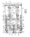
- - La figure 1 est une vue schématique en élévation d'une machine de matriçage selon l'invention.
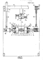
- - La figure 2 est une vue schématique de dessus, partielle, de la machine de matriçage selon l'invention, le poinçon n'étant pas représenté.
- - La figure 3 est une vue schématique de dessus, à plus grande échelle de la machine de matriçage selon l'invention, l'ensemble de matriçage étant représenté avec une découpe en cours de matriçage.
- - La figure 4 est un schéma illustrant les étapes de matriçage de la découpe.
- - La figure 5 est une vue en coupe schématique par un plan vertical transversal illustrant l'ensemble de matriçage.
- - La figure 6 est une vue schématique en perspective du poinçon de l'ensemble de matriçage.
- - La figure 7 et la figure 8 sont deux vues schématiques partielles en coupe selon les lignes VII-VII et VIII-VIII de la figure 6 illustrant des détails du dispositif des détails du poinçon de la machine de matriçage.
- - La figure 9 est une vue schématique des moyens d'alimentation des coupes et des moyens de butée longitudinale de la machine de matriçage selon l'invention.
- - Les figures 10 A, 10 B, 10 C et 10 D, sont quatre vues schématiques de dessus illustrant des étapes successives de réglage de l'ensemble de matriçage selon l'invention.
- - Figure 1 is a schematic elevational view of a stamping machine according to the invention.
- - Figure 2 is a schematic top view, partial, of the stamping machine according to the invention, the punch not being shown.
- - Figure 3 is a schematic top view, on a larger scale of the stamping machine according to the invention, the stamping assembly being shown with a cutout during stamping.
- - Figure 4 is a diagram illustrating the stages of die cutting.
- - Figure 5 is a schematic sectional view through a vertical transverse plane illustrating the matrix assembly.
- - Figure 6 is a schematic perspective view of the punch of the stamping assembly.
- - Figure 7 and Figure 8 are two partial schematic sectional views along lines VII-VII and VIII-VIII of Figure 6 illustrating details of the device details of the punch of the stamping machine.
- - Figure 9 is a schematic view of the means for feeding the cuts and the longitudinal stop means of the stamping machine according to the invention.
- - Figures 10 A, 10 B, 10 C and 10 D, are four schematic views from above illustrating successive stages of adjustment of the matrixing assembly according to the invention.
L'invention concerne un procédé de réglage dimensionnel d'un ensemble de matriçage 1 de découpes D destinées notamment à la réalisation de barquettes de conditionnement. Elle concerne également l'ensemble de matriçage 1 pour la mise en oeuvre de ce procédé de réglage. Elle concerne enfin un procédé et une machine de matriçage comportant un tel ensemble de matriçage 1.The invention relates to a method of dimensional adjustment of a
L'ensemble de matriçage 1 comporte, de façon connue en soi, deux organes de matriçage à savoir un poinçon 2 et une matrice 3, chacun en plusieurs parties distinctes de positions relatives réglables et blocables par des déplacements latéraux de configuration grâce à des moyens latéraux d'entraînement et de blocage 4. Les deux organes de matriçage 2, 3 sont mobiles l'un par rapport à l'autre, dans leur ensemble par des déplacements axiaux d'entraînement et de blocage grâce à des moyens axiaux d'entraînement et de blocage 5. Les deux organes de matriçage 2, 3 se trouvent d'une part, chacun séparément, soit à l'état bloqué, soit à l'état débloqué et, d'autre part, ensemble, soit à l'état emboîté, soit à l'état déboîté. Un tel ensemble de matriçage 1 peut être adapté dimensionnellement à un format donné de découpe à matricer et peut se trouver notamment en une situation d'attente dans laquelle les organes de matriçage 2, 3 sont déboîtés, bloqués et avec des écartements latéraux de matriçage entre leurs parties constitutives réciproques et en une position de matriçage dans laquelle les organes de matriçage 2, 3 sont emboîtés à partir de la situation d'attente et coopèrent pour le matriçage effectif d'une découpe placée entre eux.The
Un procédé de réglage dimensionnel d'un tel ensemble de matriçage 1 est tel que, de façon connue en soi, on amène d'abord les deux organes de matriçage 2, 3 à l'état débloqué, on réalise ensuite les déplacements latéraux de configuration appropriés, on amène enfin les deux organes de matriçage 2, 3 à l'état bloqué.A method of dimensional adjustment of such a
Un tel ensemble de matriçage 1 peut être incorporé à une machine de matriçage de découpes, destinée notamment à la réalisation de barquettes de conditionnement, comprenant, outre l'ensemble de matriçage 1, des moyens d'alimentation en découpes 6, des moyens formant butée longitudinale 7, associés aux moyens d'alimentation 6 et aptes à bloquer la découpe D à matricer dans la position convenable en vue de son matriçage par l'ensemble de matriçage 1 ; et, des moyens d'extraction et d'évacuation 8 d'une découpe D matricée.Such a die-
Les découpes D utilisées ne font pas en soi l'objet de l'invention. Elles se présentent notamment sous forme de flans originellement plats, en carton ou équivalent, comportant (figure 4) des lignes de pliage 9 et des parties complémentaires ou juxtaposées destinées à être solidarisées notamment par collage pour le maintien en volume. Grâce au matriçage, de telles découpes D sont mises en volume, gardent le volume qui leur est donné et peuvent ensuite recevoir des contenus à conditionner. Dans une forme de réalisation classique, la découpe D a, originellement, une forme générale rectangulaire, plane, comprenant un fond 10, central, et sur, chacun de ses côtés formant ligne de pliage 9 un rabat destiné à être placé perpendiculairement au fond 10 et vers le haut une fois la découpe mise en volume. Ces rabats sont donc deux rabats longitudinaux 11 et deux rabats transversaux 12. Deux rabats opposés, par exemple les rabats transversaux 12, sont prolongés à chacun de leur bord extrême formant ligne de pliage 9 par une courte languette 13 destinée à être collée, une fois la découpe D mise en forme, sur le rabat longitudinal attenant 11 sur sa face interne, par des traits de colle 14.The cutouts D used are not in themselves the subject of the invention. They are in particular in the form of originally flat blanks, of cardboard or equivalent, comprising (FIG. 4)
Une telle découpe D peut être multiformats, le fond 10 ayant une forme rectangulaire ou plus ou moins carrée ou applatie en élévation et des dimensions absolues et relatives (les unes par rapport aux autres) plus ou moins variables.Such a cut D can be multiformat, the
L'invention s'applique toutefois à d'autres formes générales de découpes : triangulaires, polygonales, cylindriques, etc. Ces découpes peuvent, de plus, être destinées à d'autres usages qu'une barquette.The invention however applies to other general forms of cuts: triangular, polygonal, cylindrical, etc. These cuts can, moreover, be intended for other uses than a tray.
Ainsi que cela résulte de la description, le même ensemble de matriçage 1 peut être appliqué, après réglage, à des découpes D différentes soit de même forme générale mais de dimensions différentes, soit même de formes différentes. Préférentiellement, l'invention est appliquée à des découpes D ayant une même forme générale (par exemple rectangulaire) et dont seules les dimensions changent.As follows from the description, the
L'invention est plus particulièrement décrite dans le cas de découpes D ayant une forme générale rectangulaire ou carrée, c'est-à-dire incluse dans une enveloppe de forme générale parallèlipédique une fois mise en volume, les dimensions qui sont modifiées étant la longueur et la largeur du fond 10 et la hauteur de la découpe D une fois matricée, c'est-à-dire la largeur des rabats 11, 12.The invention is more particularly described in the case of cutouts D having a generally rectangular or square shape, that is to say included in an envelope of generally parallelepiped shape once set in volume, the dimensions which are modified being the length and the width of the bottom 10 and the height of the cut D once stamped, that is to say the width of the
De telles découpes D sont bien connues de l'homme du métier dans le domaine technique de l'emballage et, pour cette raison, n'ont pas à être décrites davantage. De même, les structures générales d'un ensemble de matriçage et d'une machine de matriçage comportant un tel ensemble de matriçage ainsi qu'il vient d'être décrit, sont bien connues de l'homme du métier dans le domaine technique considéré et, pour cette raison n'ont pas à être décrits davantage. La description porte donc surtout sur les moyens essentiels de l'invention visant à assurer un réglage automatique, rapide, précis et reconductible de l'ensemble de matriçage 1 de manière à pouvoir matricer de façon flexible et automatique des découpes de formats différents.Such cutouts D are well known to those skilled in the art in the technical field of packaging and, for this reason, need not be described further. Likewise, the general structures of a stamping assembly and of a stamping machine comprising such a stamping assembly as just described, are well known to those skilled in the art in the technical field considered and , for this reason need not be described further. The description therefore mainly relates to the essential means of the invention aimed at ensuring automatic, rapid, precise and renewable adjustment of the stamping
Un procédé et une machine de matriçage portant un ensemble de matriçage 1, selon l'invention, sont généralement tels que les découpes à matricer sont amenées à l'unité, linéairement, les unes après les autres, les découpes D étant placées horizontalement, jusqu'à une position de matriçage dans laquelle une découpe à matricer reste stationnaire pour être matricée par l'ensemble de matriçage 1, le poinçon 2 coopérant avec la matrice 3. Plus précisément, la découpe D à matricer est amenée juste au-dessus de la matrice 3 alors que le poinçon 2 est écarté verticalement à l'aplomb au-dessus de la matrice 3, l'axe 15 de l'ensemble de matriçage 1 étant vertical. Puis, la matrice 3 restant fixe, dans son ensemble, le poinçon 2 est coulissé verticalement et vers le bas le long de l'axe 15 pour venir au contact de la découpe D à matricer et la conformer en coopérant avec la matrice 3. Ensuite, une fois ce matriçage réalisé, le poinçon 2 est dissocié de la matrice 3 et la découpe matricée peut être dégagée de l'ensemble de matriçage 1 pour être évacuée, grâce aux moyens d'extraction et d'évacuation 8.A stamping method and machine carrying a stamping
Un tel matriçage est généralement réalisé pour des séries de plusieurs découpes D homogènes c'est-à-dire de même format. Dans ce cas, il n'y a pas lieu, entre chaque découpe, de procéder au réglage dimensionnel de l'ensemble de matriçage 1. Lorsque, après le matriçage d'une telle série de découpes d'un certain format, on veut changer le format de découpes à matricer, on procède alors au réglage dimensionnel de l'ensemble de matriçage 1 ainsi qu'il est décrit. Toutefois, le réglage dimensionnel de l'ensemble de matriçage 1 étant automatique, rapide précis et reproductible, on peut concevoir un matriçage totalement flexible, les découpes D à matricer arrivant à l'unité selon des formats différents les uns des autres.Such a matrixing is generally carried out for series of several homogeneous cuts D, that is to say of the same format. In this case, there is no need, between each cutting, to carry out the dimensional adjustment of the
D'une façon générale, le poinçon 2 se présente sous la forme d'une pièce rigide (mais déformable) comportant une pluralité d'angles saillants juxtaposés horizontalement. Et, la matrice 3 constitue également une pièce rigide mais déformable comportant la même pluralité d'angles rentrants. Les angles saillants du poinçon 2 coopèrent avec les angles rentrants de la matrice 3 c'est-à-dire que les angles saillants sont placés à l'intérieur des angles rentrants en étant écartés latéralement d'un écartement latéral de matriçage dépendant de l'épaisseur de la découpe D à matricer.Generally, the
Le poinçon 2 et la matrice 3 sont chacun en plusieurs parties distinctes, ces parties constituant notamment, chacune, tout ou partie d'un angle respectivement saillant ou rentrant. Ces parties constitutives du poinçon 2 ou de la matrice 3 sont de position relative réglable, pour le poinçon 2 et la matrice 3 respectivement, de manière à permettre, comme indiqué, le réglage dimensionnel de l'ensemble de matriçage 1. Le blocage des parties constitutives du poinçon 2 ou de la matrice 3, en toute position relative de réglage souhaitée permet de conférer au poinçon 2 et à la matrice 3 la rigidité nécessaire à son fonctionnement.The
Par convention, les déplacements relatifs des parties constitutives du poinçon 2 ou de la matrice 3, respectivement, sont appelés déplacements latéraux de configuration. En effet, ces déplacements sont effectués dans les directions latérales du poinçon 2 ou de la matrice 3 (c'est-à-dire dans le sens de la contraction ou dans le sens de l'expansion par rapport à l'axe 15) et ils visent à modifier la configuration du poinçon 2 ou de la matrice 3 pour lui donner une dimension appropriée.By convention, the relative displacements of the constituent parts of the
Le poinçon 2 et la matrice 3 sont mobiles l'un par rapport à l'autre dans leur ensemble, dans une configuration donnée, le long de l'axe 15 par des déplacements axiaux d'emboîtement-déboîtement. Préférentiellement, la matrice 3 reste fixe et seul le poinçon 2 est mobile à coulissement le long de l'axe 15.The
Dans le texte, on utilise l'expression "organe de matriçage" pour désigner indifféremment le poinçon 2 ou la matrice 3.In the text, the expression "matrixing member" is used to designate either the
Ainsi que cela résulte de ce qui précède, les parties constitutives de chaque organe de matriçage 2, 3 peuvent se trouver dans une certaine position relative correspondant à une certaine configuration de l'organe de matriçage formant alors un ensemble rigide apte au matriçage. Cet état dans lequel les parties constitutives de chaque organe de matriçage 2, 3 sont bloquées dans leur déplacement relatif est appelé état bloqué. Inversement pour permettre le changement de configuration d'un organe de matriçage 2, 3 par des déplacements latéraux de configuration, on autorise de tels déplacements en débloquant ces parties constitutives de chaque organe de matriçage. Cela correspond à l'état débloqué. Le matriçage intervient à l'état bloqué et l'état débloqué est seulement un état temporaire permettant le réglage dimensionnel des organes de matriçage 2, 3. Les deux organes de matriçage 2, 3 étant structurellement distincts, l'un d'entre eux peut être à l'état bloqué (ou débloqué) alors que l'autre est à l'état bloqué ou débloqué.As follows from the above, the constituent parts of each stamping
Par ailleurs, les organes de matriçage 2, 3 peuvent se trouver, pris dans leur ensemble, dans plusieurs positions relatives l'un par rapport à l'autre. Dans une de ces positions relatives, le poinçon 2 est logé dans la matrice 3 c'est-à-dire que le poinçon 2 et la matrice 3 se trouvent alors sensiblement au même endroit le long de l'axe 15. Dans ce cas, l'ensemble de matriçage 1 est dit à l'état emboîté. Cet état emboîté correspond à une position extrême inférieure du poinçon 2. Inversement, lorsque le poinçon 2 est écarté le long de l'axe 15 de la matrice 3 en étant donc dégagé à l'extérieur de la matrice 3, l'ensemble de matriçage 1 est dit à l'état déboîté. Selon les nécessités, chaque organe de matriçage 2,3 est à l'état bloqué ou à l'état débloqué, selon que l'ensemble de matriçage 1 est à l'état emboîté ou à l'état déboîté.Furthermore, the
Ainsi que cela résulte de l'invention, le réglage dimensionnel de l'ensemble de matriçage est réalisé alors que le poinçon 2 se trouve dans la matriçe 3 c'est-à-dire à l'état emboîté. Dès lors, l'état débloqué n'intervient qu'à l'état emboîté. Et, dans certaines étapes du procédé et alors que l'ensemble de matriçage 1 est à l'état emboîté, l'un ou/et l'autre des organes de matriçage 2, 3 sont à l'état bloqué. A l'état emboîté, les organes de matriçage 2, 3 peuvent avoir plusieurs configurations relatives possibles. Dans une de ces configurations relatives possibles, il existe entre le poinçon 2 et la matrice 3 les écartements latéraux de matriçage souhaités. Dans ce cas, l'ensemble de matriçage 1 est dit en position de matriçage. Ainsi que cela résulte de la description, d'autres situations sont possibles à l'état emboîté notamment celle où le poinçon 2 et la matrice 3 sont en contact l'un contre l'autre, en l'absence donc de tout écartement latéral entre eux.As this results from the invention, the dimensional adjustment of the stamping assembly is carried out while the
Par ailleurs, l'ensemble de matriçage 1 peut se trouver dans une situation d'attente dans laquelle les deux organes de matriçage 2, 3 sont déboîtés, bloqués et avec les écartements latéraux de matriçage entre leurs parties constitutives réciproques adaptées donc à l'épaisseur de la découpe à matricer. Cette situation d'attente (figure 1) est celle dans laquelle le poinçon 2 est sorti de la matrice 3 en étant écarté axialement de celle-ci, le réglage dimensionnel du poinçon 2 et de la matrice 3 étant réalisé et permettant un matriçage ultérieur pour une découpe de format approprié. Cette situation d'attente est généralement celle où le poinçon 2 est à sa position extrême supérieure.Furthermore, the
Dans le texte, on qualifie de longitudinale la direction d'amenée des découpes D à matricer. Cette direction est généralement horizontale. On qualifie de transversale la direction horizontale perpendiculaire à la direction longitudinale. Les directions longitudinales et transversales définissent donc un plan horizontal et, dans le cas de figure considéré, les deux directions selon lesquelles le réglage dimensionnel de l'ensemble de matriçage doit être réalisé.In the text, the direction of supply of the cutouts D to be stamped is described as longitudinal. This direction is generally horizontal. The horizontal direction perpendicular to the longitudinal direction is called transverse. The longitudinal and transverse directions therefore define a horizontal plane and, in the case considered, the two directions in which the dimensional adjustment of the swaging assembly must be carried out.
Dans le procédé de réglage selon l'invention, on réalise les étapes suivantes : On amène d'abord, dans une étape de calage, les deux organes de matriçage à partir de leur état déboîté jusqu'à leur état emboîté et débloqué avec leurs parties constitutives réciproques en contact, par des déplacements de configuration et d'emboîtement-déboîtement et dans une configuration de référence prédéterminée (figure 10B).In the adjustment method according to the invention, the following steps are carried out: First, in a wedging step, the two matrixing members are brought from their disengaged state to their nested and unlocked state with their parts reciprocal constitutive in contact, by displacements of configuration and interlocking-dislocation and in a predetermined reference configuration (FIG. 10B).
Ensuite, dans une étape de premier réglage (figure 10C), on agit positivement et directement sur l'un seulement des deux organes de matriçage 2, 3 -qualifié d'organe menant de réglage- pour assurer son déplacement de configuration, cet organe menant de réglage agissant à son tour directement sur l'autre organe de matriçage - qualifié d'organe mené de réglage- pour assurer son déplacement de configuration, en synchronisme, jusqu'à ce qu'un premier organe de matriçage 2, 3 soit réglé dimensionnellement.Then, in a step of first adjustment (FIG. 10C), one acts positively and directly on only one of the two
Ensuite, on amène le premier organe de matriçage 2, 3 à l'état bloqué. Dans une étape de second réglage (figure 10D), on agit positivement et directement sur le seul second organe de matriçage 2, 3 pour assurer son déplacement de configuration dans le sens de l'écartement latéral par rapport au premier organe de matriçage 2, 3 jusqu'à atteindre les écartements latéraux de matriçage, le second organe de matriçage 2, 3 étant alors réglé dimensionnellement. On amène le second organe de matriçage à l'état bloqué. Et on assure un déplacement d'emboîtement-déboîtement des organes de matriçage 2, 3 pour les amener à la situation d'attente.Then, the
Par conséquent, le procédé de réglage comporte une étape de calage permettant d'atteindre un "point zéro" correspondant à une position relative repérée des parties constitutives du poinçon 2 et de la matrice 3, position repérée à partir de laquelle les déplacements latéraux sont réalisés et peuvent être contrôlés. Dans une étape de premier réglage, on assure le réglage dimensionnel d'un premier organe de blocage. Et, à cet effet, on agit positivement en vue de le déplacer sur l'un seulement des deux organes de matriçage 2, 3. Dans une étape ultérieure de second réglage, on assure le réglage dimensionnel de finition du second organe de matriçage pour l'écarter latéralement du premier organe de matriçage, précédemment réglé dimensionnellement, pour réaliser entre eux les écartements latéraux de matriçage nécessaires.Consequently, the adjustment method comprises a setting step making it possible to reach a "zero point" corresponding to a relative position marked with the constituent parts of the
Ces étapes de calage, premier réglage et second réglage sont réalisés alors que l'ensemble de matriçage 1 est à l'état emboîté. Le procédé comporte donc une étape ultérieure visant à faire passer l'ensemble de matriçage 1 de son état emboîté à son état déboîté notamment jusqu'à la situation d'attente.These calibration steps, first adjustment and second adjustment are carried out while the
Ainsi que cela résulte de ce qui précède, dans l'étape de premier réglage, on utilise l'un des organes de matriçage 2, 3 en tant qu'organe menant, c'est-à-dire déplacé positivement alors que l'autre organe de matriçage est organe mené c'est-à-dire que sa configuration ou les positions relatives des parties qui le constituent sont déterminées par la configuration de l'organe menant seulement, sans que l'on agisse positivement et directement sur l'organe mené. Il s'ensuit alors des déplacements simultanés de configuration des deux organes de matriçage 1, 2. Ce même type de moyen d'entraînement par organe menant et organe mené est préférentiellement mis en oeuvre dans l'étape de calage. A cet effet, et pour amener les deux organes de matriçage à la configuration de référence, on réalise les étapes suivantes à partir d'une situation d'attente correspondant à un format de découpes différent : on assure un déplacement d'emboîtement-déboîtement des deux organes de matriçage pour les amener à l'état emboîté puisque c'est dans cet état que le réglage est réalisé. On amène les deux organes de matriçage à l'état débloqué. On agit ensuite positivement et directement sur l'un seulement des deux organes de matriçage -dénommé alors l'organe menant de calage- pour assurer son déplacement de configuration, cet organe menant de calage venant d'abord au contact de l'autre organe de matriçage -qualifié d'organe mené de calage- puis agissant à son tour directement sur l'organe mené de calage pour assurer son déplacement de configuration en synchronisme jusqu'à la configuration de référence (figures 10A et 10B).As follows from the above, in the first adjustment step, one of the
Dans une forme de réalisation préférentielle correspondant au cas de figure représenté, l'organe menant de calage est le même que l'organe menant de réglage ; l'organe mené de calage est le même que l'organe mené de réglage ; le premier organe de matriçage est le même que l'organe mené de réglage ; le second organe de matriçage est le même que l'organe menant de réglage ; la configuration de référence est celle d'un format de dimension extrême, minimale, de l'un et l'autre des deux organes de matriçage ; les déplacements respectifs de configuration de l'étape de calage d'une part et des étapes de réglage d'autre part sont de sens opposés ; les déplacements de configuration de l'étape de calage sont des déplacements dans le sens de la contraction ; les déplacements de configuration des étapes de réglage sont dans le sens de l'expansion ; la matrice est l'organe menant de réglage ; le poinçon est l'organe mené de réglage.In a preferred embodiment corresponding to the illustrated case, the timing setting member is the same as the setting adjusting member; the driven setting member is the same as the driven adjusting member; the first matrixing member is the same as the driven adjusting member; the second matrixing member is the same as the driving adjustment member; the reference configuration is that of a format of extreme, minimum dimension, of one and the other of the two matrixing members; the respective displacements of configuration of the setting step on the one hand and of adjustment steps on the other hand are in opposite directions; the configuration displacements of the setting step are displacements in the direction of the contraction; the configuration movements of the adjustment steps are in the direction of expansion; the matrix is the driving adjusting member; the punch is the driven adjusting member.
Toutefois, l'invention pourrait s'appliquer, dans d'autres variantes telles que, notamment, l'organe menant de calage soit l'organe mené de réglage ; le premier organe de matriçage soit l'organe menant de réglage ; la configuration de référence soit celle du format maximal ou tout autre ; la matrice soit l'organe mené de réglage et le poinçon l'organe menant.However, the invention could be applied, in other variants such as, in particular, the wedging drive member being the driven adjustment member; the first stamping member is the driving adjustment member; the reference configuration is that of the maximum format or any other; the matrix is the driven adjusting member and the punch the driving member.
La forme de réalisation préférentielle décrite est telle que pour assurer le déplacement de configuration d'un organe de matriçage mené au moyen d'un organe de matriçage menant, lui-même en déplacement de configuration et les organes de matriçage étant emboîtés, soit on sollicite élastiquement l'organe mené en contact avec l'organe menant dans le même sens que celui dans lequel il est sollicité par suite du déplacement de l'organe menant (cas de l'étape de premier réglage), soit on laisse libre l'organe mené (cas de l'étape de calage). Ainsi et pour ne prendre que l'exemple de l'étape de réglage, dans la variante de réalisation préférentielle envisagée, on sollicite élastiquement le poinçon 2 dans le sens de l'expansion, le poinçon 2 venant au contact de la matrice 3 et on agit sur la matrice 3 dans le sens de l'expansion afin d'amener le poinçon 2, par expansion, à l'état souhaité.The preferred embodiment described is such that to ensure the configuration displacement of a driven matrixing member by means of a driving matrixing member, itself in displacement of configuration and the matrixing members being nested, either the member driven is elastically biased in contact with the driving member in the same direction as that in which it is solicited as a result of the displacement of the driving member (case of the first adjustment step), or the driven member is left free (case of the setting step). Thus, and to take only the example of the adjustment step, in the preferred preferred embodiment, the
Pour régler dimensionnellement le premier organe de matriçage, on assure lors de l'étape de premier réglage le déplacement de configuration du premier ou second organe de matriçage sur des courses égales aux différences entre les dimensions finales souhaitées du premier organe de matriçage et les dimensions initiales de la configuration de référence. Cette caractéristique est telle qu'elle permet l'automaticité du réglage et sa reproductibilité, la configuration de référence étant repérée et les courses de déplacement nécessaires étant connues en fonction du format à réaliser.To dimensionally adjust the first stamping member, the configuration movement of the first or second stamping member is made during the first setting step over strokes equal to the differences between the desired final dimensions of the first stamping member and the initial dimensions of the reference configuration. This characteristic is such that it allows automatic adjustment and reproducibility, the reference configuration being identified and the necessary displacement strokes being known depending on the format to be produced.
Pour régler dimensionnellement le second organe de matriçage, on assure alors, au moment de l'étape de second réglage, le déplacement du second organe de matriçage sur des courses égales aux écartements latéraux de matriçage. Cette caractéristique permet également l'automaticité et la reproductibilité du réglage, les écartements latéraux de matriçage étant connus en fonction de l'épaisseur de la découpe à matricer.To adjust the second matrixing member dimensionally, it is then ensured, during the second adjustment step, the displacement of the second matrixing member over strokes equal to the lateral matrixing spacings. This characteristic also allows the automaticity and the reproducibility of the adjustment, the lateral stamping spacings being known as a function of the thickness of the cut to be stamped.
Selon une autre caratéristique du procédé de réglage selon l'invention, on mémorise les dimensions initiales de la configuration de référence, les dimensions finales souhaitées du premier organe de matriçage et les écartements latéraux de matriçage (ou encore l'épaisseur de la découpe à matricer) et on agit sur un organe menant en vue d'assurer son déplacement de configuration en repérant seulement la course de déplacement de cet organe menant ce qui permet l'automatisation du procédé.According to another characteristic of the adjustment method according to the invention, the initial dimensions of the reference configuration, the desired final dimensions of the first stamping member and the lateral stamping spacings (or the thickness of the blank to be stamped) are stored ) and action is taken on a driving member with a view to ensuring its configuration displacement by identifying only the movement stroke of this driving member, which allows the automation of the process.
Un procédé de matriçage selon l'invention met donc en oeuvre le procédé de réglage qui vient d'être décrit.A matrixing method according to the invention therefore implements the adjustment method which has just been described.
Un ensemble de matriçage 1 est tel que les moyens latéraux d'entraînement et de blocage 4 des deux organes de matriçage 2, 3 sont partiellement communs aux deux organes de matriçage et comprennent, d'une part, des moyens positifs d'entraînement bidirectionnels avec blocage possible en toute position 16 associés à et agissant directement sur l'un des deux organes de matriçage à savoir l'organe menant de réglage et, d'autre part, des moyens élastiques unidirectionnels avec blocage possible en toute position associés à et agissant directement sur l'autre organe de matriçage à savoir l'organe mené. De la sorte, lorsque les moyens élastiques unidirectionnels 17 sont débloqués, ils agissent sur l'organe mené de réglage pour le solliciter au contact de l'organe menant, les deux organes de matriçage 2, 3 étant alors emboîtés. De plus, les moyens bidirectionnels 16 peuvent entraîner l'organe mené de réglage par l'intermédiaire de l'organe menant de réglage.A
Les moyens d'entraînement bidirectionnels avec blocage possible 16 sont à repérage de la course de déplacement de l'organe menant de réglage et ceci afin de pouvoir contrôler ce déplacement, permettre l'obtention d'une dimension souhaitée et assurer la reproductibilité du réglage.The bidirectional drive means with possible blocking 16 are identified by the movement of movement of the adjusting adjustment member and this in order to be able to control this displacement, allow the obtaining of a desired dimension and ensure the reproducibility of the adjustment.
Dans une forme de réalisation posssible, les moyens d'entraînement bidirectionnels avec blocage possible 16 comprennent au moins une tige filetée 18 dont le pivotement dans un sens ou dans l'autre est assuré par au moins un moteur 19, un trou taraudé 20 de l'organe menant de réglage coopérant avec la tige filetée 18.In a possible embodiment, the bidirectional drive means with possible blocking 16 comprise at least one threaded
Egalement, dans une forme de réalisation possible, les moyens élastiques unidirectionnels avec blocage possible 17 comprennent au moins un vérin à air comprimé agissant sur l'organe mené de réglage et une alimentation en air comprimé associée au vérin et pouvant être coupée avec, notamment mise à l'air libre. Ces moyens élastiques unidirectionnels avec blocage possible 17 comprennent également un organe positif de blocage 22 agissant sur l'organe mené. Cet organe positif de blocage est une tête de blocage entraînée par un vérin 23 agissant sur la tige 21a du vérin à air comprimé 21. Le vérin à air comprimé 21 est un vérin simple effet notamment agissant dans le sens de l'expansion de l'organe mené.Also, in one possible embodiment, the unidirectional elastic means with possible blocking 17 comprise at least one compressed air cylinder acting on the driven adjusting member and a compressed air supply associated with the cylinder and capable of being cut with, in particular placing outdoors. These unidirectional elastic means with possible blocking 17 also include a
Dans une forme de réalisation possible, l'organe mené comprend au moins un fourreau 24 formant bloc, rigide, incorporant longitudinalement au moins un vérin à air comprimé 21 ce qui permet de guider ainsi une partie constitutive au moins de l'organe mené. Et, le vérin 23 d'entrainement de l'organe de blocage 22 est fixé transversalement sur le fourreau 24 au droit du vérin à air comprimé 21, des orifices 25 d'amenée d'air comprimé ou de mise à l'air libre aux vérins 21 et 23 étant également ménagés dans le fourreau 24.In one possible embodiment, the driven member comprises at least one
Lorsque le vérin 21 est à l'air libre, le déplacement de l'organe mené est libre.When the
Dans la forme de réalisation préférentielle envisagée, l'organe menant est la matrice 3 et l'organe mené est le poinçon 2. On décrit maintenant plus en détail d'une forme de réalisation préférentielle. L'organe menant de réglage comporte quatre parties distinctes 26a, 26b, 26c, 26d portées par quatre blocs supports distincts 27. Les moyens d'entraînement bidirectionnels avec blocage 16 comportent en premier lieu une première paire de tiges filetées 18a, parallèles entre elles, chacune à deux filetages de sens opposés aux deux parties extrêmes, coopérant avec des trous taraudés 20 appropriés des blocs supports 27, cette première paire de tiges filetées 18a étant portée par des blocs paliers 28. La première paire de tiges filetées 18a s'étend par exemple transversalement en étant écartée vers l'extérieur des parties 26a à 26d. Il peut être prévu deux blocs paliers 28 chacun comportant une poutre 29 et des paliers 30, la poutre 29 s'étendant en direction transversale. Les deux blocs paliers 28 sont également placés transversalement, latéralement et vers l'extérieur de l'ensemble de matriçage 1.In the preferred embodiment envisaged, the driving member is the
Les moyens d'entraînement bidirectionnels avec blocage 16 comportent en deuxième lieu une seconde paire de tiges filetées 18b, parallèles entre elles, chacune ayant deux filetages d'extrémité de sens opposées, coopérant avec des trous taraudés 31 appropiés des blocs paliers 28.The bidirectional drive means with blocking 16 secondly comprise a second pair of threaded
Les moyens positifs d'entraînement bidirectionnels avec blocage 16 comportent, en troisième lieu, des paliers de support 32 de la seconde paire de tiges filetées 18b portée par un bâti 33 de la machine. La seconde paire de tiges filetées 18b s'étend longitudinalement en étant écartée de l'axe 15.The positive bidirectional drive means with blocking 16 comprise, thirdly,
Les moyens d'entraînement bidirectionnels 16 comportent, en quatrième lieu, deux moteurs 19a, 19b, portés par le bâti 33, agissant sur les tiges filetées 18a, 18b , respectivement grâce à deux moyens de liaison 34a, 34b reliant les deux moteurs 19a, 19b aux tiges filetées 18a, 18b. Le moteur 19a peut, par exemple, être porté par le bâti 33 en position extrême supérieure et entraîner par des chaînes ou équivalent 35 des pignons ou poulies ou équivalent 36 portés par des poutres supérieures 37 du bâti 33. Les pignons ou équivalent 36 peuvent être reliés par des arbres à cardan téléscopique 38 à des boîtes de renvoi d'angles 39 elles-mêmes situées en bout des deux tiges de la première paire de tiges filetées 18a.The bidirectional drive means 16 comprise, fourthly, two
Le moteur 19b peut être un moto-réducteur frein porté par le bâti 33 entraînant une chaîne 40 ou équivalent disposée notamment transversalement, en prise directement avec les deux tiges filetées de la seconde paire de tiges filetées 18b.The
Les moyens positifs d'entraînement mi-birectionnels 16 comprennent, également, en cinquième lieu, des moyens de commande des moteurs 19a, 19b incluant des moyens de repérage et de mémorisation du nombre de tours ou portions de tours effectués par les tiges filetées des deux paires 18a, 18b de manière à pouvoir repérer la position relative des parties constitutives de la matrice 3.The positive half-directional drive means 16 also include, fifthly, motor control means 19a, 19b including means for locating and memorizing the number of turns or portions of turns performed by the threaded rods of the two
Ainsi que cela résulte de ce qui précède, les deux paires de tiges filetées 18a, 18b sont disposées d'une part longitudinalement (en l'occurrence pour la seconde paire de tiges filetées 18b) et d'autre part transversalement (pour la première paire 18a). Ces tiges filetées sont placées vers l'extérieur des parties constitutives de la matrice 3. Enfin, ces tiges filetées ménagent entre elles un espace libre d'écartement important dans lequel sont placées aux emplacements souhaités les parties constitutives de la matrice 3, ces emplacements étant variables en fonction du réglage dimensionnel de la matrice 3.As follows from the above, the two pairs of threaded
On décrit maintenant plus en détail l'organe mené, dans la forme de réalisation préférentielle envisagée. L'organe mené comporte alors quatre parties distinctes 41a à 41d constituant deux paires supportées par deux fourreaux extérieurs 24a, par l'intermédiaire des tiges 21a de premiers vérins à air comprimé 21. Ces deux fourreaux extérieurs 24a sont portés par un fourreau central 24b par l'intermédiaire des tiges 21a de seconds vérins à air comprimé 21.We will now describe in more detail the driven member, in the preferred embodiment envisaged. The driven member then comprises four
Les moyens élastiques unidirectionnels avec blocage 17 comportent en premier lieu au moins quatre premiers vérins à air comprimé 21 disposés parallèlement, un pour chaque partie de l'organe mené et deux en directions opposées sur chaque fourreau extérieur 24a.The unidirectional elastic means with blocking 17 firstly comprise at least four first compressed air jacks 21 arranged in parallel, one for each part of the driven member and two in opposite directions on each
En deuxième lieu, les moyens élastiques unidirectionnels avec blocage 17 comportent au moins deux seconds vérins à air comprimé 21 disposés parallèlement entre eux et perpendiculairement aux premiers vérins, un pour chaque fourreau 24a extérieur et les deux opposés sur le fourreau central 24b.Secondly, the unidirectional elastic means with blocking 17 comprise at least two second compressed air jacks 21 arranged parallel to each other and perpendicular to the first jacks, one for each
En troisième lieu, il est prévu quatre premiers vérins de blocage 23 portés par les fourreaux extérieurs 24a et agissant sur les premiers vérins à air comprimé 21 portés par ces fourreaux extérieurs 24a.Thirdly, there are provided four
Les moyens 17 comprennent également, en quatrième lieu, deux seconds vérins de blocage 23 portés par le fourreau central 24b et agissant sur les seconds vérins à air comprimé 21 portés par ce fourreau central 24b.The means 17 also comprise, fourthly, two
Les moyens 17 comprennent en cinquième lieu les orifices d'amenée d'air comprimé ou de mise à l'air libre 25 sur les deux fourreaux extérieurs et le fourreau central 24a, 24b pour alimenter les vérins 21, 23, en communication, par conséquent, avec d'une part les premiers et seconds vérins à air comprimé 21 et, d'autre part, avec les premiers et seconds vérins de blocage 23, d'un côté, ces orifices 25 étant en communication, de l'autre côté, avec des alimentations en air comprimé pouvant être coupées.The means 17 comprise, in the fifth place, the compressed air supply or
Les alimentations en air comprimé peuvent être coupées avec mise à l'air libre des chambres vérins 21, 23 de manière que les tiges de vérins soient alors libres.Compressed air supplies can be shut off with shutdown the open air of the
Préférentiellement, chaque premier ou second vérin à air comprimé 21 est double, les deux vérins le composant étant à proximité immédiate l'un de l'autre et il leur est associé un vérin de blocage unique 23 agissant sur les deux tiges de vérin 21a.Preferably, each first or second
Cette disposition permet aux tiges de vérin 21a d'assurer le maintien en coulissement des fourreaux extérieurs 24a et des parties constitutives 41a, 41b, 41c, 41d de l'organe mené. Ces parties constitutives 41a, 41b, 41c, 41d sont, dans le cas où l'organe mené est le poinçon, des plaques s'étendant sur une certaine longueur axiale le long de l'axe 15 et sur une certaine longueur en sens latéral. Les fourreaux 24a, 24b sont constitués par des blocs de forme générale parallèlépipédique par exemple, s'étendant également le long de l'axe 15. Dans cette forme de réalisation, les vérins doubles constituant chaque premier ou second vérin à air comprimé 21 sont superposés dans un même plan vertical. De plus, les bords verticaux extérieurs 42 des parties constitutives 41a, 41b, 41c, 41d sont en saillie ou préférentiellement coplanaires avec les faces extérieures 43 des fourreaux extérieures 24a attenant, ces faces extérieures 43 pouvant ainsi participer à l'opération de matriçage.This arrangement allows the
Dans une forme de réalisation possible (figure 8) la tête de blocage 22 est effilée à son extrémité extérieure d'attaque dirigée vers les tiges 21a et renflée à son extrémité postérieure, dirigée vers le vérin 23 tout en étant garnie extérieurement, au moins, d'un matériau souple et/ou anti-glissant.In a possible embodiment (FIG. 8) the blocking
La matrice 3 elle-même peut faire l'objet de différentes formes de réalisation de détail.The
Préférentiellement, chacune des parties 26a, 26b, 26c, 26d comporte une tôle de pliage 44 de rabat de la découpe D, portée fixement par le bloc support 27 et, d'autre part un presseur 45 monté coulissant sur le bloc support 27 au moyen d'un vérin 46. La tôle de pliage 44 et le presseur 45 sont disposés dans deux plans perpendiculaires l'un à l'autre de manière à constituer un angle rentrant de la matrice 3. Par exemple, les tôles de pliage 44 sont disposées dans des plans verticaux et transversaux alors que les presseurs 45 sont disposés dans des plans longitudinaux. Dans cette situation, les tôles de pliage 44 sont adaptées au pliage des rabats transversaux 12 tandis que les presseurs 45 sont adaptés au pliage des rabats longitudinaux 11.Preferably, each of the
La course de coulissement des presseurs 45 est faible. Les presseurs 45 sont donc mobiles entre deux positions extrêmes. Une position inactive, escamotée, où ils sont les plus écartés les uns des autres et une position active, saillante, où ils sont le plus rapprochés les uns des autres. La position inactive, escamotée, est celle intervenant au début du matriçage et autorise la présence d'une découpe D en cours de matriçage dont les rabats 11 et les languettes 13 ne sont pas encore solidarisées par collage. Dans ces conditions, dans cette position escamotée, les presseurs 45 sont dans une configuration légèrement plus grande que la configuration finale de la découpe à matricer. La position active des presseurs correspond exactement à celle du matriçage aux cotes exactes de la découpe à matricer. Les rabats 11 sont alors plaqués contre les languettes 13.The sliding stroke of the
La matrice 3 peut comporter également des plaques 47 de pré-pliage des languettes 13, placées longitudinalement ainsi que des tôles incurvées 48 de pliage des rabats, également placées longitudinalement, les plaques 47 et les tôles 48 étant situées en partie extrême supérieure de la matrice 3, du côté de l'introduction du poinçon 2, tandis que les tôles de pliage 44 et les presseurs 45 sont situés en partie basse, les tôles de pliage 44 s'étendant toutefois jusqu'en partie supérieur de la matrice 3.The
La séquence de matriçage est en soi connue. La découpe D à matricer étant plane et horizontale, on commence d'abord par effectuer un pré-pliage des languettes 13, disposées longitudinalement, grâce aux plaques 47. Puis, on effectue le pliage des rabats longitudinaux 11 grâce aux tôles 48 et, simultanément, on plie les rabats transversaux 12 grâce aux tôles 44. Les presseurs 45 sont jusqu'alors à l'état inactif. Puis, ils sont amenés à l'état actif de manière que les rabats longitudinaux 11 soient appliqués sur les languettes 13, les traits de colle préalablement déposés 14 assurant la solidarisation de l'ensemble.The mastering sequence is known per se. The cutout D to be stamped being flat and horizontal, first of all we first perform a pre-folding of the
Une machine de matriçage dont la structure générale a été déjà décrite, comporte un tel ensemble de matriçage 1.A stamping machine, the general structure of which has already been described, includes such a
Selon une caractéristique de cette machine, les moyens formant butée longitudinale 7 sont déplaçables longitudinalement et blocables en toute position grâce à des moyens d'entraînement et de blocage 49. ces moyens d'entraînement et de blocage 49 étant commandés, en fonction du format de découpe à matricer, de manière que celle-ci soit calée sur l'axe 15 de l'ensemble de matriçage 1. Les moyens d'entraînement et de blocage 49 comportent par exemple un moto-réducteur frein 50 porté par le bâti 33, entraînant une chaîne sans fin ou équivalent 51 en prise sur un pignon 52 calé sur une tige filetée 53 montée sur un écrou fixe 54 et portant, par ailleurs, la butée proprement dite.According to a characteristic of this machine, the means forming a
Les moyens d'alimentation en découpes 6 comprennent deux bandes 55, latérales et longitudinales, sans fin, à défilement continu, tendues entre des tambours d'extrémité 56 portés par deux poutres de support 57 latérales et longitudinales, elles-mêmes portées par le bâti 33 de façon réglable transversalement mais blocable en toute position par des moyens d'entraînement 58 commandés en fonction du format transversal de la découpe à matricer. Les bandes sans fin 55 s'étendent également vers l'aval (par rapport au sens d'amenée des découpes D) verticalement au droit de l'ensemble de matriçage 1, transversalement à l'extérieur de celui-ci, dans un plan légèrement au dessus de la matrice 2. Les bandes sans fin 55 autorisent le glissement relatif sur elles-même, de la découpe D en position de matriçage, découpe qui est bloquée par les moyens formant butée 7 en étant sollicitée vers eux par les bandes sans fin 55 en mouvement.The cut-out supply means 6 comprise two endless, continuously running, lateral and
Un moto-réducteur 59, placé notamment en position inférieure du bâti 33 entraîne un arbre principal, notamment transversal 60, lequel entraîne, par des moyens de liaisonnement appropriés 55a tels que chaînes sans fin ou courroies les tambours 56 donc les bandes sans fin 55.A
Les moyens d'entraînement 58 comportent des tiges filetées transversales, comportant des filetages de sens opposés 61 portés par des paliers 62 du bâti, entraînés dans un sens ou dans l'autre, à partir d'un moto-réducteur 63, également porté par le bâti 33, par l'intermédiaire de chaîne ou équivalent 64.The drive means 58 comprise transverse threaded rods, comprising threads of
Les moyens d'alimentation en découpes 6 comprennent, également, au moins un taquet 65 d'entraînement positif des découpes D. Eventuellement, il est prévu plusieurs taquets régulièrement espacés en sens longitudinal. Egalement, préférentiellement, il est prévu une paire ou plusieurs paires de taquets 65 espacés transversalement. Ces taquets 65 sont placés entre les bandes sans fin 55, vers l'amont. Ils sont entraînés en synchronisme avec les bandes sans fin 55 par des moyens d'entraînement 66 reliés au moto-réducteur 59 ainsi qu'à l'arbre 60 par une transmission 67 pour partie commune aux moyens de liaisonnement 55a. Les taquets 65 permettent l'entraînement des découpes D en les poussant par leur bord transversal amont (ou arrière). Les taquets 65 ont pour effet d'empêcher le glissement intempestif d'une découpe à matricer sur les bandes sans fin 55. Une telle situation pourrait survenir dans le cas d'une découpe légère. Une telle situation risque d'autant plus d'intervenir que, selon l'invention, les bandes sans fin 55 doivent autoriser, dans la zone de l'ensemble de matriçage 1, un glissement de la découpe, les bandes sans fin 55 défilant alors que la découpe à matricer reste stationnaire.The cut supply means 6 also include at least one
Plus précisément, un taquet 65 coulisse vers l'aval jusque vers la partie médiane des bandes sans fin 55 et un galet d'appui 68 assurant un entraînement positif de la découpe à matricer, entraîné en synchronisme avec la bande sans fin placée en regard par des moyens d'entraînement et/ou de transmission et/ou de liaisonnement, associés aux moyens 55a et 67. Le galet 68 a pour effet de prendre en charge l'entraînement positif d'une découpe lorsque le taquet 65 s'est effacé dans sa position extrême aval. Il s'ensuit que le déplacement de la découpe D en synchronisme avec les bandes sans fin 55 est assuré ce qui permet le repérage de la position précise de la découpe D en mouvement. A proximité du galet 68 sont placés des moyens de détection de la découpe à matricer passant au droit du galet 68 tels qu'une cellule photo-électrique. Sont également prévus, toujours à proximité, des moyens d'encollage 69 des rabats latéraux et longitudinaux 11 de la découpe à matricer. Ces moyens d'encollage 69, de type pouvant être connus en soi pris isolément, sont commandés à partir d'un codeur 70 sous la dépendance de l'entraînement des bandes sans fin 55 ou du galet d'appui 68. Le codeur 70 prend la forme d'un rouleau associé notamment à l'un des tambours d'extrémité des bandes sans fin 55. Cette disposition a pour effet qu'en fonction d'un format notamment longitudinal d'une découpe à matricer à laquelle correspond un certain programme d'encollage, les moyens d'encollage 69 sont mis en oeuvre précisément en fonction de la position elle-même contrôlée de la découpe sur les bandes sans fin 55. Le programme d'encollage consiste à déterminer les longueurs des traits de colle 14 et leur position sur les rabats longitudinaux 11.More specifically, a
Selon une autre caractéristique, les moyens d'alimentation en découpe 6 comprennent au moins un magasin 71 de découpes empilées au droit et au dessus des bandes sans fin 55, à l'amont, à ouverture d'extraction inférieure 72, à ouverture de chargement supérieure 73. Le magasin 71 est apte à recevoir des découpes de formats différents. Au magasin 71 sont associés des moyens d'extraction 74 de la découpe se présentant dans l'ouverture d'extraction 72 tels que des ventouses de succion 75 à fonctionnement et déplacement commandées notamment portées par un bras 76 monté pivotant autour d'un axe transversal 77 entraîné en pivotement à partir du moto-réducteur 59 et de l'arbre 60 par une transmission 78.According to another characteristic, the cutting feed means 6 comprise at least one
Dans une forme de réalisation possible, il est prévu un magasin 71 unique incliné de l'amont vers l'aval et de bas en haut, limité par une traverse amont fixe 79 ou tout organe équivalent et deux longerons longitudinaux et latéraux 80 ou équivalent portés par les poutres support 57 des bandes sans fin 55. La traverse 79 et les longerons 80 sont de longueur apte à permettre l'emmagasinage de découpes selon le format maximal et le format minimal ainsi que tout format intermédiaire.In a possible embodiment, there is provided a
Dans une autre forme de réalisation, il est prévu plusieurs magasins de formats différents et des moyens permettant de n'utiliser que le magasin correspondant au format souhaité.In another embodiment, several magazines of different formats are provided and means making it possible to use only the magazine corresponding to the desired format.
Ainsi que cela résulte déjà de ce qui précède, la matrice 3 est, dans son ensemble, de position générale fixe, légèrement en dessous du plan horizontal des bandes sans fin 55, tandis que le poinçon 2 est monté à coulissement vertical le long de l'axe 15 au dessus de la matrice 3 en étant entraîné par les moyens axiaux d'entraînement et de blocage 5. De tels moyens axiaux d'entraînement et de blocage 5 peuvent comprendre un ou plusieurs guides verticaux 81 sur lesquels sont montés des coulisseaux 82 formant consoles et supportant une poutre porte-poinçon 83, horizontale et transversale à laquelle est fixée rigidement un porte-poinçon 84, vertical et axial d'axe 15, terminé à sa partie inférieure par le fourreau central 24b. Le coulisseau 82 est entraîné verticalement vers le haut ou vers le bas, selon une cinématique appropriée, notamment à partir du moto-réducteur 59 ou l'arbre 60 au moyen d'une transmission appropriée 85.As already follows from the above, the
Les moyens d'extraction et d'évacuation 8 comportent en premier lieu des organes de blocage temporaires 86 d'une découpe matricée dans la matrice actifs au moment du matriçage à savoir lors du pressage par les presseurs 45 ainsi que lorsque l'on fait coulisser le poinçon 2 verticalement vers le haut pour le dégager de la matrice 3 après matriçage, de manière que la découpe matricée reste temporairement dans la matrice 3 dans une position fixe, prédéterminée et constante sans être entraînée par le poinçon 2 en mouvement. Ces organes de blocage temporaires 86 sont par exemple des ventouses de succion portées par les presseurs 45, associées à une alimentation appropriée en vide.The extraction and evacuation means 8 firstly comprise
Par ailleurs, les moyens d'extraction et d'évacuation 8 comportent, en deuxième lieu, des organes de saisie 87, mobiles, placés en dessous de la matrice 3, aptes à venir saisir et transporter une découpe matricée par dessous, sur le fond 10, lorsque les organes de blocage temporaires 86 sont devenus inactifs, en vue de transférer la découpe matricée sur un convoyeur 88.Furthermore, the extraction and evacuation means 8 comprise, secondly, gripping
Les organes de saisie 87 sont par exemple des ventouses de succion associées à une alimentation en vide portées par des moyens support 89 assurent leur déplacement notamment axialement le long de l'axe 15, reliées par une transmission 90 au moto-réducteur 59 ou à l'arbre 60 ou à tout autre moteur approprié. Le convoyeur 88 est par exemple un convoyeur placé transversalement en dessous de la matrice 3.The gripping
On décrit maintenant le procédé de réglage qui met en oeuvre, généralement, un automate programmable permettant de commander les réglages des différents composants et organes de la machine, y compris l'ensemble de matriçage 1, en fonction des caractéristiques dimensionnelles des découpes à réaliser. Ainsi, en fonction d'une découpe à réaliser, le magasin 71 approprié doit être adapté ou séléctionné, et de même, l'écartement transversal des bandes 55 doit être adapté. L'écartement des bandes sans fin 55 est réalisé grâce aux moyens d'entraînement 58. Une découpe est extraite du magasin 71 par l'ouverture inférieure d'extraction 72 grâce aux ventouses 75 entraînées par le bras 76. La découpe à matricer est déposée sur des bandes sans fin 55 dont l'écartement transversal a donc été préalablement réglé. Les bandes sans fin 55 combinées au taquet 65 entraînement la découpe à matricer jusqu'au galet 68. Le galet 68 pince la découpe à matricer sur la bande sans fin 55 de manière à assurer son déplacement synchrone positif avec les bandes sans fin 55 et, comme expliqué, le repérage de la découpe. Grâce au programme et aux données de l'automate programmable, l'encollage des rabats longitudinaux 11 est réalisé par les moyens d'encollage 69 au défilement de la découpe à matricer. En parallèle, la butée longitudinale 7 a été réglée et le poinçon 2 est en situation d'attente. La découpe à matricer arrive donc entre la matrice 3 et le poinçon 2 dans la position exacte de matriçage déterminée par la butée longitudinale 7. On peut alors assurer, grâce au moto-réducteur 59 le mouvement vertical descendant du poinçon 2 dans la matrice 3 ce qui assure le matriçage de la découpe. Les ventouses 86 sont mises en oeuvre, avec les presseurs 45. Le poinçon 2 peut être dégagé tandis que, simultanément, les ventouses 87 peuvent venir saisir la découpe matricée et l'amener sur le convoyeur 88. Dans le cas où un réglage dimensionnel de l'ensemble de matriçage est nécessaire, on procède aux opérations suivantes, en l'absence de toute découpe entre le poinçon 2 et la matrice 3 : On assure un déplacement d'emboîtement/déboîtement du poinçon 2 et de la matrice 3 pour les amener à l'état emboîté. On amène le poinçon 2 et la matrice 3 à l'état débloqué. On agit ensuite sur les vérins 46 pour faire passer les presseurs 45 en position active, cette position étant la seule à prendre en compte pour définir les cotes de matriçage de la matrice 3. On agit ensuite positivement et directement sur la matrice 3 dans le sens de sa contraction pour assurer son déplacement de configuration jusqu'à la dimension minimale de référence correspondant au format de dimension minimale le poinçon étant de mouvement libre, les vérins 21 n'empêchant pas son mouvement dans le sens de sa contraction. A partir de cette dimension minimale de référence de la matrice ainsi atteinte, on agit ensuite positivement et directement sur la matrice 3, dans le sens de son expansion et simultanément on sollicite élastiquement le poinçon 2 dans le sens de son expansion au contact de la matrice 3 jusqu'à la dimension appropriée du poinçon 2. On amène alors le poinçon 2 à l'état bloqué dans sa dimension appropriée. On continue d'agir sur la matrice 3 dans le sens de son expansion pour l'écarter latéralement du poinçon des écartements latéraux de matriçage souhaités et ceci jusqu'à la dimension appropriée de la matrice 3. On amène alors la matrice 3 à l'état bloqué dans sa dimension appropriée et, on assure un déplacement d'emboîtement-déboîtement du poinçon 2 et la matrice 3 pour les amener en situation d'attente. Dans cette situation d'attente il est possible d'envisager le matriçage d'une découpe appropriée. Auparavant, les presseurs 45 sont ramenés en position inactive par les vérins 46.We will now describe the adjustment process which generally uses a programmable controller for controlling the adjustments of the various components and components of the machine, including the die-forging
Claims (40)
Priority Applications (1)
| Application Number | Priority Date | Filing Date | Title |
|---|---|---|---|
| AT88400533T ATE63499T1 (en) | 1987-03-06 | 1988-03-07 | METHOD OF CONTROLLING THE DIMENSION OF A DIE SET FOR CUTTINGS; DIE SET. |
Applications Claiming Priority (2)
| Application Number | Priority Date | Filing Date | Title |
|---|---|---|---|
| FR8703087A FR2611584A1 (en) | 1987-03-06 | 1987-03-06 | METHOD OF MATRIX OF CUT-OUT MATERIALS, IN PARTICULAR FOR THE PRODUCTION OF PACKAGING CONTAINERS OR THE LIKE, MATRIXING DEVICE FOR IMPLEMENTING THE PROCESS AND PACKAGING MACHINE COMPRISING SUCH A DEVICE |
| FR8703087 | 1987-03-06 |
Publications (2)
| Publication Number | Publication Date |
|---|---|
| EP0281484A1 true EP0281484A1 (en) | 1988-09-07 |
| EP0281484B1 EP0281484B1 (en) | 1991-05-15 |
Family
ID=9348692
Family Applications (1)
| Application Number | Title | Priority Date | Filing Date |
|---|---|---|---|
| EP88400533A Expired - Lifetime EP0281484B1 (en) | 1987-03-06 | 1988-03-07 | Method for adjusting the dimension of a plunger and die set for stamping blanks; plunger and die set |
Country Status (7)
| Country | Link |
|---|---|
| US (1) | US4988331A (en) |
| EP (1) | EP0281484B1 (en) |
| JP (1) | JPH01503219A (en) |
| AT (1) | ATE63499T1 (en) |
| DE (1) | DE3862775D1 (en) |
| FR (1) | FR2611584A1 (en) |
| WO (1) | WO1988006519A1 (en) |
Cited By (2)
| Publication number | Priority date | Publication date | Assignee | Title |
|---|---|---|---|---|
| FR2696127A1 (en) * | 1992-09-29 | 1994-04-01 | Secs Sa | Fabrication of cardboard dividers for stacks of food - using programmable controller to determine size and format of cardboard divider and operate fastening machine |
| ES2177470A1 (en) * | 2001-05-18 | 2002-12-01 | Tecnicart Aplicacions Tecnique | Machine for manufacturing cardboard boxes |
Families Citing this family (27)
| Publication number | Priority date | Publication date | Assignee | Title |
|---|---|---|---|---|
| US5273513A (en) * | 1988-11-30 | 1993-12-28 | Sprinter System Ab | Automatic setting apparatus in box or carton blank erection machines |
| US5194065A (en) * | 1991-12-13 | 1993-03-16 | Elopak Systems A.G. | Carton squaring mechanism |
| ES2066669B1 (en) * | 1992-07-16 | 1995-10-16 | Boix Maquinaria Sa | IMPROVEMENTS INTRODUCED IN MOLDS FOR THE FORMATION OF CARDBOARD BOXES. |
| ES2088816B1 (en) * | 1993-08-02 | 1998-08-01 | Transmet Sa | "NEW CARDBOARD BOX FORMING HEAD" |
| US5656006A (en) * | 1995-01-13 | 1997-08-12 | Swf Machinery, Inc. | Method and apparatus for forming a work object |
| US5876319A (en) * | 1995-06-07 | 1999-03-02 | Delaware Capital Formation, Inc. | Container forming method and apparatus |
| US6309335B1 (en) | 1999-11-10 | 2001-10-30 | Delaware Capital Formation | Vertically displaced hopper for bliss machines |
| US6609355B2 (en) * | 2001-10-15 | 2003-08-26 | International Paper Company | Adjustable carton stop |
| DE10244103B4 (en) * | 2002-09-23 | 2007-05-24 | Uhlmann Pac-Systeme Gmbh & Co. Kg | Device for the removal of blanks from a magazine, the shaping of each one upwardly opened cardboard and their transfer into a transport system |
| US8177699B1 (en) | 2002-11-26 | 2012-05-15 | Smurfit-Stone Container Corporation | Tray forming apparatus |
| US7470226B1 (en) | 2002-11-26 | 2008-12-30 | R & L Manufacturing | Apparatus and method for forming a container having an enhanced corner support structure |
| DE10318873B4 (en) * | 2003-04-25 | 2007-11-15 | Ligmatech Automationssysteme Gmbh | Method for forming a folding box |
| NZ532352A (en) * | 2004-04-16 | 2007-05-31 | Amcor Packaging New Zealand Lt | Container and assembly thereof |
| US8105223B2 (en) | 2008-05-07 | 2012-01-31 | Smurfit-Stone Container Enterprises, Inc. | Machine and method for forming reinforced polygonal containers from blanks |
| US8820618B2 (en) | 2008-05-07 | 2014-09-02 | Rock-Tenn Shared Services, Llc | Reinforced polygonal containers and blanks for making the same |
| US8579778B2 (en) * | 2010-05-14 | 2013-11-12 | Rock-Tenn Shared Services, Llc | Machine and method for forming reinforced polygonal containers from blanks |
| US8827142B2 (en) | 2008-05-07 | 2014-09-09 | Rock-Tenn Shared Services, Llc | Reinforced polygonal containers and blanks of sheet material for making the same |
| US9764524B2 (en) | 2008-05-07 | 2017-09-19 | Westrock Shared Services, Llc | Reinforced polygonal containers and blanks for making the same |
| US8323165B2 (en) * | 2009-09-14 | 2012-12-04 | Thiele Technologies, Inc. | Method for forming a container |
| US9409367B2 (en) * | 2010-10-26 | 2016-08-09 | Westrock Shared Services, Llc | Machine for forming multiple types of containers |
| ES2438115T3 (en) * | 2010-11-05 | 2014-01-15 | Tavil-Indebe, S.A.U. | Multi-format box forming machine |
| DE102011004004A1 (en) * | 2011-02-11 | 2012-08-16 | Robert Bosch Gmbh | Device for forming a flat blank into a container |
| DE102011007488A1 (en) * | 2011-04-15 | 2012-10-18 | Robert Bosch Gmbh | Formateinstellvorrichtung |
| US9469432B2 (en) | 2014-11-04 | 2016-10-18 | Westrock Shared Services, Llc | Reinforced containers and blanks for making the same |
| CN107921722B (en) * | 2015-06-15 | 2019-10-18 | 国际箱包有限责任公司 | For preparing the machine of the packaging product of customization automatically |
| US10913231B2 (en) | 2018-10-10 | 2021-02-09 | International Paper Company | Machine for forming containers |
| US11292629B2 (en) * | 2019-04-17 | 2022-04-05 | Delkor Systems, Inc. | Adaptable tooling methods, system and apparatuses |
Citations (4)
| Publication number | Priority date | Publication date | Assignee | Title |
|---|---|---|---|---|
| DE292080C (en) * | 1900-01-01 | |||
| US2641973A (en) * | 1945-09-15 | 1953-06-16 | Henry Russell Davis Jr | Machine for making paper boxes |
| US2798416A (en) * | 1954-04-19 | 1957-07-09 | Ernest C Clement | Box making die |
| US3218940A (en) * | 1963-09-26 | 1965-11-23 | Pearson Co R A | Carton setting up machine |
Family Cites Families (13)
| Publication number | Priority date | Publication date | Assignee | Title |
|---|---|---|---|---|
| US1386292A (en) * | 1919-09-26 | 1921-08-02 | Stokes & Smith Co | Corner cutting and bending machine |
| US3053151A (en) * | 1959-06-18 | 1962-09-11 | Steiger A G Lithographie | Device for folding paper board blanks |
| US3046849A (en) * | 1961-05-15 | 1962-07-31 | Continental Folding Paper Box | Box forming machines |
| US3357700A (en) * | 1963-06-21 | 1967-12-12 | Fmc Corp | Blank feeder with adjustable stack holder |
| FR2029300A5 (en) * | 1969-01-24 | 1970-10-16 | Savoye | |
| DE1935243A1 (en) * | 1969-07-11 | 1971-01-14 | Rheinmetall Gmbh | Carton erector |
| US3832926A (en) * | 1973-10-29 | 1974-09-03 | Koppers Co Inc | Apparatus for accurate die-cutting |
| US4052933A (en) * | 1974-11-25 | 1977-10-11 | International Paper Company | Tray forming method |
| US4033242A (en) * | 1975-09-26 | 1977-07-05 | Rice Packaging, Inc. | Carton forming machine |
| US4345905A (en) * | 1977-10-31 | 1982-08-24 | Moen Lenard E | Making of containers with tri-laminated end walls |
| US4581005A (en) * | 1983-06-01 | 1986-04-08 | Moen Lenard E | Manufacture of boxes with integrally reinforced walls |
| DE3339924A1 (en) * | 1983-11-04 | 1985-05-15 | Robert Bosch Gmbh, 7000 Stuttgart | PACKING MACHINE |
| IT1185814B (en) * | 1985-06-21 | 1987-11-18 | Chierese Cartotecnica | FORMING GROUP FOR AUTOMATIC MACHINES FOR FORMING BOXES FROM FLAT SEMI-FINISHED PRODUCTS |
-
1987
- 1987-03-06 FR FR8703087A patent/FR2611584A1/en not_active Withdrawn
-
1988
- 1988-03-07 JP JP63502570A patent/JPH01503219A/en active Pending
- 1988-03-07 EP EP88400533A patent/EP0281484B1/en not_active Expired - Lifetime
- 1988-03-07 DE DE8888400533T patent/DE3862775D1/en not_active Expired - Lifetime
- 1988-03-07 US US07/274,054 patent/US4988331A/en not_active Expired - Fee Related
- 1988-03-07 AT AT88400533T patent/ATE63499T1/en not_active IP Right Cessation
- 1988-03-07 WO PCT/FR1988/000132 patent/WO1988006519A1/en unknown
Patent Citations (4)
| Publication number | Priority date | Publication date | Assignee | Title |
|---|---|---|---|---|
| DE292080C (en) * | 1900-01-01 | |||
| US2641973A (en) * | 1945-09-15 | 1953-06-16 | Henry Russell Davis Jr | Machine for making paper boxes |
| US2798416A (en) * | 1954-04-19 | 1957-07-09 | Ernest C Clement | Box making die |
| US3218940A (en) * | 1963-09-26 | 1965-11-23 | Pearson Co R A | Carton setting up machine |
Cited By (3)
| Publication number | Priority date | Publication date | Assignee | Title |
|---|---|---|---|---|
| FR2696127A1 (en) * | 1992-09-29 | 1994-04-01 | Secs Sa | Fabrication of cardboard dividers for stacks of food - using programmable controller to determine size and format of cardboard divider and operate fastening machine |
| EP0613768A1 (en) * | 1992-09-29 | 1994-09-07 | Secs S.A. | Variable-size tray forming machine |
| ES2177470A1 (en) * | 2001-05-18 | 2002-12-01 | Tecnicart Aplicacions Tecnique | Machine for manufacturing cardboard boxes |
Also Published As
| Publication number | Publication date |
|---|---|
| DE3862775D1 (en) | 1991-06-20 |
| EP0281484B1 (en) | 1991-05-15 |
| US4988331A (en) | 1991-01-29 |
| WO1988006519A1 (en) | 1988-09-07 |
| FR2611584A1 (en) | 1988-09-09 |
| JPH01503219A (en) | 1989-11-02 |
| ATE63499T1 (en) | 1991-06-15 |
Similar Documents
| Publication | Publication Date | Title |
|---|---|---|
| EP0281484B1 (en) | Method for adjusting the dimension of a plunger and die set for stamping blanks; plunger and die set | |
| EP0334707B1 (en) | Method and machine for the production of polygonal boxes from sheet material and boxes obtained thereby | |
| EP2094479B1 (en) | Machine for shaping blanks of cardboard boxes | |
| EP1731277A1 (en) | Processing station for a machine for the manufacture of packaging | |
| FR2518073A1 (en) | APPARATUS FOR CONDUCTING SUCCESSIVELY SHEETS FROM A BATTERY | |
| EP0248700B1 (en) | Packaging machine for "american" boxes | |
| FR2610908A1 (en) | PROCESS AND DEVICE FOR STORING AND DISTRIBUTING CUT-OUT UNITS, ESPECIALLY FOR PACKAGING | |
| CH633761A5 (en) | Device for stacking flat objects, especially cut boxes folding. | |
| FR2744537A1 (en) | APPARATUS AND METHOD FOR STACKING AND FINISHING SHEETS | |
| CH373688A (en) | Method for inserting a collapsible partition blank between rows of containers to be packaged and a machine for carrying out this method | |
| EP0244308B1 (en) | Machine for receiving and piling cut sheets | |
| FR2566377A1 (en) | MACHINE FOR PROCESSING AND INSERTING ELECTRONIC COMPONENTS AND METHOD FOR SUPPLYING AND TRANSFERRING ELECTRONIC COMPONENTS | |
| WO2018069618A1 (en) | Device and method for removing a box from a chuck | |
| FR2974794A1 (en) | APPARATUS FOR STACKING PAPER SHEETS OR THE LIKE | |
| EP3526024B1 (en) | Method and device for shaping a blank around a mandrel | |
| FR2474918A1 (en) | METHOD AND APPARATUS FOR SEQUENTIALLY MANUFACTURING A SUCCESSION OF ARTICLES FROM TELE | |
| FR2646398A1 (en) | Improvements made to a machine permitting the forming of packaging trays for packaging and despatching fruits and/or vegetables | |
| EP1305158B1 (en) | Method and machine for producing cross-bracing inserts designed for dividing boxes into sections | |
| FR2517653A1 (en) | METHOD AND APPARATUS FOR OPENING PLASTIC SHEETS AND CONTINUING THEM TO AN ASSEMBLY DEVICE | |
| WO1999024247A1 (en) | Method and machine with rotating mandrel for forming the volume of drum-shaped boxes or the like from fibreboard blanks | |
| FR2770447A1 (en) | METHOD AND BARREL MACHINE FOR THE VOLUME OF A DRUM CASE PROVIDED WITH A RETRACTABLE FILM FROM CARDBOARD CUT | |
| FR2616747A1 (en) | Automatic machine for preforming, filling and closing small boxes delivered folded flat and small box used on such a machine | |
| FR2514694A1 (en) | MACHINE FOR FORMING CARTONS-BINS | |
| FR2635752A1 (en) | Machine for scalloping cardboard (fibreboard) blanks and installation equipped with such a machine for producing packing cases | |
| FR2612487A1 (en) | Method for continuously boxing, in superposed layers, objects such as, for example, containers, and machine involving application of this method |
Legal Events
| Date | Code | Title | Description |
|---|---|---|---|
| PUAI | Public reference made under article 153(3) epc to a published international application that has entered the european phase |
Free format text: ORIGINAL CODE: 0009012 |
|
| AK | Designated contracting states |
Kind code of ref document: A1 Designated state(s): AT BE CH DE ES FR GB GR IT LI LU NL SE |
|
| 17P | Request for examination filed |
Effective date: 19881025 |
|
| 17Q | First examination report despatched |
Effective date: 19900704 |
|
| GRAA | (expected) grant |
Free format text: ORIGINAL CODE: 0009210 |
|
| AK | Designated contracting states |
Kind code of ref document: B1 Designated state(s): AT BE CH DE ES FR GB GR IT LI LU NL SE |
|
| PG25 | Lapsed in a contracting state [announced via postgrant information from national office to epo] |
Ref country code: IT Free format text: LAPSE BECAUSE OF FAILURE TO SUBMIT A TRANSLATION OF THE DESCRIPTION OR TO PAY THE FEE WITHIN THE PRE;WARNING: LAPSES OF ITALIAN PATENTS WITH EFFECTIVE DATE BEFORE 2007 MAY HAVE OCCURRED AT ANY TIME BEFORE 2007. THE CORRECT EFFECTIVE DATE MAY BE DIFFERENT FROM THE ONE RECORDED.SCRIBED TIME-LIMIT Effective date: 19910515 Ref country code: SE Effective date: 19910515 Ref country code: GB Effective date: 19910515 Ref country code: GR Free format text: LAPSE BECAUSE OF FAILURE TO SUBMIT A TRANSLATION OF THE DESCRIPTION OR TO PAY THE FEE WITHIN THE PRESCRIBED TIME-LIMIT Effective date: 19910515 Ref country code: AT Effective date: 19910515 Ref country code: NL Effective date: 19910515 Ref country code: ES Free format text: THE PATENT HAS BEEN ANNULLED BY A DECISION OF A NATIONAL AUTHORITY Effective date: 19910515 |
|
| REF | Corresponds to: |
Ref document number: 63499 Country of ref document: AT Date of ref document: 19910615 Kind code of ref document: T |
|
| REF | Corresponds to: |
Ref document number: 3862775 Country of ref document: DE Date of ref document: 19910620 |
|
| NLV1 | Nl: lapsed or annulled due to failure to fulfill the requirements of art. 29p and 29m of the patents act | ||
| GBV | Gb: ep patent (uk) treated as always having been void in accordance with gb section 77(7)/1977 [no translation filed] | ||
| PLBE | No opposition filed within time limit |
Free format text: ORIGINAL CODE: 0009261 |
|
| STAA | Information on the status of an ep patent application or granted ep patent |
Free format text: STATUS: NO OPPOSITION FILED WITHIN TIME LIMIT |
|
| PG25 | Lapsed in a contracting state [announced via postgrant information from national office to epo] |
Ref country code: CH Effective date: 19920331 Ref country code: BE Effective date: 19920331 Ref country code: LU Free format text: LAPSE BECAUSE OF NON-PAYMENT OF DUE FEES Effective date: 19920331 Ref country code: LI Effective date: 19920331 |
|
| PGFP | Annual fee paid to national office [announced via postgrant information from national office to epo] |
Ref country code: DE Payment date: 19920430 Year of fee payment: 5 |
|
| 26N | No opposition filed | ||
| BERE | Be: lapsed |
Owner name: VEGA AUTOMATION Effective date: 19920331 |
|
| PGFP | Annual fee paid to national office [announced via postgrant information from national office to epo] |
Ref country code: FR Payment date: 19920930 Year of fee payment: 5 |
|
| REG | Reference to a national code |
Ref country code: CH Ref legal event code: PL |
|
| PG25 | Lapsed in a contracting state [announced via postgrant information from national office to epo] |
Ref country code: FR Effective date: 19931130 |
|
| PG25 | Lapsed in a contracting state [announced via postgrant information from national office to epo] |
Ref country code: DE Effective date: 19931201 |
|
| REG | Reference to a national code |
Ref country code: FR Ref legal event code: ST |