EP0281019A2 - Pompe à pistons radiaux - Google Patents
Pompe à pistons radiaux Download PDFInfo
- Publication number
- EP0281019A2 EP0281019A2 EP88102822A EP88102822A EP0281019A2 EP 0281019 A2 EP0281019 A2 EP 0281019A2 EP 88102822 A EP88102822 A EP 88102822A EP 88102822 A EP88102822 A EP 88102822A EP 0281019 A2 EP0281019 A2 EP 0281019A2
- Authority
- EP
- European Patent Office
- Prior art keywords
- suction
- rotor
- groove
- pump
- piston
- Prior art date
- Legal status (The legal status is an assumption and is not a legal conclusion. Google has not performed a legal analysis and makes no representation as to the accuracy of the status listed.)
- Withdrawn
Links
Images


Classifications
-
- F—MECHANICAL ENGINEERING; LIGHTING; HEATING; WEAPONS; BLASTING
- F04—POSITIVE - DISPLACEMENT MACHINES FOR LIQUIDS; PUMPS FOR LIQUIDS OR ELASTIC FLUIDS
- F04B—POSITIVE-DISPLACEMENT MACHINES FOR LIQUIDS; PUMPS
- F04B1/00—Multi-cylinder machines or pumps characterised by number or arrangement of cylinders
- F04B1/04—Multi-cylinder machines or pumps characterised by number or arrangement of cylinders having cylinders in star- or fan-arrangement
- F04B1/10—Multi-cylinder machines or pumps characterised by number or arrangement of cylinders having cylinders in star- or fan-arrangement the cylinders being movable, e.g. rotary
- F04B1/107—Multi-cylinder machines or pumps characterised by number or arrangement of cylinders having cylinders in star- or fan-arrangement the cylinders being movable, e.g. rotary with actuating or actuated elements at the outer ends of the cylinders
- F04B1/1071—Multi-cylinder machines or pumps characterised by number or arrangement of cylinders having cylinders in star- or fan-arrangement the cylinders being movable, e.g. rotary with actuating or actuated elements at the outer ends of the cylinders with rotary cylinder blocks
Definitions
- the present invention relates to an radial piston pump having an usage of an oil pump for discharging high pressurized oil toward an automotive brake system.
- a radial piston pump having a pump shaft rotatably provided within a housing, a rotor connected with the pump shaft, and a piston reciprocally provided within a cylinder formed in the rotor in such a manner that the piston is reciprocated in accordance with the rotation of the rotor has been known (US Patent 3,756,479). Since the top end of the piston of such conventional type of radial piston pump abuts toward an inner surface of an inner race and since the top end of the piston slides along with the inner surface of the inner race, the conventional type of radial piston pump has such disadvantages that the top portion of the piston and the inner surface of the inner race wear and an eccentric noise may generate within the pump portion.
- the radial piston pump employes a shoe between the top end of the piston and the inner surface of the bearing inner race (US Patent 3,872,271).
- the shoe is used for reducing the abrasion.
- the shoe caused another disadvantages that the shoe increases the producing cost and the shoe requires another assembling step.
- the radial piston pump employing the shoe becomes a complex structure.
- a ball is employed at the top end of the piston in order to reduce the abrasion of the top end of the piston and the inner surface of the inner race (US Patent 4,555,223). Since the inner diameter of the ball should be smaller than the inner diameter of the piston, the stress caused on the abutting area where the ball contacts with the inner race should become higher, so that the ball is hard to be used for long while. Furthermore, since the piston is not biased toward the ball, the ball may apart from the piston at the special condition such as the temperature of the working fluid is cold and viscous of the working fluid is high. The pump cannot work effectively when the ball aparts from the piston.
- the present stroke simuinvention employs the piston slidably provided within the cylinder formed in the rotor.
- the piston of the present invention is so designed that both of a couple of pistons do not received discharge pressure simultaneously. In other words, a couple of working chamber defined by a couple of pistons do not become a discharge stroke simultaneously.
- the relationship within a starting point and finishing point of a discharge groove, a starting point and finishing point of a suction groove and a pump column is designed as hereinafter.
- the finishing point of the discharge groove fits to a rear end portion of an opening end of the cylinder when the piston becomes the bottom dead point, namely when the distance between the outer surface of the rotor and the inner surface of the bearing becomes minimize.
- a first predetermined angle ⁇ 1 is formed between the starting point of the suction groove and the front end point of the opening end of the cylinder at that time. when the rotor rotates by the first predetermined angle ⁇ 1 from the above described position, there exists a second predetermined angle ⁇ 2 between the finishing point of the suction groove and the rear end point of the opening of the another cylinder.
- the rotor rotates by the second predetermined angle ⁇ 2 from this position, there exists the third predetermined angle ⁇ 3 between the starting point of the discharge groove and the front end point of the opening of the another cylinder.
- the distance between the finishing point of the suction groove and the starting point of the discharge groove and the distance between the finishing point of the discharge groove and the starting point the suction groove are so designed that both distances are longer than the inner diameter of the opening point of the cylinder.
- the radial piston pump of the present invention employs the features described above, only a single piston biases to the inner race by a high pressure, the slip between the top end of the piston and the inner surface of the inner race caused by a friction of the another piston is not occurred. Accordingly, the inner race of the present invention is received a rotating force through only a single piston, so that the inner race can rotate simultaneously with the rotor. Accordingly, a relative movement between the inner race and the piston of the present invention is only a wobbling movement, and the piston does not slip along with a tangent direction so that the friction at the top end of the piston reduces and the shoe such as used by the conventional type radial piston pump can abolish.
- the top end of the piston of the present invention is formed spherical, and since the sectional shape of the inner race of the present invention is formed also the same shape of spherical, the contacting stress between the top end of the piston and the inner surface of the inner race can reduce.
- the reference numeral 100 in Fig. 1 designates pump housing, a suction chamber 101 is formed within the housing 100.
- a shaft 102 is also provided within the housing 100 in such a manner that the shaft 102 is rotatably supported by a bearing 103.
- the shaft 102 is connected with the rotating shaft of a motor 200.
- the rotating shaft of the motor 200 is also supported by the bearing (not shown).
- a first oil seal 104 and a second oil seal 105 are provided within the housing 100 for protecting the leakage of the working fluid within the housing 100 along with the shaft 102.
- a seal chamber 106 are formed between the first oil seal 104 and the second oil seal.
- the seal chamber 106 is connected to the outer atmosphere through a connecting hole 107 for keeping the pressure within the seal chamber constant. Since the connecting hole 107 is formed at the bottom portion of the housing 100, the leaked oil within the seal chamber 106 can drain.
- a centrifugal ring 108 is fixed to the shaft 102 at the position within the seal chamber 106, so that the leaked oil passing along with the shaft 102 is diffused toward the connecting port 107 by the centrifugal force caused by the ring 108.
- the first oil seal 104 is provided between the seal chamber the pressure therein is atmospheric pressure and a suction chamber 104 the working fluid is contained therein, the first oil seal 104 is required to have an effective sealing faculty.
- the first oil seal 104 is fixed within the holding groove 109 which is formed within the housing 100.
- An end plate 111 is connected to the housing 100 via an O-ring 110, and a pump column 112 is formed on the end plate 111 in such a manner that the pump column 111 faces to the shaft 102.
- the pump column 112 as well as the shaft 102 off-sets from the rotating center of the bearing 140 provided within the suction chamber 111 by a predetermined eccentric amount.
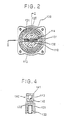
- a discharge groove 113 and a suction groove 114 are formed at the outer surface of cylindrical pump column 112 as shown in Fig. 2.
- the discharge groove 113 is formed at one surface of the column 112 and the suction groove 114 is formed at another surface of the column 112.
- the opening angle of the discharge groove 113 should be less than 180 degree, the opening angle of the discharge groove 113 of the present embodiment is about 140 degree.
- the opening angle of the suction groove 114 also should be less than 180 degree, and that of the present embodiment is about 140 degree.
- the discharge groove 113 is connected with a discharge path 115 which is formed within the pump column 112 and the end plate 111, so that high pressurized working oil is discharged toward an automotive brake system via the discharge path 115.
- the suction groove 114 is connected with the suction chamber 111 via a suction path 116 which is formed within the pump chamber 112. Since the suction chamber 101 is connected with an oil sump via a suction port which is not shown, the working oil within the oil sump is supplied to the suction groove through the suction path 116.
- a cylindrical rotor 113 is provided around the pump column 112 by a predetermined small clearance.
- a couple of cylinders 131 are formed within the rotor 130 as shown in Fig. 2 in such a manner that both of a couple of cylinders apart from each other by 180 degree.
- a piston 132 is slidably provided within the cylinder 131 by keeping slight clearance between the inner surface of the cylinder 131 and the outer surface of the piston 132.
- a spring 133 is provided within the cylinder 131 for biasing the piston 132 outwordly.
- Fig. 5 shows the first position when the first piston 132 becomes a bottom dead point, namely when the distance between the outer surface of the rotor 130 and the inner surface of the inner race 142 becomes minimize.
- the rear side end point 1314 of the opening port 1312 of the first cylinder 131 fits to the finishing point 1132 of the discharge groove 113, and there exits a first predetermined angle ⁇ 1 between the opening point 1141 of the suction groove 114 and the front end point of the opening port of the first cylinder 131.
- the inner diameter of the opening port 1312 of the present embodiment is about 3mm and the first predetermined angle ⁇ 1 of the present embodiment is about 15 degree.
- Fig. 6 shows a second position where the rotor 130 rotates by the first predetermined angle ⁇ 1 from the first position.
- the front end point 1315 of the opening port 1312 fits to the starting point 1141 of the suction groove 114, and there exists a second predetermined angle ⁇ 2 between rear end point 1316 of the opening port 1311 of the second cylinder 131 and the finishing point 1142 of the suction groove 114 as shown in Fig. 6.
- the opening port 1311 of the second cylinder 131 is connected to the suction groove 114 via the second predetermined angle 2.
- the second predetermined angle ⁇ 2 of the present embodiment is about 5 degree.
- Fig. 7 shows the third position where the rotor 130 rotates by the second predetermined angle ⁇ 2 from the second position.
- the finishing point of the suction groove 114 fits to the rear end point 1316 of the opening port 1311, and there exists a third predetermined angle ⁇ 3 between the front end point 1317 of the opening port 1311 and the starting point 1131 of the discharge groove 113 as shown in Fig. 7.
- the third predetermined of the present embodiment is about 15 degree.
- the distances between the finishing point 1132 of the discharge groove 113 and the starting point 1141 of the suction groove 114 and the finishing point 1142 of the suction groove 114 and the starting point 1131 of the discharge groove 113 are longer than the inner diameter of the opening ports 1311 and 1312 of the cylinders in order to attain the effective seals at the opening port 1311 and 1312 of the cylinders.
- a seal length of the first predetermined angle ⁇ 1 is formed at the opening port 1412, and a seal length of the third predetermined angle ⁇ 3 is formed at the another opening port 1311.
- the predetermined angles ⁇ 1 and ⁇ 3 are very important for keeping the seal around the opening ports 1312 and 1311, the predetermined angles ⁇ 1 and ⁇ 3 further have the important operation for modulating the pressure of the working fluid within the cylinder 131.
- the cylinder 132 is under discharge stroke until the opening port 1312 departs from the discharge groove as shown in Fig. 5, and the pressure of the working fluid within the cylinder under the discharge stroke is held around 100 - 200 atm. If the opening port 1312 connects to the starting point 1141 of the suction groove just after the end of the discharge stroke, the pressure of the working fluid within the cylinder reduces suddenly from the discharge pressure (100 - 200atm) to the suction pressure (1 atm), and such rapid pressure change causes an extraordinary noise and also causes the pump vibrate.
- the present pump on the other hands, has the first predetermined angle between the opening port 1312 and the starting point 1141 of the suction groove, the piston 1312 moves outwordly while the rotor rotates by the first predetermined angle ⁇ 1, so that the pressure within the cylinder 131 can reduce. In other words, the pressure within the cylinder 131 can already reduced to about the suction pressure when the opening port 1312 connects to the starting point 1141 of the suction groove 114.
- the pump of the present embodiment does not have the sudden pressure change around the starting point 1141 of the suction groove, so that the pump of the present embodiment does not vibrate.
- the opening port 1311 of the cylinder 131 still connects to the suction groove 114 even after the upper dead point of the piston 132 as shown in Fig. 5 for keeping the pressure within the cylinder 131 under suction pressure for a long while.
- the opening port 1311 passes through the finishing point 1142 of the suction groove 114 at the third position shown in Fig. 7. Since the third predetermined angle ⁇ 3 exists between the opening port 1311 and the starting point 1131 of the discharge groove 113, the working fluid within the cylinder 131 is preliminary pressurized. This preliminary pressurizing makes the pressure of the working fluid within the cylinder 131 increases from the suction pressure (1 atm) to the high pressure which is closed the discharge pressure. So that rapid pressure change is not occurred at the point where the opening port 1311 of the cylinder 131 connects to the starting point 1131 of the discharge groove 113.
- Fig. 8 shows the pressure change within the cylinders 131 in accordance with the rotational angle of the rotor 130.
- the 0 degree of the rotational angle represents the bottom dead point of the piston 132.
- the pressure within the cylinder 131 gradually increases while the third predetermined angle ⁇ 3, and gradually reduces while the first predetermined angle ⁇ 1. Both first and second cylinders 131 stay the suction pressure simultaneously by the second predetermined angle ⁇ 2.
- the top end of the piston 132 is shaped to be spherical.
- a limiting piece 134 is formed on the outer surface of the rotor 130 on the end plate 111 side.
- a couple of connecting grooves 135 are formed on the outer surface of the rotor 130 on the shaft 102 side. Each of the connecting grooves 135 aparts from the cylinder 131 by 90 degree.
- a coupling 137 is connected to a flat surface 136 formed on the end portion of the shaft 102 so that the coupling 137 rotates synchronizedly with the shaft 102.
- the coupling has a couple of connecting pieces each of which is inserted into the connecting groove 135 of the rotor 130, so that the rotation of the shaft 102 is transmitted to the rotor 130 through the coupling 137. Since the connecting piece 138 is bent perpendicularly from the coupling 137, the connecting piece 138 can limit the horizontal movement of the rotor along with the axis of the pump column 112, so that the rotor 130 is well prevented to be dropped off the pump column 112.
- a bearing 140 is provided within the suction chamber 101 in such a manner that the inner surface of the bearing 140 faces to the outer surface of the rotor 130.
- the bearing 140 has an outer race 141 which abuts to the housing 100, an inner race 141 to which the top end of the piston 132 abuts, and a number of balls 143 provided between the inner race 142 and the outer race 141.
- the sectional shape of the inner race 142 is formed to be spherical in order to fit with the top end of the piston 132. Accordingly, the top end of the piston 132 can contact with the inner race 142 via an enough wide area, so that the stress caused between the top end of the piston 132 and the inner race 142 can be reduced.
- the inner race 142 can rotate synchronizedly with the rotor 130 when the limiting pieces 134 contacts to the inner race 142, so that the relative movement between the top end of the piston 132 and the inner surface of the inner race 142 is well prevented. Furthermore, since the limiting piece 134 can contact with the inner race 142 when the rotor 130 slides along with the axis of the shaft, the rotor 130 is well prevented from dropping off the pump column 112.
- a leaf spring 146 is provided between the end plate 111 and the outer race 141 for holding the outer race 141.
- the width of the inner race 142 is narrower than that of the outer race 141, so that the working oil within the chamber can be introduced into the intermediate portion where a number of balls 143 are held. Furthermore, since the width of the inner race 142 is smaller than that of the outer race, the inner race 142 can rotate more effectively.
- the shaft 102 starts to rotate within the housing 100 when the motor 200 starts to rotate.
- the rotation of the shaft 102 is transmitted to the rotor 130 via the coupling 137, so that the rotor 130 starts to rotate on the pump column 112.
- the pump column 112 off-sets from the center axis of the bearing 140, the distance between the pump column 112 and the inner race 142 varies in accordance with the rotation of the rotor 130, so that the piston 132 reciprocates within the cylinder 131.
- the suction stroke namely while the cylinder 131 functionaliy connects to the suction groove 114, the working fluid within the suction groove 114 is sucked toward the cylinder 131.
- the piston 132 moves outwordly by the biasing force of spring 133 and the centrifugal force caused by the rotation of the rotor 130, so that the top end of the piston 132 is forced toward the inner surface of the inner race 142.
- the stress caused between the top end of the piston 132 and the inner surface of the inner race 142 during the suction stroke is much smaller than that during the discharge stroke.
- the stress during the suction stroke of the present embodiment is about 1 Kg.
- the cylinder 131 functionally connects to the discharge groove 113.
- the piston 132 is forced to be moved into the cylinder 131, so that the working fluid within the cylinder 131 is discharged toward the discharge groove 113. Since the pressure of the working fluid within the cylinder 131 increases, the piston 132 is biased toward the inner race 142 by extremely high pressure.
- the stress caused between the top end of the piston 132 and the inner surface of the inner race 142 during the discharge stroke of the present embodiment is about 100 Kg.
- the piston 132 Since the central axis of the rotor 130 is off set from the center axis of the bearing 140, the piston 132 relatively wobbles with the inner race 142, and the distance between a couple of pistons 132 along with the inner surface of the bearing 142 (designated by the reference letter A and B in Fig. 6) is valid in accordance with the rotation of the rotor 132. It should be noted that a couple of pistons 132 of the present invention do not receive the discharge pressure simultaneously. Accordingly, at least one of a couple of pistons 132 receives the suction pressure.
- the inner race 142 rotates synchronizedly with the rotation of the piston 132 by which the discharge pressure is caused, so that there should be generated the relative movement between the inner surface of the inner race 142 and the top end of the piston 132 to which suction pressure is applied.
- the stress caused between the inner race 142 and the piston to which the suction pressure is applied is small enough, no abrasion is occurred between the inner race 142 and the piston 132 to which the suction pressure is applied.
- the radial piston pump having three pistons 132 should have the condition when two of three cylinders are applied by the discharge pressure, accordingly two pistons are forced toward the inner race 142 by high pressure simultaneously. Since the distance between an adjacent two pistons 132 along with the inner surface of the inner race are valid in accordance with the rotation of the rotor 130, the top end of the two pistons to which high pressure is applied should slide against the inner race and should wear. In order to avoid the abrasion, such radial piston pump having three pistons should have shoe between the piston 132 and the inner race 142. The shoe, however, should bring such disadvantage that the shoe increases the producing cost of the pump, as described before.
- the radial piston pump of the present invention on the other hands, can well prevent the abrasion of the piston 132 and the inner race 142 because at least one of a couple of pistons 132 receive the suction pressure at any position during the rotation of the rotor 130.
- the top end of the piston 132 of the present embodiment is formed spherically, the stress caused between the top end of the piston 132 and the inner race 142 can reduces for protecting the abrasion.
Landscapes
- Engineering & Computer Science (AREA)
- Mechanical Engineering (AREA)
- General Engineering & Computer Science (AREA)
- Reciprocating Pumps (AREA)
- Valves And Accessory Devices For Braking Systems (AREA)
Applications Claiming Priority (4)
| Application Number | Priority Date | Filing Date | Title |
|---|---|---|---|
| JP4719487 | 1987-03-02 | ||
| JP47194/87 | 1987-03-02 | ||
| JP331338/87 | 1987-12-25 | ||
| JP62331338A JPS64367A (en) | 1987-03-02 | 1987-12-25 | Radial piston pump |
Publications (2)
| Publication Number | Publication Date |
|---|---|
| EP0281019A2 true EP0281019A2 (fr) | 1988-09-07 |
| EP0281019A3 EP0281019A3 (fr) | 1990-02-28 |
Family
ID=26387349
Family Applications (1)
| Application Number | Title | Priority Date | Filing Date |
|---|---|---|---|
| EP88102822A Withdrawn EP0281019A3 (fr) | 1987-03-02 | 1988-02-25 | Pompe à pistons radiaux |
Country Status (3)
| Country | Link |
|---|---|
| US (1) | US4927338A (fr) |
| EP (1) | EP0281019A3 (fr) |
| JP (1) | JPS64367A (fr) |
Families Citing this family (7)
| Publication number | Priority date | Publication date | Assignee | Title |
|---|---|---|---|---|
| JPH01244175A (ja) * | 1988-03-23 | 1989-09-28 | Nippon Denso Co Ltd | ラジアルピストンポンプ |
| US5244356A (en) * | 1990-05-23 | 1993-09-14 | Daiichi Electric Kabushiki Kaisha | Hydraulic piston apparatus |
| JP2587712Y2 (ja) * | 1992-04-27 | 1998-12-24 | 自動車機器株式会社 | ラジアルプランジャポンプのピントル固定構造 |
| GB9315342D0 (en) * | 1993-07-23 | 1993-09-08 | Lucas Ind Plc | Fuel pumping apparatus |
| US5630708A (en) * | 1993-12-28 | 1997-05-20 | Zexel Corporation | Radial piston pump for low-viscosity fuel |
| JPH08144934A (ja) * | 1994-11-25 | 1996-06-04 | Zexel Corp | 低粘性燃料用ラジアルピストンポンプ |
| FR2904380A1 (fr) * | 2006-07-26 | 2008-02-01 | Hydro Leduc Soc Par Actions Si | Perfectionnement aux pompes a barillet |
Citations (2)
| Publication number | Priority date | Publication date | Assignee | Title |
|---|---|---|---|---|
| DE1453691A1 (de) * | 1964-12-11 | 1969-05-14 | Ind Karl Marx Stadt Veb | Einrichtung zur Schmierung und Kuehlung in hydraulischen Maschinen,insbesondere Radialkolbenmaschinen |
| DE3219378A1 (de) * | 1981-05-29 | 1982-12-16 | Alfred Teves Gmbh, 6000 Frankfurt | Radialkolbenmaschine, insbesondere pumpe |
Family Cites Families (10)
| Publication number | Priority date | Publication date | Assignee | Title |
|---|---|---|---|---|
| US3188918A (en) * | 1962-04-04 | 1965-06-15 | Soya Rederi Ab | Rotary machine having a fluidworking medium |
| GB1104604A (en) * | 1965-05-05 | 1968-02-28 | Soya Rederi Ab | Improvements in hydraulic radial piston pumps and motors |
| US3345916A (en) * | 1965-11-17 | 1967-10-10 | Tobias Jaromir | High efficiency hydraulic apparatus |
| AT337004B (de) * | 1972-01-07 | 1977-06-10 | Eickmann Karl | Radialkolben-maschine - pumpe oder motor - mit stationarem oder mit rotierendem zylinderblock |
| DE3121528A1 (de) * | 1981-05-29 | 1983-01-05 | Alfred Teves Gmbh, 6000 Frankfurt | Radialkolbenmaschine, insbesondere kugelkolbenpumpe |
| JPS60182365A (ja) * | 1984-02-28 | 1985-09-17 | Nippon Denso Co Ltd | ラジアルプランジヤポンプ |
| US4652215A (en) * | 1984-04-12 | 1987-03-24 | Nippondenso Co., Ltd. | Variable capacity radial piston pump |
| US4627793A (en) * | 1984-06-13 | 1986-12-09 | Nippondenso Co., Ltd. | Motor-driven radial plunger pump |
| DE3431158A1 (de) * | 1984-08-24 | 1986-03-06 | Alfred Teves Gmbh, 6000 Frankfurt | Radialkolbenmaschine, insbesondere kugelkolbenpumpe |
| DE3780231T2 (de) * | 1986-08-09 | 1993-03-04 | Nippon Denso Co | Motorangetriebene radialkolbenpumpe. |
-
1987
- 1987-12-25 JP JP62331338A patent/JPS64367A/ja active Pending
-
1988
- 1988-02-25 EP EP88102822A patent/EP0281019A3/fr not_active Withdrawn
- 1988-02-29 US US07/162,205 patent/US4927338A/en not_active Expired - Fee Related
Patent Citations (2)
| Publication number | Priority date | Publication date | Assignee | Title |
|---|---|---|---|---|
| DE1453691A1 (de) * | 1964-12-11 | 1969-05-14 | Ind Karl Marx Stadt Veb | Einrichtung zur Schmierung und Kuehlung in hydraulischen Maschinen,insbesondere Radialkolbenmaschinen |
| DE3219378A1 (de) * | 1981-05-29 | 1982-12-16 | Alfred Teves Gmbh, 6000 Frankfurt | Radialkolbenmaschine, insbesondere pumpe |
Also Published As
| Publication number | Publication date |
|---|---|
| EP0281019A3 (fr) | 1990-02-28 |
| US4927338A (en) | 1990-05-22 |
| JPS64367A (en) | 1989-01-05 |
Similar Documents
| Publication | Publication Date | Title |
|---|---|---|
| US5626463A (en) | Axial multi-piston compressor having rotary valve for allowing residual part of compressed fluid to escape | |
| US5562425A (en) | Gas suction structure in piston type compressor | |
| US20030095873A1 (en) | Refrigeration suction mechanism for a piston type compressor and a piston type compressor | |
| US5252032A (en) | Variable capacity swash plate type compressor | |
| CA2210401C (fr) | Piston pour compresseurs | |
| EP0281019A2 (fr) | Pompe à pistons radiaux | |
| AU613893B2 (en) | Wobble plate type compressor with variable displacement mechanism | |
| EP0881386B2 (fr) | Compresseur à plateau en biais | |
| US6393964B1 (en) | Compressor having piston rotation restricting structure with lubricating inclined guide surface | |
| US6957950B2 (en) | Compressor with compact screw connected housing and adjustable mounting means | |
| US6224349B1 (en) | Reciprocating type compressor having orbiting valve plate | |
| EP0819850B1 (fr) | Piston pour compresseurs à piston | |
| US20050265855A1 (en) | Piston type compressor | |
| EP1030057B1 (fr) | Pompe ou moteur hydraulique | |
| US5004406A (en) | Radial piston pump | |
| US6371007B1 (en) | Swash plate type compressor with a lubricated shoe-and-socket piston joint | |
| US6293761B1 (en) | Variable displacement swash plate type compressor having pivot pin | |
| JP3668582B2 (ja) | アキシャルピストンポンプ | |
| US20030047066A1 (en) | Axial piston pump with rocker cam counterbalance feed | |
| EP1137881B1 (fr) | Palier de butee hydrostatique pour pompe a plateau oscillant | |
| JPH1047231A (ja) | 可変容量型圧縮機 | |
| KR100274970B1 (ko) | 가변용량형 사판식 압축기 | |
| US6257120B1 (en) | Swash plate type compressor in which a piston joint uses a rotational elliptical surface and a spherical surface opposite thereto | |
| KR100558702B1 (ko) | 가변용량 사판식 압축기 | |
| EP0947696A1 (fr) | Compresseur à plateau de commande oblique avec accomodation facile et rapide de pression en boíte de manivelle |
Legal Events
| Date | Code | Title | Description |
|---|---|---|---|
| PUAI | Public reference made under article 153(3) epc to a published international application that has entered the european phase |
Free format text: ORIGINAL CODE: 0009012 |
|
| AK | Designated contracting states |
Kind code of ref document: A2 Designated state(s): DE FR IT |
|
| PUAL | Search report despatched |
Free format text: ORIGINAL CODE: 0009013 |
|
| AK | Designated contracting states |
Kind code of ref document: A3 Designated state(s): DE FR IT |
|
| STAA | Information on the status of an ep patent application or granted ep patent |
Free format text: STATUS: THE APPLICATION IS DEEMED TO BE WITHDRAWN |
|
| 18D | Application deemed to be withdrawn |
Effective date: 19900829 |