EP0280968B1 - Formation d'objets géométriques par des mouvements de translation cumulatifs - Google Patents
Formation d'objets géométriques par des mouvements de translation cumulatifs Download PDFInfo
- Publication number
- EP0280968B1 EP0280968B1 EP88102432A EP88102432A EP0280968B1 EP 0280968 B1 EP0280968 B1 EP 0280968B1 EP 88102432 A EP88102432 A EP 88102432A EP 88102432 A EP88102432 A EP 88102432A EP 0280968 B1 EP0280968 B1 EP 0280968B1
- Authority
- EP
- European Patent Office
- Prior art keywords
- sweep
- rayset
- entry
- swell
- operational
- Prior art date
- Legal status (The legal status is an assumption and is not a legal conclusion. Google has not performed a legal analysis and makes no representation as to the accuracy of the status listed.)
- Expired - Lifetime
Links
Images


Classifications
-
- G—PHYSICS
- G06—COMPUTING; CALCULATING OR COUNTING
- G06T—IMAGE DATA PROCESSING OR GENERATION, IN GENERAL
- G06T17/00—Three dimensional [3D] modelling, e.g. data description of 3D objects
- G06T17/20—Finite element generation, e.g. wire-frame surface description, tesselation
-
- B—PERFORMING OPERATIONS; TRANSPORTING
- B29—WORKING OF PLASTICS; WORKING OF SUBSTANCES IN A PLASTIC STATE IN GENERAL
- B29C—SHAPING OR JOINING OF PLASTICS; SHAPING OF MATERIAL IN A PLASTIC STATE, NOT OTHERWISE PROVIDED FOR; AFTER-TREATMENT OF THE SHAPED PRODUCTS, e.g. REPAIRING
- B29C64/00—Additive manufacturing, i.e. manufacturing of three-dimensional [3D] objects by additive deposition, additive agglomeration or additive layering, e.g. by 3D printing, stereolithography or selective laser sintering
- B29C64/10—Processes of additive manufacturing
- B29C64/106—Processes of additive manufacturing using only liquids or viscous materials, e.g. depositing a continuous bead of viscous material
- B29C64/124—Processes of additive manufacturing using only liquids or viscous materials, e.g. depositing a continuous bead of viscous material using layers of liquid which are selectively solidified
- B29C64/129—Processes of additive manufacturing using only liquids or viscous materials, e.g. depositing a continuous bead of viscous material using layers of liquid which are selectively solidified characterised by the energy source therefor, e.g. by global irradiation combined with a mask
Definitions
- This invention relates to computer modelling for process control, and more particularly relates to computer modelling of the process of shaping a geometric object by controlled cumulative translational sweeps, according to a parameterized operational rayset, to provide a model of shaping changes to the object during the process.
- Serra states that he can "...erode a 3-D set X...with respect to a polyhedron B, by combining 2-D erosions.” Serra does not suggest using iterated sweep sequences for growing, shrinking and rounding polyhedrons. Serra develops the algebraic properties of "dilation” and "erosion” -- shaping operations based on neighborhood rules applicable over discrete domains, such as the arrangement of pixels in an image.
- Betke, U. and McMullen, P. “Estimating the size of convex bodies from projections,” J.London Math. Soc. (2), 27 (1983), pp. 525-538. shows the use of zonotopes to approximate spheres.
- Kishi et al METHOD OF CREATING A CURVED SURFACE, 1986, shows development of a curved surface in sections from section data by developing perpendicular curves for machining control.
- Shape is a generic term in geometric modelling, having many senses such as growing, shrinking, rounding, filleting, faceting, blending and smoothing. It is encountered in such applications as: growing and shrinking to solve the collision-avoidance problem; growing and shrinking for the generation of blends; sweeping to compute the shape of various space regions; and offsetting as a means of defining mechanical tolerance.
- Sweeping as a geometric modelling tool, refers in its broad sense to the tracking of a body's motion in space. Most modellers can compute the track or sweptspace of a moving body which does not tumble, i.e., which has only translational freedom; this is the region of space that the moving body has passed through, or, quite informally, its "ghost.” Some modellers can approximate tumbling motions (rotational freedom) as well.
- This patent specification describes computer modelling of the process for shaping a polyhedral model.
- This invention applies a sweep of the sweptspace of the previous sweep, cumulatively, effecting motion in not only the body but also in its ghost. If the ghost is deemed to be carried along with the body's motion and so to spawn its own ghost of a ghost (and so on, and so forth, ...), then there is a much larger sweptspace than is usually conceived -- one that we call cumulative to contrast it with the familiar tubularsweptspace. Cumulative sweeping without tumbling serves our shaping needs; we call such an operation a cumulative translational sweep or CTS.
- CTS cumulative translational sweep
- the CTS method relates to a general offsetting operation known as Minkowski summation -- and also as set convolution -- that shapes a set of points by adding (vector summing) to each of them, in all possible pairings, each of the points of another selected shaping body (which we call off setter or shaper).
- Minkowski summation -- and also as set convolution -- that shapes a set of points by adding (vector summing) to each of them, in all possible pairings, each of the points of another selected shaping body (which we call off setter or shaper).
- the effect of CTS prescriptions is to develop around any input polyhedron a polyhedral sweptspace which is the Minkowski sum of the input with a shaping polyhedron from the zonotope subfamily of the polytope family of polyhedrons.
- the object of the invention is to provide a new method for effectively and easily shaping computer models of geometric objects undergoing process dynamics.
- a feature of the invention is the technique of carrying out cumulative sweeps to provide shaping to the input polyhedral model.
- Another feature of the invention is to provide for entry of parameters including scale, balance, convexi- ty/concivity (CMODE), degree of faceting, and memory limitation.
- CMODE convexi- ty/concivity
- Another feature of the invention is to increase overall economy of computer usage by selectively reversing the ray direction if the direction-of-sweep-facecount is greater than the contra-sweep-facecount, and performing a translation operation to correct for the translation error induced by the ray reversal.
- An advantage of the invention is that complicated shaping phenomena may be modelled in terms of swells, for useful display or for direct use in controlling the shaping process tool.
- FIGs. 1-12 are composite figures illustrating the theory of the controlled cumulative translational sweeps modelling process, as follows:
- FIGs. 1-13 are demonstrative of the theory and mathematics involved in carrying out shaping operations on geometric models using controlled cumulative translational sweep (CTS) mechanism according to rayset and parameter stipulations of shape, balance, convexity/concavity (CMODE), degree of faceting and memory limitation.
- CTS cumulative translational sweep
- the controlled cumulative translational sweep is a technique for modelling the shaping of geometric objects. It may be applied, in combination with Boolean operations, to stimulate growth and shrinking over the boundary regions of polyhedral models, and thus to control such growth and shrinking. By creating additional facets, it may be used to achieve selective and global rounding effects along model edges and around model vertices. Sweeps are examined in terms of a conceptual framework that describes their effects as Minkowski sums -- of the polyhedra to be swept, with convex polyhedra from the class of mathematical objects known as zonotopes.
- the CTS system may be used for the simulation or control of semiconductor wafer fabrication, or for the simulation or control of icing on aircraft lifting or control surfaces, or for many other uses.
- FIGs. 1-13 Those who have great familiarity with the mathematics of computer modelling of geometric objects may wish to scan the theory sections and FIGs. 1-13 quickly, then read the practical general statement of the invention in the context of sections OPERATION OF THE CTS SYSTEM and STIPULATING RAYSET AND FACTORS, together with FIG. 14.
- Asweep is generally defined as any function, S, which maps a time t (of some parameter interval), a motion F(t), and a body B, to a sweptspace, S(F,t,B), that depends on both B and its motion history.
- S maps a time t (of some parameter interval), a motion F(t), and a body B, to a sweptspace, S(F,t,B), that depends on both B and its motion history.
- the trajectory, or tube, of B under sweep S is the union over all trajectory curves of points in B:
- the sweep curve is the translation curve, f, it is identifiable as the trajectory, or tube, of ⁇ 0 ⁇ -- i.e., as the image set, f([O,t]), of [O,t].
- a related subset of the sweptspace is the set S(t, ⁇ o ⁇ ), or, by understanding, S(t, 0 ); we call this set the swell. It is the swept image of singleton set, ⁇ 0 ⁇ , and for a tubular sweep it agrees with the sweep curve, but for cumulative sweeps (below) it is more extensive.
- sweep S we describe sweep S as cumulative, and say it has a memory, if the sweptspace at any time t is more extensive that the corresponding tube.
- This will be made exact by membership rules to be developed; informally, it means that points may enter a time-t sweptspace not only along point trajectories that have originated in B but also along point trajectories that have originated in earlier sweptspaces.
- An available modelling system the GDP modeller, has an algorithm that creates a polyhedral approximation, under tubular mixed sweep, for the tube of a polyhedral body.
- this algorithm makes available a precise representation for the polyhedral sweptspace that results from the tubular translational sweep of a polyhedron along a single line-segment sweep curve; and by iterating the latter process along finitely many line segments of a piecewise linear sweep curve, taking the output sweptspace from each stage (line segment) as the input body to the next, we achieve the special CTS used in OYSTER simulations.
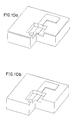
- FIG. 1 sequence, which shows the generation of an octagonal from a square prism.
- the sweep curve is seen as a simple two-segment curve in proximity to the input prism; the first curve segment prescribes a tubular sweep that develops the FIG. 1 (b) sweptspace, shown enclosing the original prism; the second segment then determines the output prism, FIG. 1 (c), as a sweep of the former result.
- TTS tubular translational sweep
- FIGs. 1 (d) indicates another way of conceptualizing the result. It shows the rays of the sweep, i.e., the separate sweep curve segments treated (and stored by OYSTER) as vectors, and the swell -- in this case a shaded parallelogram identifiable with the effect of the sweep upon a single point.
- the figure suggests how the output prism derives from the Minkowski sum of the swell and input prism -- informally, by sliding the swell around the boundary of the input prism while maintaining the swell's orientation and (with respect to the swell) the point of coincidence.
- a polytope is the convex hull of a finite set of points.
- An alternative definition of zonotope that de-emphasizes its line segment basis is that it is a centrally symmetric polytope having centrally symmetric facets of every order, where a set is centrally symmetric, or centered, if it reflects through one of its own points onto itself, in this exact sense: Xis centered at ⁇ Xif p ⁇ Ximplies segment pp' c X, where p' ⁇ 2c- p, the reflection of p through c In other words -- and this is a characterization we later employ -- X is centered at c iff for every p ⁇ Xand a ⁇ [0,2], p + a(c - p) ⁇ X.
- a rayset Starting with a rayset, one may produce the zonotope which is its associated swell by applying the rayset, as a CTS prescription, to the origin.
- the rayset To go in the reverse direction, from an initial zonotope to a rayset which generates it, one may determine rays in this manner: call the zonotope's edges equivalent if they are parallel; let one ray (directed either way, by choice) represent each such equivalence class; the rayset so determined generates a translationally congruent zonotope (its location being influenced by the direction choices made -- see discussion of ray reversal below).
- Notation S R and terms such as "swell" call attention to the underlying rays and the growth dynamic that may be associated with zonotopes. We now return to that focus -- natural to the study of sweeping as a growth process.
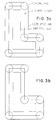
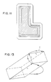
- FIG. 3 illustrates CTS rounding of an L-shaped polygon by two swells which approximate a circle, first roughly and then more accurately.
- a four element planar rayset develops the octagonal swell shown in FIG. 3(a), and an eight element one develops the sixteen sided polygonal swell FIG. 3(b).
- the results show that the L develops a cover, S R (L), that has new edges around each original convex vertex -- a simple approximation to rounding.
- the figure also illustrates the relations between swells as shapers and the grown or shrunken bodies that CTS creates.
- Output sweptspaces are shown in relation to the swells, in a manner that clarifies the Minkowski summation that is (conceptually) involved; swells seem to have acted upon input polygon L by sliding around its boundary, ⁇ L, and displacing it into a new position -- determined with respect to the original by the swell's own shape.
- inward offset lines delineate the inward extent of the tube; outward offset lines delineate the outward extent.
- the swell passes through the tube and takes a turn at a convex corner (with respect to L), it impresses a partial image of itself in the outward line, a faceted relic of its passage; along the inward offset line (growth line for L complement) the relics are left near L's concave corners; across the tube from a faceted impression the opposite tube boundary retains L's angularity, a hint that on one side the tube has completely swallowed the swell.
- hangpoint The point of the swell which always maintains coincidence with ⁇ L we call the hangpoint.
- the origin o
- this special name is an invitation to see it in terms of its relative position, at a particular boundary or interior location within the swell, and to consider this relative location as pertinent to the shape of that portion of sweptspace that lies outside the body (the incremental deposited layer).
- hangpoint and center of symmetry agree is to say that the sweep curve is closed, or that the rays sum to o.
- the simulation of rounding at the corners of L improves as the number of rays is increased.
- a planar swell may be made to approach arbitrarily closely to a circular disk.
- N rays are defined by letting r n be the ray of length IN at angle (2n - 1) ⁇ /2N (counterclockwise from the +x axis), where I N ⁇ 2 sin- 1 ( ⁇ /2N), then the swell is a 2N-gon inscribing the unit circle and inscribed by a circle of radius cos( ⁇ /2N).
- Regions corresponding to the following operational definitions may also be identified in FIG. 3:
- FIG. 4(a) shows the sweptspace after the first, gr 2R , stage.
- FIG. 4(b) shows "half-way back" and "rounded everywhere”; shrinking "all the way back" -- either from the FIG. 4(a) sweptspace using shr 2R or the FIG. 4(b) one using shr R -- creates the fill of FIG. 4(c).
- a different aim might be to round along all vertical edges of the prism while leaving the central regions of each of its faces in fixed locations -- the sequence, a simple extension of the above.
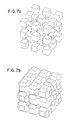
- FIG. 7(a) The input lattice, FIG. 7(a), was grown from a single point by a sequence involving three orthogonal rays, one application of grand six applications of gri; the reshaped lattice, FIG. 7(b), restates in each of its 27 repeated "modules" what the four-ray sequence does to a single cube -- or, with a slight twist, what a particular seven-ray sequence would do to a point.
- a swell, S R is known to be convex, centered, and compact (for Euclidean space, closed and bounded) -- say a 3C set.
- seg is a sausage-shaped set that covers on one end an s -neighborhood of p, E(s,p), and on the other an s-neighborhood of x, E(s,x) ⁇ r+ E(s,p). So seg is of sufficient size that every line segment parallel to r which spans its interior has length >
- the central symmetry property allows us to invert it through the center of symmetry and so exhibit as subset of the swell a simple closed curve formed of that representative and its inverted image; convexity then establishes the inclusion of the planar region inside the closed curve; and an argument based on swell heights, H R ( ⁇ ), establishes the exclusion of planar region outside it -- and so completes the swell's characterization.
- H R swell heights
- the above technique permits determination of the shape of any of its planar projections; one considers the projected planar raysets.
- L is a linear transformation and A a subset of its domain, denote by LA the image set ⁇ L(a): a E A ⁇ . Then the fact that everything is additively defined and L is linear results in this immediate conclusion:
- One at swell boundary point, w is achieved by translating by -w. It is sometimes useful to chose such boundary point w with respect to a given direction, ⁇ , as one of the boundary points at which height H R ( ⁇ ) is attained.
- FIG. 9 shows the effects described.
- a layer has been grown from a rectangular slab, FIG. 9(a), as substrate in two different ways that both use the same swell but treat it in terms of a different hangpoint.
- the effective hangpoint is taken at the swell's center of symmetry, we consider that it determines a balanced swell; it induces growth layers that have a balanced appearance, as in FIG. 9(b).
- the effective hangpoint is taken somewhat "beneath” the center of symmetry deposits occur somewhat "above” the body and we call the swell a climber -- in FIG. 9(c) the hangpoint has been placed at the swell's lower boundary, raising the developed layer to the high point shown.
- the effective hangpoint is taken above the center of symmetry we call the swell a digger.
- Every strong sum is a vertex (of S R ), and every vertex other than o is a strong sum.
- H R ( ⁇ ) formulation shows a 1 to 1 correspondence between strong sums and support planes of S R that contain exactly one (non-o) point.
- zonotope S R is the convex hull of ⁇ ô ⁇ u ⁇ strong sums ⁇ .
- OYSTER takes the designer's mask artwork and the manufacturing engineer's step-by-step description of the fabrication process as its inputs. It requires the same Boolean engine as more typical mechanical CAD/CAM applications, but must deal with more unusual shapes. In the silicon process world, the forms of materials that take shape on the wafer are continuous in layer-by-layer conforming patterns, suggestive of geological strata that flow and twist in unexpected and irregular ways. OYSTER attempts to capture the roundness of the layers and to accurately reflect their varying thicknesses, which depend upon the directional orientations of the various device elements.
- a process step that occurs repeatedly is the deposition of a new material layer upon an old.
- different methods of deposition and different material types effect distinctive layer shapes, all deposited layers do conform in shape to their underlying support.
- OYSTER achieves such new layers by applying the grow operation to a composite union of underlying layers and then Boolean differencing the result and underlying composite.
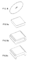
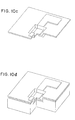
- FIG. 10 provides an example.
- Figure 10(a) shows a cut-out view of an OYSTER model, representing a device which, during its manufacture, has developed several layers.
- the fabrication step to be illustrated is a uniform coating of the device by a new blanket material layer of specific thickness.
- a union is created of all existing device components, as shown in FIG. 10(b).
- the composite union might then be swept (in the simplest case) along three orthogonal directions and a new layer then be derived by a Boolean difference which removes the composite from the swept composite, FIG. 10(c); the derived layer is shown in place, above the original layers, in FIG. 10(d).
- Square edges and corners in the layer reflect the box-shaped swell employed.
- Boolean and sweep operations illustrated in this example is typical of OYSTER algorithms which model fabrication steps.
- the mask defining the L-shaped gate region layer used in FIG. 10 can be considered a typical lithography mask shape as drawn by a device designer. Because of exposure tooling effects and material effects during the chemical development of the photoresist that has been exposed with the mask, the square corners become rounded, with a radius that is generally technology dependent.
- the CTS techniques permit us to facet around the corners and simultaneously grow or shrink the mask to compensate for fabrication effects.
- FIG. 11 shows how an appropriate combination of grow and shrink operations with the rayset of FIG. 5(a) is used to grow the original mask uniformly over the boundary while inducing faceting at both convex and concave corners.
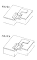
- FIG. 12 shows the effect of combining planar mask faceting and deposition faceting to achieve more realistic device shaping.
- Both masks that were used, to define the well area and the gate shape have been rounded, as may be seen in FIG. 11.
- a transmitted rounding is seen in corresponding faceted shapes in the device, as shown in FIG. 12(a).
- the well has been etched vertically downward in both figures, but the material layer beneath the gate has been deposited with one edge facet by using the rayset of FIG. 5(a).
- the L-shaped gate region has been applied in a blanket layer and vertically etched as in figure 10(a), but note that its shape, when dipping into the well, conforms to the edge faceting of the material layer below it.
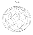
- FIG. 12(b) has been created using the same rounded masks as in FIG. 12(a) but the depositions were done with two edge facets instead of one, using a swell designed for double faceting, that of FIG. 2 . Details of rayset construction and swell hang points are made transparent to the OYSTER user, who merely selects the number of facets by setting a global parameter.
- the CTS technique is a good candidate for parallel processing, since particular "forward components" of a solid may be swept in parallel and then subjected to a summarizing Boolean union.
- FIG. 13 illustrates a curve, C, and one such parallelepiped.
- S c is the limit set of sequence SR, having taken rayset R i in association with the ith partition of [0,1] in any refinement sequence that establishes C's arclength.
- Swell-equivalence is introduced to identify curves, under this choice of equivalence relations: S1 ⁇ S 2 if swells S 1 and S 2 differ at most by translation and rotation; and C 1 ⁇ C 2 if SC 1 ⁇ SC 2 .
- ⁇ ... , (a j ,b j ), ... ⁇ may be refined by splitting into several, one or more of its members; it may be completed, extended to fully span the [0,1] domain, by adjoining each missing subinterval.
- ⁇ (0,.2),(.3,.7)> may be refined in many ways, perhaps to ⁇ (0,.1),(.1,.2),(.3,.7)>, but may be completed in only one, as ⁇ (0,.2),(.2,.3),(.3,.7),(.7,1)>.
- R is C-based with respect to an incomplete sequence and is extended by adjoining the missing rays from its completed sequence
- the extended rayset denoted by R"
- R' is based on a refinement of the domain subintervals associated with R, it is called an R refinement.
- the affine behavior is this: for a linear transformation, L, and for a translation,
- each ray r i of R may be re-expressed as a sum, over rays of R' , representative sums from S R being similarly re-expressed as belonging to S R '.
- the ⁇ -height of S c may be defined, for a unit vector ⁇ , by Hc( ⁇ ) ⁇ lub HR where the least upper bound is taken over all C-based R i . This is the total variation of function
- a limited-memory CTS having memory of duration d, may be defined with clear intuitive sense in terms of a sweep curve, C(t), that has been parameterized by arclength, say by t ⁇ [0,7]: Let d be a continuous real-valued function on [0,7], satisfying 0 ⁇ d(t) ⁇ t (for the simplest case -- memory of fixed duration -- d(t) might be min ⁇ D, t ⁇ , for some constant, D).
- C ⁇ d,s> be the segment of C defined over parameter subinterval t ⁇ [s - d(s), s].
- the CTS with memory of duration d that is defined under these circumstances is that sweep which generates as its swell,
- Swells of a limited-memory CTS lack the properties of convexity and central symmetry we have come to expect; other properties are also lost to the limited memory -- such as the permutability of curve subsegments and the expressibility of the swell as a Minkowski sum of subordinate swells associated with a curve partitioning.
- the sweep type has considerable theoretical interest -- that it may provide a conceptual tool forthinking about (even simulating) those phenomena in which temporal events may be associated with limited spatial effects.
- the richness of the constructs involved permits, for example, time-varying duration functions, d.
- FIG.14 shows the basic shaping operation using controlled cumulative translational sweeps according to a parameterized operational rayset, a stipulated operational rayset and parameters of shape, balance, convexity/concavity (CMODE), degree of faceting and memory limitation.
- the selected structuring geometric shape, a zonotope is provided at input node 1 from an external source, or from an internal source such as rayset library (RL) 2.
- the geometric object to be shaped may be provided from the same inputs, or other inputs not shown.
- Stipulations of parameter values, used for control are provided at input node 1,
- the grow-shrink decision, made by the user, is implemented by switch 3, which provides a connection for the input of the rays which determine the structuring geometric shape.
- the ray inputs pass directly via path 5 for the grow operation, in the form of a parameterized operational rayset which controls a cumulative translational sweep by CTS mechanism 4.
- a shrink operation may be selected by using switch 3 to select path 6, through Boolean complementer 7, and thence to CTS mechanism 4.
- the CTS mechanism 4 carries out a sequence of cumulative translational sweeps, one per ray of the operational rayset from rayset library 2, sweep of sweptspace of the previous sweep. Additional iterations of the sweep operation, before the final shaped geometric model is made available, are carried out by CTS mechanism 4, one for each additional ray of the rayset from input node 2. This iteration, ray by ray, is indicated graphically by broken line 13.
- the output is made available via switch 8 directly via path 9 for the grow operation (or alternatively, if the user has chosen a shrink operation, via path 10 and Boolean complementer 11) to output node 12.
- the operation is to sweep the input geometric model in accordance with the parameterized operational rayset, including stipulated parameters of scale, balance, (CMODE), degree of faceting the memory limitation.
- CMODE scale, balance,
- Each sweep is applied to the sweptspace of the previous sweep, to carry out the desired shaping operation, resulting in a reshaped geometric model.
- the lower left quadrant of FIG. 14 illustrates the technique for rayset selection with user involvement.
- the initial rayset is generated by the user or taken from an input source which may be rayset library (RL) 2.
- RL rayset library
- the rayset is modified iteratively to form an operational rayset.
- the user also accepts default parameters of scale and balance, or introduces appropriate values from keyboard 14 according to a menu prompt at terminal 15.
- the user selects for display a demonstration geometric model such as a point, line segment, rectangle or rectangular right prism.
- the reader will note that the demonstration geometric models identified are very simple forms, in series of increasing dimensional complexity. This simplicity is very useful in presenting to the user an understandable display of the result of the developing parameterized operational rayset upon the demonstration geometric model.
- the simplified demonstration geometric models are not mandatory, however.
- the user may develop a personal library of favorite geometric models
- the interim results applied to a specified demonstration geometric model are calculated and displayed on terminal 15 for acceptance or revision.
- the user may prefer to manipulate and review the rayset using default parameters of scale and balance, and then enter the actual scale and balance values. Additional dimensions beyond 3-D are available, but some creativity may be required in their display with regard to demonstration geometric models on a terminal with 2-D display.
- the user may choose one or more of the following operations:
- the CTS system then carries out the operation by calculating the controlled cumulative translational sweeps, performing shaping operations on the actual geometric model according to the parameterized operational rayset, and using the result in utilization devices such as display terminal 15, storage (S) 16 and integrated circuit process tool (T) 17.
- the inventive method is as follows:
- the scale parameters include directional scope of swell (growth, shrinkage or translation) of the operational rayset; the balance parameters include direction of layering effect; the CMODE parameters control the sequence of operations to determine whether one or both of the locally convex or concave boundary regions are to be rounded; the degree of faceting parameters trade off modelling precision for computation economy; the memory limitation parameters determine the portion of the sweptspace of the previous sweep to which the current sweep is to be applied.
- the initializing of the rayset determines the structuring geometric figure; the rayset is set to values defining a shaping polyhedron from the zonotope subfamily of polytopes. One or more of the initializing steps may be omitted if the system has been previously set with default values.
- Polyhedral modelling systems commonly include direction-of-face indicators. These indicators are used in automatic economization of resource usage by the system, by applying to each translational sweep step a decision whether to sweep forward or whether to sweep in reverse. In certain situations, the reverse sweep may be much less resource-consuming than the forward sweep.
- the reverse sweep may be much simpler than the forward sweep in that the input geometric model may have only one or a few faces in the direction of the reverse sweep, while in the direction of the forward sweep it might have many faces. Note that a reverse sweep results in a shaped body which is congruent to that of a forward sweep but translated to a different position. A translation error will be induced by reversing the sweep; such translation error will cost the overhead of a corrective retranslation.
- the overhead of the corrective retranslation is insignificant as contrasted to the savings from sweeping fewer faces.
- the overall economy of use of computational resources is greatly advantaged by investing in the small cost of corrective retranslation for the greater saving in sweep simplicity.
- the method includes canvassing direction-of-face indicators to develop a sweep-direction-facecount along the direction of sweep and to develop a contra-sweep-facecount along the opposite direction, comparing the face- counts, selectively reversing the ray direction if the direction-of-sweep facecount is greater than the contra-sweep-facecount. This results in a congruent-but-translated sweptspace.
- the saving from this simpler procedure may greatly outweigh the necessary substeps for performing a translation operation to correct for the induced translation.
- the utilization device may be a display, a storage device or a process control tool which operates in accordance with the shaped geometric model, either in open loop mode or in closed loop mode.
Landscapes
- Engineering & Computer Science (AREA)
- Physics & Mathematics (AREA)
- Materials Engineering (AREA)
- Chemical & Material Sciences (AREA)
- Theoretical Computer Science (AREA)
- General Physics & Mathematics (AREA)
- Software Systems (AREA)
- Geometry (AREA)
- Computer Graphics (AREA)
- Manufacturing & Machinery (AREA)
- Mechanical Engineering (AREA)
- Optics & Photonics (AREA)
- Image Generation (AREA)
Claims (10)
Applications Claiming Priority (2)
| Application Number | Priority Date | Filing Date | Title |
|---|---|---|---|
| US07/021,388 US4785399A (en) | 1987-03-03 | 1987-03-03 | Shaping geometric objects by cumulative translational sweeps |
| US21388 | 1987-03-03 |
Publications (3)
| Publication Number | Publication Date |
|---|---|
| EP0280968A2 EP0280968A2 (fr) | 1988-09-07 |
| EP0280968A3 EP0280968A3 (fr) | 1991-08-07 |
| EP0280968B1 true EP0280968B1 (fr) | 1994-12-07 |
Family
ID=21803908
Family Applications (1)
| Application Number | Title | Priority Date | Filing Date |
|---|---|---|---|
| EP88102432A Expired - Lifetime EP0280968B1 (fr) | 1987-03-03 | 1988-02-19 | Formation d'objets géométriques par des mouvements de translation cumulatifs |
Country Status (4)
| Country | Link |
|---|---|
| US (1) | US4785399A (fr) |
| EP (1) | EP0280968B1 (fr) |
| JP (1) | JPH077426B2 (fr) |
| DE (1) | DE3852328T2 (fr) |
Families Citing this family (70)
| Publication number | Priority date | Publication date | Assignee | Title |
|---|---|---|---|---|
| US5107419A (en) * | 1987-12-23 | 1992-04-21 | International Business Machines Corporation | Method of assigning retention and deletion criteria to electronic documents stored in an interactive information handling system |
| US5251160A (en) * | 1988-02-23 | 1993-10-05 | Evans & Sutherland Computer Corporation | System for blending surfaces in geometric modeling |
| US4888583A (en) * | 1988-03-14 | 1989-12-19 | Ligocki Terry J | Method and apparatus for rendering an image from data arranged in a constructive solid geometry format |
| ATE313105T1 (de) * | 1988-04-18 | 2005-12-15 | 3D Systems Inc | Stereolithografie mit verschiedenen vektorabtastungsmoden |
| US5776409A (en) * | 1988-04-18 | 1998-07-07 | 3D Systems, Inc. | Thermal stereolithograp using slice techniques |
| US5184307A (en) * | 1988-04-18 | 1993-02-02 | 3D Systems, Inc. | Method and apparatus for production of high resolution three-dimensional objects by stereolithography |
| US5261032A (en) * | 1988-10-03 | 1993-11-09 | Robert Rocchetti | Method for manipulation rectilinearly defined segmnts to form image shapes |
| EP0405106A3 (en) * | 1989-06-16 | 1992-04-08 | International Business Machines Corporation | Construction of minkowski sums and derivative morphological combinations of arbitrary polyhedra in cad/cam systems |
| JP2507696B2 (ja) * | 1990-09-26 | 1996-06-12 | 三菱電機株式会社 | 形状シミュレ―ション方法 |
| US5293472A (en) * | 1991-04-22 | 1994-03-08 | International Business Machines Corporation | Method of generating lines and curves of user specified thicknesses on a raster device |
| JP3153578B2 (ja) * | 1991-08-20 | 2001-04-09 | 株式会社リコー | オフセット曲面生成装置及びオフセット立体生成装置 |
| US5467443A (en) * | 1991-09-25 | 1995-11-14 | Macromedia, Inc. | System and method for automatically generating derived graphic elements |
| US5448686A (en) * | 1992-01-02 | 1995-09-05 | International Business Machines Corporation | Multi-resolution graphic representation employing at least one simplified model for interactive visualization applications |
| JP2614691B2 (ja) * | 1992-01-23 | 1997-05-28 | 旭化成工業株式会社 | 型紙の組立形状視覚化方法および装置 |
| DE4303071A1 (de) * | 1992-02-03 | 1993-10-28 | Computervision Corp | Verfahren und Vorrichtung zur Randbewertung in einer Nicht-Mannigfaltigkeits-Umgebung |
| EP0566293B1 (fr) * | 1992-04-15 | 2003-07-16 | Xerox Corporation | Procédés et systèmes d'édition et dessin graphique |
| JP3416892B2 (ja) * | 1992-06-24 | 2003-06-16 | 日本電信電話株式会社 | ブールトラジェクトソリッドサーフェス移動システム |
| JP3713055B2 (ja) * | 1992-06-24 | 2005-11-02 | 日本電信電話株式会社 | 3次元lsi形状シミュレーションシステム |
| JP3416894B2 (ja) * | 1992-06-24 | 2003-06-16 | 日本電信電話株式会社 | コンピュータ制御ディスプレイシステム |
| JP3426647B2 (ja) * | 1992-06-24 | 2003-07-14 | 日本電信電話株式会社 | 3次元トポグラフィシミュレーションのための一般化されたソリッドモデリング |
| US5379225A (en) * | 1992-06-24 | 1995-01-03 | Intel Corporation | Method for efficient calculation of vertex movement for three-dimensional topography simulation |
| US5459820A (en) * | 1992-09-10 | 1995-10-17 | General Electric Company | Method for graphical display of three-dimensional vector fields |
| US5553206A (en) * | 1993-02-12 | 1996-09-03 | International Business Machines Corporation | Method and system for producing mesh representations of objects |
| US5812435A (en) * | 1993-09-21 | 1998-09-22 | Mitsubishi Denki Kabushiki Kaisha | Shape simulation method allowing simulation of processed shape during steps of manufacturing a semiconductor device in a short period of time |
| JP2616882B2 (ja) * | 1993-12-17 | 1997-06-04 | 日本アイ・ビー・エム株式会社 | 非多様体データ構造に基づく数値制御加工シミュレーション・システム及び方法 |
| EP0757621B1 (fr) * | 1994-04-25 | 2001-11-21 | 3D Systems, Inc. | Techniques de construction ameliorees par stereolithographie |
| EP0697679A3 (fr) * | 1994-08-12 | 1998-07-01 | Dassault Systemes of America | Méthode pour dessiner par ordinateur |
| US5821941A (en) * | 1994-08-12 | 1998-10-13 | Dassault Systemes Of America, Corp. | Geometric constraints between related elements in different 2-dimensional views |
| US5615321A (en) * | 1994-08-12 | 1997-03-25 | Dassault Systemes Of America Corp. | Automatic identification of geometric relationships between elements of a computer-generated drawing |
| JP2642070B2 (ja) * | 1994-11-07 | 1997-08-20 | インターナショナル・ビジネス・マシーンズ・コーポレイション | 四角形メッシュの生成方法及びシステム |
| JPH08279446A (ja) * | 1995-04-07 | 1996-10-22 | Mitsubishi Electric Corp | 半導体装置の製造方法 |
| EP1270184B1 (fr) * | 1995-09-27 | 2005-07-06 | 3D Systems, Inc. | Modelage par dépôt sélectif de matière pour former des objets tridimensionnels |
| US5731816A (en) * | 1995-10-30 | 1998-03-24 | Ford Global Technologies, Inc. | System and method for direct modeling of fillets and draft angles |
| US5844566A (en) * | 1996-02-12 | 1998-12-01 | Dassault Systemes | Method and apparatus for controlling shadow geometry on computer displays |
| US5774111A (en) * | 1996-02-12 | 1998-06-30 | Dassault Systemes | Method and apparatus for providing a dynamically oriented compass cursor on computer displays |
| US6044306A (en) * | 1997-10-14 | 2000-03-28 | Vadim Shapiro | Methods and apparatus for shaping moving geometric shapes |
| US6243622B1 (en) * | 1998-10-16 | 2001-06-05 | Xerox Corporation | Touchable user interface using self movable robotic modules |
| US6233502B1 (en) * | 1998-10-16 | 2001-05-15 | Xerox Corporation | Fault tolerant connection system for transiently connectable modular elements |
| US6233503B1 (en) * | 1998-10-16 | 2001-05-15 | Xerox Corporation | Space filling robotic polyhedra modules |
| US6993461B1 (en) | 1999-06-10 | 2006-01-31 | Dassault Systemes | Swept volume model |
| US6870548B2 (en) | 2000-09-05 | 2005-03-22 | Mtu Aero Engines Gmbh | Method for modifying the design of a structural part |
| WO2002097735A1 (fr) * | 2001-05-31 | 2002-12-05 | Kent Ridge Digital Labs | Systeme et procede de modelisation anatomique |
| US6735556B2 (en) * | 2001-06-15 | 2004-05-11 | International Business Machines Corporation | Real-time model evaluation |
| TW580642B (en) * | 2001-08-23 | 2004-03-21 | Ulead Systems Inc | Processing method using 2-dimension graphics to draw 3-dimension objects |
| KR100427180B1 (ko) * | 2001-12-12 | 2004-04-14 | 한국전자통신연구원 | 기하도형의 모핑방법 |
| US6943810B2 (en) * | 2002-02-06 | 2005-09-13 | International Business Machines Corporation | Layered article data verification |
| US6816169B2 (en) * | 2002-10-09 | 2004-11-09 | Evans & Sutherland Computer Corporation | System and method for run-time integration of an inset geometry into a background geometry |
| US7239985B1 (en) * | 2003-09-23 | 2007-07-03 | Ncr Corporation | Methods, systems, and data structures for modeling information quality and maturity |
| US7129951B2 (en) * | 2004-05-06 | 2006-10-31 | Valve Corporation | Method and system for performing speculative collisions for a video game |
| US10258285B2 (en) | 2004-05-28 | 2019-04-16 | St. Jude Medical, Atrial Fibrillation Division, Inc. | Robotic surgical system and method for automated creation of ablation lesions |
| US10863945B2 (en) | 2004-05-28 | 2020-12-15 | St. Jude Medical, Atrial Fibrillation Division, Inc. | Robotic surgical system with contact sensing feature |
| US8755864B2 (en) | 2004-05-28 | 2014-06-17 | St. Jude Medical, Atrial Fibrillation Division, Inc. | Robotic surgical system and method for diagnostic data mapping |
| US9782130B2 (en) | 2004-05-28 | 2017-10-10 | St. Jude Medical, Atrial Fibrillation Division, Inc. | Robotic surgical system |
| US8528565B2 (en) | 2004-05-28 | 2013-09-10 | St. Jude Medical, Atrial Fibrillation Division, Inc. | Robotic surgical system and method for automated therapy delivery |
| DE102004062361A1 (de) * | 2004-12-10 | 2006-06-22 | Cocreate Software Gmbh & Co. Kg | Verfahren zur Ableitung von technischen Zeichungen aus 3D Modellen mit mindestens zwei kollidierenden 3D Körpern |
| US8155910B2 (en) | 2005-05-27 | 2012-04-10 | St. Jude Medical, Atrial Fibrillation Divison, Inc. | Robotically controlled catheter and method of its calibration |
| US7365745B2 (en) * | 2005-09-15 | 2008-04-29 | St. Jude Medical, Atrial Fibrillation Division, Inc. | Method of rendering a surface from a solid graphical image |
| US7988639B2 (en) * | 2006-05-17 | 2011-08-02 | St. Jude Medical, Atrial Fibrillation Division, Inc. | System and method for complex geometry modeling of anatomy using multiple surface models |
| US8224065B2 (en) * | 2007-01-09 | 2012-07-17 | Purdue Research Foundation | Reconstruction of shapes of objects from images |
| US7825925B2 (en) | 2007-03-09 | 2010-11-02 | St. Jude Medical, Atrial Fibrillation Division, Inc. | Method and system for repairing triangulated surface meshes |
| US8520004B2 (en) * | 2007-06-04 | 2013-08-27 | Daedal Doodle, LLC | Interactive labyrinth curve generation and applications thereof |
| EP2189918A1 (fr) | 2008-11-07 | 2010-05-26 | Dassault Systèmes | Procédé informatisé de calcul, dans un système de conception assistée par ordinateur, d'une limite d'un objet modélisé |
| US8538572B2 (en) * | 2009-06-30 | 2013-09-17 | Lam Research Corporation | Methods for constructing an optimal endpoint algorithm |
| US8983631B2 (en) | 2009-06-30 | 2015-03-17 | Lam Research Corporation | Arrangement for identifying uncontrolled events at the process module level and methods thereof |
| US8618807B2 (en) | 2009-06-30 | 2013-12-31 | Lam Research Corporation | Arrangement for identifying uncontrolled events at the process module level and methods thereof |
| US8473089B2 (en) * | 2009-06-30 | 2013-06-25 | Lam Research Corporation | Methods and apparatus for predictive preventive maintenance of processing chambers |
| US9292626B2 (en) * | 2012-12-10 | 2016-03-22 | Palo Alto Research Center Incorporated | Computer numerical control (CNC) machining tool and method for controlling a CNC machining tool |
| EP3514629A1 (fr) * | 2018-01-23 | 2019-07-24 | ASML Netherlands B.V. | Procédés et appareil pour construire un modèle géométrique paramétré d'une structure et appareil et procédé d'inspection associés |
| CN110298124B (zh) * | 2019-07-03 | 2020-10-27 | 江南大学 | 一种基于滤波的工业控制系统执行器参数估计方法 |
| CN117037959A (zh) * | 2023-07-28 | 2023-11-10 | 内蒙古工业大学 | 一种金属橡胶的细观结构建模方法、设备及存储介质 |
Family Cites Families (8)
| Publication number | Priority date | Publication date | Assignee | Title |
|---|---|---|---|---|
| US3519997A (en) * | 1961-11-13 | 1970-07-07 | Computer Graphics Inc | Planar illustration method and apparatus |
| FR1494849A (fr) * | 1966-07-21 | 1967-09-15 | Renault | Procédé de génération d'une courbe applicable à des machines à tracer ou à usiner |
| US3927948A (en) * | 1972-06-15 | 1975-12-23 | Leonard C Cox | Apparatus for producing data indicative of the geometric shape and arrangement of the various components of a model |
| US4212009A (en) * | 1977-11-16 | 1980-07-08 | Hewlett-Packard Company | Smoothing a raster display |
| US4300136A (en) * | 1979-05-10 | 1981-11-10 | Nippon Electric Co., Ltd. | Display pattern preparing system |
| JPS575109A (en) * | 1980-06-10 | 1982-01-11 | Fanuc Ltd | Curved surface forming method |
| US4454507A (en) * | 1982-01-04 | 1984-06-12 | General Electric Company | Real-time cursor generator |
| US4510616A (en) * | 1982-01-19 | 1985-04-09 | The Environmental Research Institute Of Michigan | Design rule checking using serial neighborhood processors |
-
1987
- 1987-03-03 US US07/021,388 patent/US4785399A/en not_active Expired - Fee Related
-
1988
- 1988-02-03 JP JP63022174A patent/JPH077426B2/ja not_active Expired - Lifetime
- 1988-02-19 EP EP88102432A patent/EP0280968B1/fr not_active Expired - Lifetime
- 1988-02-19 DE DE3852328T patent/DE3852328T2/de not_active Expired - Lifetime
Also Published As
| Publication number | Publication date |
|---|---|
| DE3852328T2 (de) | 1995-05-24 |
| EP0280968A3 (fr) | 1991-08-07 |
| US4785399A (en) | 1988-11-15 |
| DE3852328D1 (de) | 1995-01-19 |
| EP0280968A2 (fr) | 1988-09-07 |
| JPH077426B2 (ja) | 1995-01-30 |
| JPS63217473A (ja) | 1988-09-09 |
Similar Documents
| Publication | Publication Date | Title |
|---|---|---|
| EP0280968B1 (fr) | Formation d'objets géométriques par des mouvements de translation cumulatifs | |
| Von Herzen et al. | Accurate triangulations of deformed, intersecting surfaces | |
| CN101739494B (zh) | 在计算机辅助设计系统中计算建模对象的边界的方法 | |
| Bloomenthal | Polygonization of implicit surfaces | |
| US5038302A (en) | Method of converting continuous three-dimensional geometrical representations into discrete three-dimensional voxel-based representations within a three-dimensional voxel-based system | |
| EP1756517B1 (fr) | Systeme et procede destines a lisser une surface modifiable | |
| US6389154B1 (en) | Exact evaluation of subdivision surfaces generalizing box splines at arbitrary parameter values | |
| Kreylos et al. | On simulated annealing and the construction of linear spline approximations for scattered data | |
| Li et al. | A survey on the local refinable splines | |
| Chen | Digital Functions and Data Reconstruction | |
| Evans et al. | Shaping geometric objects by cumulative translational sweeps | |
| US7388584B2 (en) | Method and program for determining insides and outsides of boundaries | |
| US20030076319A1 (en) | Method and apparatus for encoding and decoding an object | |
| CN117115393A (zh) | 一种基于gpu的nurbs曲面并行求交方法、设备及存储介质 | |
| Chen et al. | Half-space power diagrams and discrete surface offsets | |
| Lee et al. | Polygonal boundary approximation for a 2D general sweep based on envelope and boolean operations | |
| Kumar | Interactive rendering of parametric spline surfaces | |
| Denk et al. | Truss Parametrization of Topology Optimization Results with Curve Skeletons and Meta Balls | |
| Lee et al. | Primitive geometric operations on planar algebraic curves with Gaussian approximation | |
| Ren et al. | McGrids: Monte Carlo-Driven Adaptive Grids for Iso-Surface Extraction | |
| Lienhardt et al. | Combinatorial models for topology-based geometric modeling | |
| Cohen et al. | Generating a smooth voxel-based model from an irregular polygon mesh | |
| Zou | An algorithm for triangulating 3D polygons | |
| Hamann et al. | On Simulated Annealing and the Construction of Linear Spline Approximations for Scattered Data | |
| Bushrod | Unstructured mesh generation for mesh improvement techniques and contour meshing |
Legal Events
| Date | Code | Title | Description |
|---|---|---|---|
| PUAI | Public reference made under article 153(3) epc to a published international application that has entered the european phase |
Free format text: ORIGINAL CODE: 0009012 |
|
| AK | Designated contracting states |
Kind code of ref document: A2 Designated state(s): DE FR GB |
|
| 17P | Request for examination filed |
Effective date: 19890117 |
|
| PUAL | Search report despatched |
Free format text: ORIGINAL CODE: 0009013 |
|
| AK | Designated contracting states |
Kind code of ref document: A3 Designated state(s): DE FR GB |
|
| 17Q | First examination report despatched |
Effective date: 19930322 |
|
| GRAA | (expected) grant |
Free format text: ORIGINAL CODE: 0009210 |
|
| AK | Designated contracting states |
Kind code of ref document: B1 Designated state(s): DE FR GB |
|
| REF | Corresponds to: |
Ref document number: 3852328 Country of ref document: DE Date of ref document: 19950119 |
|
| PGFP | Annual fee paid to national office [announced via postgrant information from national office to epo] |
Ref country code: GB Payment date: 19950125 Year of fee payment: 8 |
|
| PGFP | Annual fee paid to national office [announced via postgrant information from national office to epo] |
Ref country code: FR Payment date: 19950128 Year of fee payment: 8 |
|
| ET | Fr: translation filed | ||
| PLBE | No opposition filed within time limit |
Free format text: ORIGINAL CODE: 0009261 |
|
| STAA | Information on the status of an ep patent application or granted ep patent |
Free format text: STATUS: NO OPPOSITION FILED WITHIN TIME LIMIT |
|
| 26N | No opposition filed | ||
| PG25 | Lapsed in a contracting state [announced via postgrant information from national office to epo] |
Ref country code: GB Effective date: 19960219 |
|
| GBPC | Gb: european patent ceased through non-payment of renewal fee |
Effective date: 19960219 |
|
| PG25 | Lapsed in a contracting state [announced via postgrant information from national office to epo] |
Ref country code: FR Effective date: 19961031 |
|
| REG | Reference to a national code |
Ref country code: FR Ref legal event code: ST |
|
| PGFP | Annual fee paid to national office [announced via postgrant information from national office to epo] |
Ref country code: DE Payment date: 19970218 Year of fee payment: 10 |
|
| PG25 | Lapsed in a contracting state [announced via postgrant information from national office to epo] |
Ref country code: DE Free format text: LAPSE BECAUSE OF THE APPLICANT RENOUNCES Effective date: 19980218 |