EP0280480A2 - Keramische Wand und Methode zur Herstellung - Google Patents
Keramische Wand und Methode zur Herstellung Download PDFInfo
- Publication number
- EP0280480A2 EP0280480A2 EP88301436A EP88301436A EP0280480A2 EP 0280480 A2 EP0280480 A2 EP 0280480A2 EP 88301436 A EP88301436 A EP 88301436A EP 88301436 A EP88301436 A EP 88301436A EP 0280480 A2 EP0280480 A2 EP 0280480A2
- Authority
- EP
- European Patent Office
- Prior art keywords
- metal
- aluminum
- ceramic
- wall structure
- article
- Prior art date
- Legal status (The legal status is an assumption and is not a legal conclusion. Google has not performed a legal analysis and makes no representation as to the accuracy of the status listed.)
- Withdrawn
Links
- 239000000919 ceramic Substances 0.000 title claims abstract description 159
- 238000000034 method Methods 0.000 title claims description 25
- 238000004519 manufacturing process Methods 0.000 title description 18
- 229910052751 metal Inorganic materials 0.000 claims abstract description 150
- 239000002184 metal Substances 0.000 claims abstract description 150
- 229910052782 aluminium Inorganic materials 0.000 claims abstract description 110
- XAGFODPZIPBFFR-UHFFFAOYSA-N aluminium Chemical compound [Al] XAGFODPZIPBFFR-UHFFFAOYSA-N 0.000 claims abstract description 109
- 239000000463 material Substances 0.000 claims abstract description 95
- 230000007704 transition Effects 0.000 claims abstract description 90
- 239000002245 particle Substances 0.000 claims abstract description 50
- 230000004927 fusion Effects 0.000 claims abstract description 44
- 238000002485 combustion reaction Methods 0.000 claims abstract description 35
- 238000005266 casting Methods 0.000 claims abstract description 33
- 239000007789 gas Substances 0.000 claims abstract description 24
- 230000035515 penetration Effects 0.000 claims abstract description 12
- 238000000576 coating method Methods 0.000 claims description 76
- 239000011248 coating agent Substances 0.000 claims description 67
- 239000000843 powder Substances 0.000 claims description 40
- 238000005507 spraying Methods 0.000 claims description 26
- 238000007789 sealing Methods 0.000 claims description 23
- 230000004888 barrier function Effects 0.000 claims description 18
- RVTZCBVAJQQJTK-UHFFFAOYSA-N oxygen(2-);zirconium(4+) Chemical compound [O-2].[O-2].[Zr+4] RVTZCBVAJQQJTK-UHFFFAOYSA-N 0.000 claims description 17
- 239000000155 melt Substances 0.000 claims description 16
- 229910001928 zirconium oxide Inorganic materials 0.000 claims description 16
- 238000002844 melting Methods 0.000 claims description 12
- 230000008018 melting Effects 0.000 claims description 12
- 238000010438 heat treatment Methods 0.000 claims description 11
- 239000000203 mixture Substances 0.000 claims description 11
- CWYNVVGOOAEACU-UHFFFAOYSA-N Fe2+ Chemical compound [Fe+2] CWYNVVGOOAEACU-UHFFFAOYSA-N 0.000 claims description 7
- UFHFLCQGNIYNRP-UHFFFAOYSA-N Hydrogen Chemical compound [H][H] UFHFLCQGNIYNRP-UHFFFAOYSA-N 0.000 claims description 6
- 239000001257 hydrogen Substances 0.000 claims description 6
- 229910052739 hydrogen Inorganic materials 0.000 claims description 6
- TWNQGVIAIRXVLR-UHFFFAOYSA-N oxo(oxoalumanyloxy)alumane Chemical compound O=[Al]O[Al]=O TWNQGVIAIRXVLR-UHFFFAOYSA-N 0.000 claims description 6
- 229910052760 oxygen Inorganic materials 0.000 claims description 6
- QVGXLLKOCUKJST-UHFFFAOYSA-N atomic oxygen Chemical compound [O] QVGXLLKOCUKJST-UHFFFAOYSA-N 0.000 claims description 5
- 229910010293 ceramic material Inorganic materials 0.000 claims description 5
- 239000001301 oxygen Substances 0.000 claims description 5
- 239000007769 metal material Substances 0.000 claims description 4
- 239000003795 chemical substances by application Substances 0.000 claims description 3
- 230000003247 decreasing effect Effects 0.000 claims description 3
- 239000003566 sealing material Substances 0.000 claims description 3
- 239000004482 other powder Substances 0.000 claims description 2
- 238000009736 wetting Methods 0.000 claims description 2
- 150000002739 metals Chemical class 0.000 abstract description 9
- 239000011148 porous material Substances 0.000 abstract description 4
- 239000011162 core material Substances 0.000 description 42
- 239000010410 layer Substances 0.000 description 22
- VYPSYNLAJGMNEJ-UHFFFAOYSA-N Silicium dioxide Chemical group O=[Si]=O VYPSYNLAJGMNEJ-UHFFFAOYSA-N 0.000 description 21
- MCMNRKCIXSYSNV-UHFFFAOYSA-N Zirconium dioxide Chemical compound O=[Zr]=O MCMNRKCIXSYSNV-UHFFFAOYSA-N 0.000 description 16
- XKRFYHLGVUSROY-UHFFFAOYSA-N Argon Chemical compound [Ar] XKRFYHLGVUSROY-UHFFFAOYSA-N 0.000 description 8
- IJGRMHOSHXDMSA-UHFFFAOYSA-N Atomic nitrogen Chemical compound N#N IJGRMHOSHXDMSA-UHFFFAOYSA-N 0.000 description 8
- HCHKCACWOHOZIP-UHFFFAOYSA-N Zinc Chemical compound [Zn] HCHKCACWOHOZIP-UHFFFAOYSA-N 0.000 description 7
- 238000005253 cladding Methods 0.000 description 7
- 229910052725 zinc Inorganic materials 0.000 description 7
- 239000011701 zinc Substances 0.000 description 7
- 238000001000 micrograph Methods 0.000 description 6
- 238000007750 plasma spraying Methods 0.000 description 5
- XEEYBQQBJWHFJM-UHFFFAOYSA-N Iron Chemical compound [Fe] XEEYBQQBJWHFJM-UHFFFAOYSA-N 0.000 description 4
- PNEYBMLMFCGWSK-UHFFFAOYSA-N aluminium oxide Inorganic materials [O-2].[O-2].[O-2].[Al+3].[Al+3] PNEYBMLMFCGWSK-UHFFFAOYSA-N 0.000 description 4
- 229910052786 argon Inorganic materials 0.000 description 4
- 230000008859 change Effects 0.000 description 4
- 238000005336 cracking Methods 0.000 description 4
- 229910052757 nitrogen Inorganic materials 0.000 description 4
- 239000000377 silicon dioxide Substances 0.000 description 4
- 239000007921 spray Substances 0.000 description 4
- UONOETXJSWQNOL-UHFFFAOYSA-N tungsten carbide Chemical compound [W+]#[C-] UONOETXJSWQNOL-UHFFFAOYSA-N 0.000 description 4
- GWEVSGVZZGPLCZ-UHFFFAOYSA-N Titan oxide Chemical compound O=[Ti]=O GWEVSGVZZGPLCZ-UHFFFAOYSA-N 0.000 description 3
- RTAQQCXQSZGOHL-UHFFFAOYSA-N Titanium Chemical compound [Ti] RTAQQCXQSZGOHL-UHFFFAOYSA-N 0.000 description 3
- 230000015572 biosynthetic process Effects 0.000 description 3
- 238000001816 cooling Methods 0.000 description 3
- 230000000694 effects Effects 0.000 description 3
- 239000000446 fuel Substances 0.000 description 3
- 239000004576 sand Substances 0.000 description 3
- 239000000126 substance Substances 0.000 description 3
- 229910001141 Ductile iron Inorganic materials 0.000 description 2
- 229910001060 Gray iron Inorganic materials 0.000 description 2
- CPLXHLVBOLITMK-UHFFFAOYSA-N Magnesium oxide Chemical compound [Mg]=O CPLXHLVBOLITMK-UHFFFAOYSA-N 0.000 description 2
- 229910045601 alloy Inorganic materials 0.000 description 2
- 239000000956 alloy Substances 0.000 description 2
- 230000006378 damage Effects 0.000 description 2
- 230000002939 deleterious effect Effects 0.000 description 2
- 239000000835 fiber Substances 0.000 description 2
- 239000006260 foam Substances 0.000 description 2
- 239000001307 helium Substances 0.000 description 2
- 229910052734 helium Inorganic materials 0.000 description 2
- SWQJXJOGLNCZEY-UHFFFAOYSA-N helium atom Chemical compound [He] SWQJXJOGLNCZEY-UHFFFAOYSA-N 0.000 description 2
- 229910001026 inconel Inorganic materials 0.000 description 2
- 238000009413 insulation Methods 0.000 description 2
- 229910052742 iron Inorganic materials 0.000 description 2
- 239000002923 metal particle Substances 0.000 description 2
- 238000002156 mixing Methods 0.000 description 2
- 239000002365 multiple layer Substances 0.000 description 2
- 239000007787 solid Substances 0.000 description 2
- 238000004901 spalling Methods 0.000 description 2
- 239000000758 substrate Substances 0.000 description 2
- 229910052719 titanium Inorganic materials 0.000 description 2
- 239000010936 titanium Substances 0.000 description 2
- -1 vapors Substances 0.000 description 2
- 229910000967 As alloy Inorganic materials 0.000 description 1
- 229910001152 Bi alloy Inorganic materials 0.000 description 1
- 229910000640 Fe alloy Inorganic materials 0.000 description 1
- ZOKXTWBITQBERF-UHFFFAOYSA-N Molybdenum Chemical compound [Mo] ZOKXTWBITQBERF-UHFFFAOYSA-N 0.000 description 1
- 229910018487 Ni—Cr Inorganic materials 0.000 description 1
- 229910000978 Pb alloy Inorganic materials 0.000 description 1
- 235000013290 Sagittaria latifolia Nutrition 0.000 description 1
- 235000002595 Solanum tuberosum Nutrition 0.000 description 1
- 244000061456 Solanum tuberosum Species 0.000 description 1
- 229910000831 Steel Inorganic materials 0.000 description 1
- 229910001347 Stellite Inorganic materials 0.000 description 1
- NRTOMJZYCJJWKI-UHFFFAOYSA-N Titanium nitride Chemical compound [Ti]#N NRTOMJZYCJJWKI-UHFFFAOYSA-N 0.000 description 1
- QCWXUUIWCKQGHC-UHFFFAOYSA-N Zirconium Chemical compound [Zr] QCWXUUIWCKQGHC-UHFFFAOYSA-N 0.000 description 1
- 230000009471 action Effects 0.000 description 1
- 230000002411 adverse Effects 0.000 description 1
- 239000004411 aluminium Substances 0.000 description 1
- 239000010425 asbestos Substances 0.000 description 1
- 238000005422 blasting Methods 0.000 description 1
- 229910002110 ceramic alloy Inorganic materials 0.000 description 1
- AHICWQREWHDHHF-UHFFFAOYSA-N chromium;cobalt;iron;manganese;methane;molybdenum;nickel;silicon;tungsten Chemical compound C.[Si].[Cr].[Mn].[Fe].[Co].[Ni].[Mo].[W] AHICWQREWHDHHF-UHFFFAOYSA-N 0.000 description 1
- 239000010941 cobalt Substances 0.000 description 1
- 229910017052 cobalt Inorganic materials 0.000 description 1
- 235000015246 common arrowhead Nutrition 0.000 description 1
- 239000002131 composite material Substances 0.000 description 1
- 238000000151 deposition Methods 0.000 description 1
- 230000001627 detrimental effect Effects 0.000 description 1
- 238000004512 die casting Methods 0.000 description 1
- 238000009826 distribution Methods 0.000 description 1
- 230000009977 dual effect Effects 0.000 description 1
- 239000002355 dual-layer Substances 0.000 description 1
- 239000012530 fluid Substances 0.000 description 1
- 239000011521 glass Substances 0.000 description 1
- 239000011261 inert gas Substances 0.000 description 1
- 239000011133 lead Substances 0.000 description 1
- 238000003754 machining Methods 0.000 description 1
- 239000000395 magnesium oxide Substances 0.000 description 1
- 239000011159 matrix material Substances 0.000 description 1
- 230000007246 mechanism Effects 0.000 description 1
- QSHDDOUJBYECFT-UHFFFAOYSA-N mercury Chemical compound [Hg] QSHDDOUJBYECFT-UHFFFAOYSA-N 0.000 description 1
- 229910052753 mercury Inorganic materials 0.000 description 1
- 150000001247 metal acetylides Chemical class 0.000 description 1
- 229910001092 metal group alloy Inorganic materials 0.000 description 1
- 239000012768 molten material Substances 0.000 description 1
- 229910052750 molybdenum Inorganic materials 0.000 description 1
- 239000011733 molybdenum Substances 0.000 description 1
- 239000010955 niobium Substances 0.000 description 1
- GUCVJGMIXFAOAE-UHFFFAOYSA-N niobium atom Chemical compound [Nb] GUCVJGMIXFAOAE-UHFFFAOYSA-N 0.000 description 1
- 230000003647 oxidation Effects 0.000 description 1
- 238000007254 oxidation reaction Methods 0.000 description 1
- 230000000149 penetrating effect Effects 0.000 description 1
- 239000004033 plastic Substances 0.000 description 1
- 239000011347 resin Substances 0.000 description 1
- 229920005989 resin Polymers 0.000 description 1
- 229910052895 riebeckite Inorganic materials 0.000 description 1
- 238000000926 separation method Methods 0.000 description 1
- 230000009528 severe injury Effects 0.000 description 1
- 230000035939 shock Effects 0.000 description 1
- HBMJWWWQQXIZIP-UHFFFAOYSA-N silicon carbide Chemical compound [Si+]#[C-] HBMJWWWQQXIZIP-UHFFFAOYSA-N 0.000 description 1
- 229910010271 silicon carbide Inorganic materials 0.000 description 1
- 239000002356 single layer Substances 0.000 description 1
- 239000002002 slurry Substances 0.000 description 1
- 238000007711 solidification Methods 0.000 description 1
- 230000008023 solidification Effects 0.000 description 1
- 239000010959 steel Substances 0.000 description 1
- 229910052715 tantalum Inorganic materials 0.000 description 1
- GUVRBAGPIYLISA-UHFFFAOYSA-N tantalum atom Chemical compound [Ta] GUVRBAGPIYLISA-UHFFFAOYSA-N 0.000 description 1
- OGIDPMRJRNCKJF-UHFFFAOYSA-N titanium oxide Inorganic materials [Ti]=O OGIDPMRJRNCKJF-UHFFFAOYSA-N 0.000 description 1
- MTPVUVINMAGMJL-UHFFFAOYSA-N trimethyl(1,1,2,2,2-pentafluoroethyl)silane Chemical compound C[Si](C)(C)C(F)(F)C(F)(F)F MTPVUVINMAGMJL-UHFFFAOYSA-N 0.000 description 1
- WFKWXMTUELFFGS-UHFFFAOYSA-N tungsten Chemical compound [W] WFKWXMTUELFFGS-UHFFFAOYSA-N 0.000 description 1
- 229910052721 tungsten Inorganic materials 0.000 description 1
- 239000010937 tungsten Substances 0.000 description 1
- XLYOFNOQVPJJNP-UHFFFAOYSA-N water Substances O XLYOFNOQVPJJNP-UHFFFAOYSA-N 0.000 description 1
- RUDFQVOCFDJEEF-UHFFFAOYSA-N yttrium(III) oxide Inorganic materials [O-2].[O-2].[O-2].[Y+3].[Y+3] RUDFQVOCFDJEEF-UHFFFAOYSA-N 0.000 description 1
- 229910052726 zirconium Inorganic materials 0.000 description 1
Images


Classifications
-
- B—PERFORMING OPERATIONS; TRANSPORTING
- B32—LAYERED PRODUCTS
- B32B—LAYERED PRODUCTS, i.e. PRODUCTS BUILT-UP OF STRATA OF FLAT OR NON-FLAT, e.g. CELLULAR OR HONEYCOMB, FORM
- B32B15/00—Layered products comprising a layer of metal
- B32B15/04—Layered products comprising a layer of metal comprising metal as the main or only constituent of a layer, which is next to another layer of the same or of a different material
-
- F—MECHANICAL ENGINEERING; LIGHTING; HEATING; WEAPONS; BLASTING
- F02—COMBUSTION ENGINES; HOT-GAS OR COMBUSTION-PRODUCT ENGINE PLANTS
- F02F—CYLINDERS, PISTONS OR CASINGS, FOR COMBUSTION ENGINES; ARRANGEMENTS OF SEALINGS IN COMBUSTION ENGINES
- F02F7/00—Casings, e.g. crankcases
- F02F7/0085—Materials for constructing engines or their parts
- F02F7/0087—Ceramic materials
-
- B—PERFORMING OPERATIONS; TRANSPORTING
- B32—LAYERED PRODUCTS
- B32B—LAYERED PRODUCTS, i.e. PRODUCTS BUILT-UP OF STRATA OF FLAT OR NON-FLAT, e.g. CELLULAR OR HONEYCOMB, FORM
- B32B15/00—Layered products comprising a layer of metal
- B32B15/14—Layered products comprising a layer of metal next to a fibrous or filamentary layer
-
- F—MECHANICAL ENGINEERING; LIGHTING; HEATING; WEAPONS; BLASTING
- F05—INDEXING SCHEMES RELATING TO ENGINES OR PUMPS IN VARIOUS SUBCLASSES OF CLASSES F01-F04
- F05C—INDEXING SCHEME RELATING TO MATERIALS, MATERIAL PROPERTIES OR MATERIAL CHARACTERISTICS FOR MACHINES, ENGINES OR PUMPS OTHER THAN NON-POSITIVE-DISPLACEMENT MACHINES OR ENGINES
- F05C2253/00—Other material characteristics; Treatment of material
- F05C2253/16—Fibres
Definitions
- the present invention relates to articles having wall structures, particularly wall structures defining passages, in which materials of significantly different thermal expansion characteristics are securely bonded together and more particularly to the bonding materials such as carbides and ceramics to metal to provide insulated or wear passageways and the like and to the method of manufacturing such wall structures.
- the present invention particularly relates to wall structures for use in internal combustion engines, and more particularly to combustion chamber components and the passageways associated with the combustion chamber and exhaust gases therefrom and the intake thereto.
- a cylinder head either aluminum or ferrous, for example, utilizes a cast or sintered ceramic liner for insulating the exhaust port as shown in the prior art, it is difficult to obtain a good fit between the prior art ceramic liners and the casting surrounding liner to prevent leakage of exhaust gases to the cylinder head itself.
- Prior art cast liners also tend to shatter and crack under thermal and mechanical stresses associated with the casting of molten metal, manufacturing and operation of a engine. Accordingly, the application of ceramics to internal combustion engines for heat transfer barrier has been extremely limited in success.
- Patent 3,949,552 (c) utilizing a prefabricated metal sleeve fitted about a sand core or filled with core sand as a casting core, the metal sleeve having a cast layer of molten silica on the sleeve or such a layer formed by the spraying of molten silica onto the sleeve (U.S. Patents 4,148,352 and 4,077,458); casting about a sintered ceramic encased in organic fibers, and a recognition of the problems of providing a ceramic or refractory liner which is resistant to thermal and mechanical stresses encountered during casting or in engine operation (U.S.
- Patent 4,526,824 use of non-metallic composites, for example, a matrix of ceramic or glass reinforced by silicon carbide fibers to overcome the problems of low material strength and distortion which occurs when non-metallic materials are used as a component for individual combustion chamber components, the components contemplated apparently being manufactured as separate element or components for the engine (U.S. Patent No. 4,341,21).
- non-metallic composites for example, a matrix of ceramic or glass reinforced by silicon carbide fibers
- the prior art has basically utilized four types of thermal barrier designs for exhaust ports and manifolds; (1) the use of various types of coatings applied directly to passage walls of an already cast engine component utilizing a variety of ceramic materials or asbestos; (2) the use of insertable liners which are prefabricated and which are inserted into prefabricated engine parts with the liners being made of a single layer of heat resistant metal or a double layer of metal with air spaces or multiple layers of ceramic; (3) the use of cast-in-place liners which are a single metal layer or a single refractory or ceramic layer, or dual or multiple layers of metal and ceramic; (4) the use of ceramic layers cushioned by paper.
- the disadvantages of using cast-in-place ceramic liners up to the present include a lack of good bonding with the metal and the separation, poor insulation, leaks and cracking of ceramic parts caused by the variable shrinkage and solidification of cast metal around the liner and the difference in thermal expansion of the liner and metal during engine operation and/or manufacture.
- Past coatings for providing insulating linings have been of little usebecause of the fragile nature of the epitaxial bonding of the ceramic.
- Engine parts get rough treatment during manufacture including damage from machining, heat treatment, and chemical operations, any of which may cause fractures, patching and/or chipping or ceramic parts.
- severe damage of the engine is possible from chips of solid fired ceramic damaging a turbo charger, or being fed into crossovers into the intake manifold to cause damage to the piston, cylinder, piston rings and poppet valves.
- a further object of the invention is to provide new improved manufacturing methods so that hot gas passages in automotive components can be readily formed with heat barriers around the passages by the use of basically conventional casting techniques.
- the present invention contemplates the forming of a wall structure, particularly a wall structure for use at elevated temperatures such as would occur in internal combustion engines, including highly efficient engines to protect parts of the engine and systems used therewith, for example, exhaust ports and manifolds, and combustion chamber components.
- the wall structures of the present invention include a wall structure comprising a heat transfer barrier which is a zone of insulating fusion bonded ceramic particles, a transition zone between the ceramic zone and a portion of the wall structure which is substantially 100% fusion or melt bonded metal particles with the transition zone gradually chaning in percentage from substantially 100% ceramic at the ceramic zone to substantially zero percent at the substantially all metal portion with the metal gradually changing in the transition zone from substantially 100% all metal to subsequently zero percent metal at the ceramic zone.
- the present invention further contemplates such a structure in which the metal of the transition zone will be the same as or equivalent to the metal of a body portion for example the body of a cylinder head, for fusion and melt bonding purposes with the metal adjacent to the transition zone preferably being a melt of the metal of the body portion and the metal of the transition zone with the material of the ceramic zone and transition zone being fusion bonded particles.
- an article comprising a wall structure for providing a heat transfer barrier is monolithically formed by spraying molten particles of ceramic to form zones of substantially all ceramic and of substantially all metal with a transition zone in between which gradually changes between 100% ceramic and substantially zero percent metal to 100% metal and substantially zero percent metal.
- the invention further contemplates a wall structure as in the next preceding paragraph in which the transition zone terminates in an all metal zone which is melt bonded to an additional body of metal cast onto the metal zone of wall structure and a novel method of making such a structure.
- the present invention also contemplates providing wall structures, particularly wall structures for passageways, such as, a valve guide passage or an exhaust port for an internal combustion engine, where the internal portion of the passage is formed by sprayed molten particles of wear material or ceramic, and in which a wear material or ceramic zone about the passage is bonded to a part which is all metal by a transition zone which gradually changes from substantially all ceramic or wear material to substantially all metal with the particles of the wear material zone or ceramic zone being fusion bonded particles of powders of the ceramic or wear material and the transition zone being a zone formed by the spraying of a mixture of molten particles of wear material, or ceramic, and metal.
- both wear passageways and insulating passageways may be formed or manufactured by spraying of molten particles of the various materials onto a core or investment master for forming the passageways and then casting a metal body about the core of shell core for wall structures to be exposed to hot gases, such as the hot gases from a combustion chamber of an internal combustion engine.
- the ceramic zone is of a ceramic material, preferably zirconium oxide for an insulating wall structure.
- the sprayed molten particles of zirconium oxide form a heat transfer barrier with the ceramic material being preferably coated by a sealing coat of aluminum or other suitable sealing material, which may also form the wall of a passageway, for sealing the insulating ceramic against penetration of hot gases, such as are present in an exhaust system and preferably to provide a heat reflecting coating, for purposes such as providing a highly efficient engine operating at elevated combustion temperatures as compated to convential engines, or merely raising the exhaust temperatures to obtain better combustion of obnoxious components.
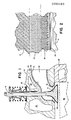
- FIG. 1 of the drawings the figure is a fragmentary showing of the cylinder head an internal combustion engine and illustrates a preferred embodiment of one aspect of my invention in the form of a wall structure for an exhaust port of a cylinder head10 of the internal combustion engine.
- the cylinder head 10 includes an exhaust port 12 and an exhaust valve 14.
- the valve 14 has a valve stem 16 and the valve cooperates with a valve seat 18 at the entrance to the exhaust port 12.
- Cylinder had 10 is shown as including conventional cooling passages 20.
- valve stem 16 extends upwardly through a conventional valve guide 22 in a passage of the cylinder head 20 to cooperate with a rocker arm not shown, for operating the valve 14.
- the valve 14 controls the connection of the exhaust port 12 to the combustion chamber 24 of the engine which, also includes a piston 26which operates in an engine block 28.
- the wall structure about the exhaust port 12 comprises a ceramic zone 30 of fusion bonded particles for providing a heat barrier about the port for reducing or minimizing the transfer of heat between the exhaust port and the cylinder head.
- the ceramic portion, part, or zone 30 blends into a zone 32 of fusion bonded ceramic and metal particles to provide a transition zone of fusion bonded particles of ceramic and metal which changes from the substantially 100% ceramic at the ceramic zone 30, to a mixture of ceramic and metal with the ceramic in the transition zone 32 gradually changing from substantially 100%to zero percent and with the metal in the transition zone gradually changing from zero percent at the ceramic zone to 100%.
- This gradual transition from ceramic to metal provides a transition or gradient zone which is strongly and monolithically bonded with the ceramic zone and with the 100% metal part of the transition zone.
- the transition zone 32 is also strongly bonded at the metal side thereof to the cylinder head body by a melt of the metal side thereof to the cylinder head body by a molt of the metal of the transition zone and the metal forming the body of the cylinder head.
- the metal at the metal side of the transition may also be fusion bonded to the metal of the cylinder head body of only a lesser bond is required or if a more convenient method of fabrication for the application.
- melt bonding is preferred in internal combustion engines where possible.
- the surface of the casting must be agressively grit blasted with, for example oxide grit, to expose metal and coating should be done immediately, so as to eliminate formation of oxides.
- the melt of the two metals penetrates the interstices of the transition zone and a monolithic structure of the metal of the cylinder head and the transition zone 32, and the ceramic zone 30 results.
- the bond of molten particles to the ceramic layer is basically a fusion bond obtained by spraying molten particles of a metal onto a solid metal article, or component.
- the ceramic zone When the metal is cast about a wall structure to provide a melt bond, the ceramic zone will form a heat transfer barrier for the heat of the cast metal, not only to assist in forming a strong melt bond between the cast metal and the metal used in the transition zone, but will prevent casting cold shuts. This assists in obtaining a good melt of casting metal and metal of the transition zone. Under circumstances in which it is not desired to insulate the casting, the cast metal could be cast directly onto a ceramic (no transition zone, etc.) for the purposes of preventing cold shuts.
- the ceramic zone 30 is preferably sealed with a coating 34.
- the sealing coating 34 is composed of aluminum with a thin skin on its exposed side of aluminum oxide when it is designed to protect the ceramic at elevated temperatures against penetration of deleterious gases, vapors, or fluids.
- the coating is formed by fusion bonding a coating of aluminum to the ceramic.
- the aluminum coating is then heated in an atmosphere of argon, helium, or nitrogen, always with hydrogen present, under pressure, for example, a pressure of at least about 2 or more atmospheres to form a melt of the aluminum and improve its penetration into the interstices of the ceramic.
- the aluminum coating will then, when exposed to heat and oxygen, preferably during the manufacturing operation, form a thin skin of aluminum oxide on the passageway surface of the alumium coating.
- This sealing coating of aluminum and alumina also functions as a heat reflecting lining for exhaust port 12 as well as providing a coating for sealing the relative porous ceramic of the ceramic zone 30 to block the penetration of hot gases which include oxygen from the exhaust port 12.
- An oxide layer should not be formed before the aluminum coating is melted in to seal the ceramic or it will intefere with the sealing of the ceramic.
- the heating in the presence of hydrogen will prevent the formation of the oxide and allow the oxide layer to be formed by heating in a hot air kiln at 1000 - 1100 C.
- the exhaust of an internal combustion engine also normally includes various corrosive of deleterious products which are detrimental to either the metal or ceramic of the wall structure of the exhaust port or both.
- Fig. 2 is a sectional enlargement of the wall structure of the port 12 to better illustrate the wall structure.
- the ceramic zone is cross-hatched to indicate that the zone is of a ceramic such as zirconium oxide of aluminum oxide.
- zirconia performs better than alumina to provide a heat transfer barrier and higher heat rejection in high temperature applications.
- the markings of X and O along various lines in the transition zone 32 of Fig. 2 generally and illustratively indicates the relative proportion of ceramic and metal along a line of the zone as the zone gradually changes from ceramic at the start of the transition zone to all metal at the end of the zone.
- the metal of zone 32 in Fig. 2 is indicated by X's and the ceramic is indicated by O's.
- the number of X's and O's along the lines of the marking in the transition zone indicate the approximate relative proportions of metal and ceramic along each line of markings.
- the horizontal dashed lines A and B of Fig. 2 indicate the general extent of the transition zone 32.
- the preferred insulating ceramic is zirconium oxide for the exhaust port 12 as well as for other components exposed to combustion or exhaust temperatures of an internal combustion engine although other ceramics whose powders may be sprayed in molten form, for example, alumina, or alumia titania might by utilized.
- the metal of the transition zone 32 is preferably the same as, or similar, or equivalent to the metal of the cylinder head or other component, for the purposes of melt bonding or plasma spraying. When a cast cylinder head is of aluminum, (casting aluminum normally contains silica), the metal of transition zone is preferably aluminum.
- the preferred metal for forming a strong monolithic bond between the transition zone and the cylinder head metal is iron, a ferrous metal.
- the transition zone preferably has iron in the initial metal of the transition and subsequently changes to the alloy being cast so that at the metal side of the transition zone it is all alloy.
- a transition zone from aluminum to ceramic is not believed to be necessary for most hot gas passageways or elevated temperatures such as present in the exhaust passage gases of internal combustion engines because of the relative thinness of the required aluminum coating, and because it is desirable to melt the aluminum into the ceramic to effect a tight seal.
- valve guide and valve seat may be feasible as a lower cost engine design to form a non-ceramic valve guide as an economy and to manufacture the valve guide and valve seat at the time of forming the insulated exhaust port. This is an economy of manufacturing, and to provide better concentricity between the valve guide and valve seat.
- the aluminum sealing coat and ceramic do have juncture which is more in the nature of a boundary than the transition zone and the ceramic or metal but it will also be noted that the metal of the coating penetrates into the interstices of the ceramic zone so that there is no singular bound line.
- the ceramic zone has a thickness of preferably from about .005inches to about .010 inch thick while the transition zone thickness is preferably about .005 inches to about .06 inches but larger if needed.
- the minimum desired porosity of the ceramic is at least 20% and preferably about 30-35%. If the insulating wall structure of the present invention is used with parts of an engine or exhaust systems where the wall structure is to be both insulating and wear resistant, or strengthened, the density of the ceramic zone may be increased so that the zone has a lower porosity as a trade-off between insulation and wear-resistance, or strength characteristics.
- the thickness of the ceramic zone will depend upon the heat barrier characteristics of the ceramic used as well as the temperature gradient desired across the ceramic zone.
- the thickness of the transition zone also depends in part upon the metals and ceramics being used, particularly, the relative coefficients of thermal expansion of the ceramic and the metals in the transition zone and the article body. In each case, the proper thickness may be determined empirically to provide the necessary characteristics for the monolithic wall structure desired. It has been found that the transition zone, between a ceramic layer and a metal layer, of between about .020 inch to about .050 inch is normally sufficient for engine exhaust systems.
- the coating need only be sufficiently thick to form a coating with a good bond to the ceramic and in the case of porous ceramics used at elevated temperatures, the sealing coat has preferably an oxide skin on the surface of the metal.
- the total thickness of an aluminum sealing coat for the exhaust port 12 and other applications requiring such a sealing coat may be for from about .003 inch to about .015 inch with the outer skin of alumina being about 2-4 microns thick.
- valve stem guide of figure 1 is illustrated as being a conventional valve guide.
- this valve guide may be formed by the proper spraying of molten particles of metal and a wear material.
- the metal and wear material molten particles may be sprayed during the formation of the wall structure for the exhaust port.
- the valve seat for the valve may also be formed at the same time as the exhuast port and may comprise an impact resistance metal such as alloy steel, Inconel, or Stellite.
- the wear coating for example, may be tungsten carbide or a tungsten carbide-cobalt lining, or a ceramic formed by plasma spraying, or a chemical vapor deposit or titanium carbide, titanium carbo-nitride or titanium nitride.
- various other valve guides of an engine can be formed in the same manner as the valve guide for the exhaust port 12.
- valve guide or a port for example, a cold air intake port
- the valve guide may be formed with a ceramic thermal barrier as in the case of the exhaust port.
- the valve guide for the exhaust valves normally will not be provided with such a thermal barrier since it is often desirable to allow the valve guide to transfer heat which may be transmitted along the valve stem to the cylinder head and cooling system.
- an insulating porting may be used as part of the wall structure for the air intake valve guide if needed.
- the insulating ceramic lining and the transition zone can be formed on a prefabricated cylinder head by plasma spraying 100% metal on the surface of a preformed wall, e.g., of a cylinder head exhaust port, starting with 100% metal, continuing into a transition zone to gradually gradient to 100% ceramic and zero percent metal, and continuing with the ceramic zone until the necessary thickness is applied. If the sealing or reflective coating is also used it is then sprayed and may utilize a ceramic to aluminum transition zone if desired. This wall structure will be fusion bonded between the sprayed metal and the metal of the cylinder head and the transition zone will monolithicaly blend into the 100% ceramic insulating zone.
- the cylinder head passage for a valve liner can be formed on a prefabricated cylinder head by first spraying molten particles of a metal which is similar or the same as the cylinder metal for fusing or binding purposes onto the passage wall of the prefabricated cylinder head, continuing to spray molten metal and wear material powders, e.g., tungsten carbide powders, to form a transition zone in which the powder sprayed changes from 100% metal to 100% tungsten carbide or other wear surface material and then continuing with solely molten wear material until the wear portion is completed.
- molten metal and wear material powders e.g., tungsten carbide powders
- an aluminum coating is initially formed by plasma spraying a coating of molten aluminum particles onto a sand core or investment masters of a different material such as wax, zinc or dipped-dried ceramic shells to provide a fusion bonded coating on the core.
- a sand core or investment masters of a different material such as wax, zinc or dipped-dried ceramic shells.
- Such an aluminum coating has been found to provide a sealing coating for a sand core which minimizes the penetration of moisture into the sand core after curing so that the core will have a longer shelf life as well as more self integrity and much higher strength.
- the sand cores contemplated may be conventional cores of resin bonded sand or other types of conventional sand cores or investment masters.
- the spraying of molten particles may be done with a spraying plasma gun.
- molten ceramic powders are sprayed to form the ceramic zone 30 and then molten ceramic and metal powders are sprayed to form the transition zone 32 from ceramic to metal.
- a thin coating of powders having one ratio of ceramic to metal is sprayed followed by the spraying in a continuous manner of successive thin coatings of different ratios until the transition is complete from all of one material to all of the other.
- the method may be performed by hand with the various ratios of powders premixed and in various hoppers, or mixing may be controlled at the gun or elsewhere using a propositional feed mechanism.
- the spraying may also be done by mounting the core, shell core, or investment master in a machine and holders where the spray gun and core, shell core or investment master are supported for relative movement having components along the horizontal, vertical and angular axes.
- powders may be introduced in to the plasma stream of the gun in the correct proportions.
- the conventional guns use a shielding gas of argon or nitrogen for the plasma stream. This is desirable to protect against oxidation.
- the cores used to manufacture a wall structure embodying the present invention need not be a sand core but may be an investment master for zinc or aluminum die casting, or wax, or cores of foam (plastic), of foam plus a dip slurry which is of silica or ceramic, lead or bismuth alloy, wax, or frozen mercury.
- a zinc investment master is preferably used as an alternative to a sand core. Such a zinc investment master is illustrated in Figure 3.
- FIG. 3 the Figure illustrates a core 40 for use in casting the exhaust port 12 and a valve guide 22 into a cylinder head, the valve guide to be comprised of fusion bonded particles of a carbide wear material.
- the core 40 is provided with a portion 42 forming the cylinder head passage for the valve stem 10 and wear guide 22 and a main body portion 44 for the exhaust port 12 and the valve seat 18.
- the core is also provided with chucking portions 48,49 to enable the core to be chucked onto a rotating table for rotating the core about axis during the spraying of the core with molten particles to form the wall structures to be incorporated into a cast cylinder head.
- the spraying may be done by hand or with a spray gun which is movable in a cross axis feed and a longitudinal feed and is mounted for universal angular movement.
- an aluminum coating 34 is first applied to the investment master in the same manner as described for the sand core to ultimately provide the wall surface for a passage, e.g., the exhaust port of a cylinder head.
- the investment master has been designated by the reference numeral 40 and the plasma sprayed aluminum coating has been designated by the reference numeral 34 and is shown as covering the whole core.
- the aluminum molten particles sprayed by the gun may gradually change from 100% metal to 100% ceramic to form a transition zone, if desired.
- a transition zone is not believed necessary between the aluminum seal coating and the insulating ceramic zone and the spraying may be changed directly from aluminum to molten particles of ceramic. These are then sprayed in successive passes to form the insulating zone 30 as the insulating lining for the exhaust port. After the desired thickness of insulating lining for exhaust port. After the desired thickness of insulating ceramic has been deposited, the molten powders are then changed to a mixture or ceramic and metal to form the transition zone in successive passes by forming a thin layer with each pass. The percentage of ceramic particles gradually decrease and the percentage of aluminum particles gradually increase as the transition zone is formed. Preferably, each pass deposits a coating of about .0005 inch to .010 thick and the percentage is incremented with each layer. After the transition zone is formed and the powders sprayed are 100% metal, the spraying is continued to provide a fusion bonded cladding zone about the transition and ceramic zone of from about at least .005 inch to about 0.05 inch thick.
- the zones of various materials are formed by successively depositing thin layers, for example, layers of .0005 to .010 inch thick, to form the zone.
- the proportion of the mixture of ceramic and metal for example, may be incremented after each or multiple passes, depending on the thickness deposited by each pass and the strength of bond needed. The stronger the bond required, or the greater the difference in coefficients of expansion between the materials to be joined, or other problems, the proportions may be incremented so that the proportions will change less for each increment, of one pass or more, from as low as 1% change per pass to 25% change per pass.
- Molten material or metallic/ceramic powders for forming the valve seat may also be applied as part of the wall structure on the core.
- the powders for the valve seat 18, which may be formed of molten particles of Inconel or other high temperature metal alloys are sprayed directly onto the aluminum coating of the core and a transition zone 39 between the valve seat material and the ceramic layer 30 is provided, as illustrated in Fig. 3A, to form the valve seat for the exhaust port.
- the valve guide wall structure is similarly formed on the core or investment master as a continuous part of the operation. In Fig. 3, the investment master valve guide portion is designated by the reference numeral 42.
- particles of tungsten carbide or other wear coating material are sprayed on the aluminium coating, as a continuation of the coating of ceramic for the exhaust port, to form the wear zone 30a on the aluminum coating 34, see Fig. 5, followed by a transition zone 32a, which is sprayed as a continuation of the transition zone 32 and makes a gradual transition between the wear guide coating and aluminum so as to provide a cladding 38 of aluminum for melt bonding with the cast aluminum cylinder head.
- the cladding of aluminum for the exhaust port wall structure, as well as the transition zone, the ceramic zone and the aluminum coatings on the core extend to the part of the investment master for forming the passageway for the valve guide and the valve guide wall material cladding zone of metal forms a continuation of the same zone for the exhaust port passage.
- These coatings when terminating will be fusion bonded to the adjacent layers as a result of the spraying of molten particles of the respective coatings and the spraying of the powders may include a transition between the powder for the exhaust port and the respective powders of the valve guide if these differ sufficiently in their coefficients of thermal expansion.
- the core or investment master is then melted, if of the type, for example, a zinc investment master, which is to be melted to provide a shell core for the casting of the aluminum cylinder head to surround the core.
- a zinc investment master which is to be melted to provide a shell core for the casting of the aluminum cylinder head to surround the core.
- the melting of the investment master may be done simultaneously with the heat treatment.
- the core or shell core After the core or shell core is ready for casting, it is incorporated into the body of the cylinder head by casting.
- the outer cladding of aluminum of the core or shell core will be melted by the molten aluminum being cast and the subsequent cast cylinder head will have a melt of the cast aluminum and the sprayed outer aluminum cladding which penetrates into the transition zone layer to form a strong bond between the particles of the transition zone and the aluminum body of the cylinder head.
- the melt may penetrate into the ceramic or wear area of the transition zone as has been determined by taking micrographs and chemical analysis of the aluminum casting in the transition zone. There will not be a definitive bond line between the outer cladding and the cast metal or with the transition zone.
- the transition zone itself will gradually blend into the melt of these materials with the melt having penetrated into the transition zone. Similarly, there is no defined boundary between the transition zone and the wear or ceramic material the adjacent zone.
- the aluminum coating which forms the wall surface of the passageway and the ceramic or wear material lining will have a more limited boundary. However, this boundary is of fusion bonded particles with the aluminum particles penetrating into the ceramic zone and pores therein, as described above to provide a relatively strong bond.
- Prior to casting about the core investment master it will have been treated as described to melt the aluminum to seal the porosity of the ceramic. Tests have been made with the core heated in an argon, nitrogen or helium atmosphere for from about 2 to about 4 hours at a temperature of 1200° Fahrenheit prior to casting. This is sufficient to effect a melt of the coating 34 into the interstices of the ceramic lining to strengthen the bond between the ceramic and the aluminum and to better seal the relatively porous ceramic from the hot gases.
- the aluminum sealing coat will maintain its integrity during this heating with the melting of the zinc investment master even though the heating is at a temperature near the melting point of aluminum because of mechanical bonding due to adhesion and surface tension.
- zirconium oxide is the preferred insulating ceramic
- other ceramics for example, aluminum oxide, titanium oxide, magnesia/zirconate and other oxides may be utilized.
- the seal coating of aluminum may be eliminated except as it is desirable to seal the core or investment master.
- the aluminum coating provides a good coating for receiving sprayed molten particles of ceramic or wear material as compared to sand and various other core materials which are conventionally utilized in casting.
- an aluminum sealing coat may be generally used to protect materials of structures against the action of and/or penetration by various agents and may also be applied to preformed structures if the structures will bond or can be prepared to bond with molten sprayed particles of aluminum.
- a metal wall may be protected by aggressively abrading its surface as by grit blasting to provide a roughened surface with voids and plasma sprayed molten particles which form a bond therewith which can be strengthened by heat treating as described.
- the applications described may utilize a heating in the argon or nitrogen or both inert atmospheres with hydrogen added to act as a getter for oxygen for from about 2 to 4 hours, the heating for other applications may require longer periods.
- the time periods for forming the aluminum oxide may vary.
- over the material being protected may be a porous material such as molybdenum or a titanate.
- aluminum has been used as the sealing material
- other sealing metals may be zirconium with a subsequent skin or zirconium oxide, titanium, tantalum, columbium or other metals which will form an oxide after beingmelted in hydrogen and an inert gas.
- the melting points of these materials are much higher than aluminum and the forming of the initial fusion bond as well as the oxide is, accordingly, more difficult to handle and apply because of the higher temperatures involved.
- Fig. 7 is a micrograph of a bond in accordance with the invention, between aluminum as coating 34 and zirconia. The micrograph also illustrates the desired porosity.
- Fig. 7 is a micrograph of a bond in accordance with the invention, between aluminum as coating 34 and zirconia. The micrograph also illustrates the desired porosity.
- Fig. 7 the aluminum is the white area at the interface (left side) of the ceramic 30.
- Fig. 8 is a scanning electron map of aluminum A distribution at 400 X showing the penetration of the aluminum 30 (white) into the zirconia and the sealing of the surface the pores (the white specks in the black and the black specks in the white in the micrograph are electron scatter).
- the zirconia has 7% yttria.
- the material is a zirconia, Ni-Cr transition in accordance with the invention and shows structure earlier described which is typical of the structure of coatings utilizing the present invention.
- fusion bonded particles is intended to describe particles which are bonded together as in plasma spraying where surface portions of the particles are molten although the centers thereof are not truly melted
- Melt bonded means a metal which has formed a bond with another material after being completely melted or is between two metals where both metals have been melted to form a melt of the metals in making the bond. It will be further understood that the transition in the applications described will normally have a limited extent which is all metal at the metal side of the zone.
- Figs. 2 and 4 are diagrammatic in the sense that the nature of the penetration of the materials of one zone or coating as described is not completely illustrated.
- the invention provides an article comprising a fusion bonded wall structure having separated first and second parts or zones of fusion bonded materials of types having significantly different coefficients of thermal expansion, e.g., a metal part or zone and a ceramic part or zone, and a transition zone fusion bonded with and between the two, the transition zone of fusion bonded particles being substantially 100% of the material of the first part at the first part and gradually changing substantially none of the material of the first part to substantially 100% of the material of the second part whereby said transition zone gradients from substantially none of said second material at said first part to substantially 100% of said second material.
- the invention further provides a method for forming a wall structure of an article for use at high temperatures such as occurs in the combustion chambers and cylinder heads of internal combustion engines comprised of zones of different type materials having widely different coefficients of expansion, one of material usually being a metal and the other a ceramic to provide a heat barrier with the wall structure comprising a first wall portion or zone of one fusion bonded to a second wall portion or zone of a different material having a widely different coefficient of expansion by a transition zone comprised of both materials, which method comprises the steps of first forming one of the wall portion of zones by spraying molten powders of one of the different type materials onto a substrate or wall surface of a body, for example on a core, shell core, or cylinder head surface, to form one of the wall portions by the fusion bonding of the material sprayed and then forming the transition zone by spraying a mixture of molten powders of the first sprayed powder and the the powder of the other type of material onto the first formed portion or zone beginning with substantially 100% of the first
- the invention provides a structure of a material having a melting point over about 1500° F sealed against contact with a particular agent to which the material may be exposed and a method of sealing the structure which comprises the steps of providing the structure to be sealed with a surface having a thin coating of aluminum particles fusion bonded to said material of the structure, heating the aluminum on the structure to cause the aluminum to wet the material adjacent the inner side of said aluminum to wet the material adjacent the inner side of said aluminum coating by heating the structure with the fusion bonded aluminum coating thereon in an inert atmosphere including hydrogen thereon at a temperature sufficient to cause the melting of the aluminum and the wetting of said material so as to obtain a mechanical bond between the material and aluminum coating, removing the structure with the coating thereon and exposing the outer side of the aluminum coating to heat and oxygen to form an oxide skin on the outer side thereof.
Landscapes
- Engineering & Computer Science (AREA)
- Chemical & Material Sciences (AREA)
- Ceramic Engineering (AREA)
- Combustion & Propulsion (AREA)
- Mechanical Engineering (AREA)
- General Engineering & Computer Science (AREA)
- Coating By Spraying Or Casting (AREA)
- Cylinder Crankcases Of Internal Combustion Engines (AREA)
- Ceramic Products (AREA)
- Molds, Cores, And Manufacturing Methods Thereof (AREA)
Applications Claiming Priority (2)
| Application Number | Priority Date | Filing Date | Title |
|---|---|---|---|
| US1822687A | 1987-02-24 | 1987-02-24 | |
| US18226 | 1987-02-24 |
Publications (2)
| Publication Number | Publication Date |
|---|---|
| EP0280480A2 true EP0280480A2 (de) | 1988-08-31 |
| EP0280480A3 EP0280480A3 (de) | 1989-06-28 |
Family
ID=21786878
Family Applications (1)
| Application Number | Title | Priority Date | Filing Date |
|---|---|---|---|
| EP88301436A Withdrawn EP0280480A3 (de) | 1987-02-24 | 1988-02-19 | Keramische Wand und Methode zur Herstellung |
Country Status (4)
| Country | Link |
|---|---|
| EP (1) | EP0280480A3 (de) |
| JP (1) | JPS63303673A (de) |
| KR (1) | KR880009789A (de) |
| BR (1) | BR8800747A (de) |
Cited By (7)
| Publication number | Priority date | Publication date | Assignee | Title |
|---|---|---|---|---|
| DE4102358A1 (de) * | 1991-01-26 | 1992-07-30 | Volkswagen Ag | Im druckgussverfahren herzustellendes formteil, verfahren zur herstellung des formteils sowie hohlkoerper zur einlage in das formteil |
| DE10121861A1 (de) * | 2001-05-05 | 2002-11-14 | Vaw Ver Aluminium Werke Ag | Aus Leichtmetallwerkstoff gegossenes Motorelement und Verstärkungselement |
| US20080011976A1 (en) * | 2006-07-17 | 2008-01-17 | Richard Brendon Scarlin | Steam Inlet Valve of a Steam Turbine |
| DE102007026123A1 (de) * | 2007-06-05 | 2008-12-11 | Volkswagen Ag | Zylinderkopf einer Brennkraftmaschine |
| WO2009086187A3 (en) * | 2007-12-21 | 2009-12-30 | Green Partners Technology Holdings Gmbh | Piston engine systems and methods |
| DE102011114771A1 (de) * | 2011-10-01 | 2013-04-04 | Volkswagen Aktiengesellschaft | Zylinderkopf mit einem integrierten Abgaskrümmer für eine Brennkraftmaschine und Verfahren zur Herstellung eines Gussbauteils, insbesondere eines Zylinderkopfs für eine Brennkraftmaschine |
| WO2025141159A1 (de) * | 2023-12-28 | 2025-07-03 | Gs Valve Engineering Gmbh | Schnellentlüftungsventil, insbesondere für eine dampfschälanlage |
Family Cites Families (4)
| Publication number | Priority date | Publication date | Assignee | Title |
|---|---|---|---|---|
| US2075388A (en) * | 1934-01-25 | 1937-03-30 | Cloud Joseph Poissant De | Heat insulating metal body |
| JPS5966966A (ja) * | 1982-10-09 | 1984-04-16 | Toyota Motor Corp | 耐熱性軽合金部材およびその製造方法 |
| US4608321A (en) * | 1984-02-20 | 1986-08-26 | Ngk Spark Plug Co., Ltd. | Ceramic and metal composite body |
| DE3444406A1 (de) * | 1984-12-05 | 1986-06-05 | Kolbenschmidt AG, 7107 Neckarsulm | Gegossene bauteile fuer brennkraftmaschinen mit eingegossenen bewehrungskoerpern sowie verfahren zur herstellung der verbindung zwischen den bauteilen und den bewehrungskoerpern |
-
1988
- 1988-02-19 EP EP88301436A patent/EP0280480A3/de not_active Withdrawn
- 1988-02-23 BR BR8800747A patent/BR8800747A/pt unknown
- 1988-02-24 KR KR1019880002016A patent/KR880009789A/ko not_active Withdrawn
- 1988-02-24 JP JP63041782A patent/JPS63303673A/ja active Pending
Cited By (11)
| Publication number | Priority date | Publication date | Assignee | Title |
|---|---|---|---|---|
| DE4102358A1 (de) * | 1991-01-26 | 1992-07-30 | Volkswagen Ag | Im druckgussverfahren herzustellendes formteil, verfahren zur herstellung des formteils sowie hohlkoerper zur einlage in das formteil |
| DE4102358C2 (de) * | 1991-01-26 | 2000-05-11 | Volkswagen Ag | Im Druckgußverfahren herzustellendes Formteil, Verfahren zur Herstellung des Formteils sowie Hohlkörper zur Einlage in das Formteil |
| DE10121861A1 (de) * | 2001-05-05 | 2002-11-14 | Vaw Ver Aluminium Werke Ag | Aus Leichtmetallwerkstoff gegossenes Motorelement und Verstärkungselement |
| DE10121861B4 (de) * | 2001-05-05 | 2005-02-17 | Hydro Aluminium Deutschland Gmbh | Aus Leichtmetallwerkstoff gegossenes Motorelement und Verstärkungselement |
| US20080011976A1 (en) * | 2006-07-17 | 2008-01-17 | Richard Brendon Scarlin | Steam Inlet Valve of a Steam Turbine |
| DE102007026123A1 (de) * | 2007-06-05 | 2008-12-11 | Volkswagen Ag | Zylinderkopf einer Brennkraftmaschine |
| DE102007026123B4 (de) * | 2007-06-05 | 2017-12-21 | Volkswagen Ag | Zylinderkopf einer Brennkraftmaschine |
| WO2009086187A3 (en) * | 2007-12-21 | 2009-12-30 | Green Partners Technology Holdings Gmbh | Piston engine systems and methods |
| DE102011114771A1 (de) * | 2011-10-01 | 2013-04-04 | Volkswagen Aktiengesellschaft | Zylinderkopf mit einem integrierten Abgaskrümmer für eine Brennkraftmaschine und Verfahren zur Herstellung eines Gussbauteils, insbesondere eines Zylinderkopfs für eine Brennkraftmaschine |
| EP2761157A2 (de) * | 2011-10-01 | 2014-08-06 | Volkswagen Aktiengesellschaft | Zylinderkopf mit einem integrierten abgaskrümmer für eine brennkraftmaschine und verfahren zur herstellung eines gussbauteils, insbesondere eines zylinderkopfs für eine brennkraftmaschine |
| WO2025141159A1 (de) * | 2023-12-28 | 2025-07-03 | Gs Valve Engineering Gmbh | Schnellentlüftungsventil, insbesondere für eine dampfschälanlage |
Also Published As
| Publication number | Publication date |
|---|---|
| BR8800747A (pt) | 1988-10-04 |
| JPS63303673A (ja) | 1988-12-12 |
| KR880009789A (ko) | 1988-10-05 |
| EP0280480A3 (de) | 1989-06-28 |
Similar Documents
| Publication | Publication Date | Title |
|---|---|---|
| US4798770A (en) | Heat resisting and insulating light alloy articles and method of manufacture | |
| EP0663020B1 (de) | Keramisch zusammengesetztes Beschichtungsmaterial | |
| EP0110064B1 (de) | Gegenstand aus einer wärmebeständigen Leichtmetallegierung und Verfahren zu seiner Herstellung | |
| EP0066022B1 (de) | Maschinenteile | |
| US5137789A (en) | Composite ceramic and metal article | |
| EP1044946B1 (de) | Silizium enthaltendes Substrat mit Calciumaluminiumsilikat-Wärmedämmschicht | |
| EP0051300B1 (de) | Verfahren zur Herstellung eines Auslassventiles für einen Dieselmotor | |
| RU2313422C2 (ru) | Способ изготовления форсунки для топливного клапана в дизельном двигателе и форсунка | |
| US5263530A (en) | Method of making a composite casting | |
| CA2229457A1 (en) | Ceramic liner infiltrated with pre-ceramic polymer resin | |
| DK151074B (da) | Sammensat metallisk isolationskomponent til forbraendingsmotorer | |
| EP0280480A2 (de) | Keramische Wand und Methode zur Herstellung | |
| CN105555728A (zh) | 搪瓷粉、具有搪瓷涂层表面区段的金属构件及其制造方法 | |
| EP0935010B1 (de) | Thermische Sperrschichtsysteme mit keramischem Gradient-Überzug | |
| GB2130244A (en) | Forming coatings by hot isostatic compaction | |
| GB2100621A (en) | Strain tolerant thermal barrier coatings | |
| JPH0527706B2 (de) | ||
| US6470550B1 (en) | Methods of making tooling to be used in high temperature casting and molding | |
| JPH028894B2 (de) | ||
| JP2920004B2 (ja) | セラミックスと金属の鋳ぐるみ複合体 | |
| JPS63157741A (ja) | 連続鋳造用鋳型 | |
| US20030106198A1 (en) | Methods of making wear resistant tooling systems to be used in high temperature casting and molding | |
| EP0191008B1 (de) | Hülsen- oder rohrförmiger Gegenstand und Verfahren zu seiner Herstellung | |
| JPS6224178B2 (de) | ||
| JPS63161150A (ja) | 断熱溶射層の形成方法 |
Legal Events
| Date | Code | Title | Description |
|---|---|---|---|
| PUAI | Public reference made under article 153(3) epc to a published international application that has entered the european phase |
Free format text: ORIGINAL CODE: 0009012 |
|
| AK | Designated contracting states |
Kind code of ref document: A2 Designated state(s): AT BE CH DE ES FR GB IT LI LU SE |
|
| PUAL | Search report despatched |
Free format text: ORIGINAL CODE: 0009013 |
|
| AK | Designated contracting states |
Kind code of ref document: A3 Designated state(s): AT BE CH DE ES FR GB IT LI LU SE |
|
| STAA | Information on the status of an ep patent application or granted ep patent |
Free format text: STATUS: THE APPLICATION IS DEEMED TO BE WITHDRAWN |
|
| 18D | Application deemed to be withdrawn |
Effective date: 19891229 |