EP0280326A2 - System und Verfahren zur mehrfachen Ausnutzung eines Floppy-disk Kontrollers für verschiedene Floppy-disk geräte - Google Patents
System und Verfahren zur mehrfachen Ausnutzung eines Floppy-disk Kontrollers für verschiedene Floppy-disk geräte Download PDFInfo
- Publication number
- EP0280326A2 EP0280326A2 EP88102915A EP88102915A EP0280326A2 EP 0280326 A2 EP0280326 A2 EP 0280326A2 EP 88102915 A EP88102915 A EP 88102915A EP 88102915 A EP88102915 A EP 88102915A EP 0280326 A2 EP0280326 A2 EP 0280326A2
- Authority
- EP
- European Patent Office
- Prior art keywords
- signal
- generating
- data
- write
- accordance
- Prior art date
- Legal status (The legal status is an assumption and is not a legal conclusion. Google has not performed a legal analysis and makes no representation as to the accuracy of the status listed.)
- Granted
Links
Images


Classifications
-
- G—PHYSICS
- G11—INFORMATION STORAGE
- G11B—INFORMATION STORAGE BASED ON RELATIVE MOVEMENT BETWEEN RECORD CARRIER AND TRANSDUCER
- G11B25/00—Apparatus characterised by the shape of record carrier employed but not specific to the method of recording or reproducing, e.g. dictating apparatus; Combinations of such apparatus
-
- G—PHYSICS
- G06—COMPUTING OR CALCULATING; COUNTING
- G06F—ELECTRIC DIGITAL DATA PROCESSING
- G06F3/00—Input arrangements for transferring data to be processed into a form capable of being handled by the computer; Output arrangements for transferring data from processing unit to output unit, e.g. interface arrangements
- G06F3/06—Digital input from, or digital output to, record carriers, e.g. RAID, emulated record carriers or networked record carriers
- G06F3/0601—Interfaces specially adapted for storage systems
-
- G—PHYSICS
- G11—INFORMATION STORAGE
- G11B—INFORMATION STORAGE BASED ON RELATIVE MOVEMENT BETWEEN RECORD CARRIER AND TRANSDUCER
- G11B5/00—Recording by magnetisation or demagnetisation of a record carrier; Reproducing by magnetic means; Record carriers therefor
- G11B5/012—Recording on, or reproducing or erasing from, magnetic disks
- G11B5/016—Recording on, or reproducing or erasing from, magnetic disks using magnetic foils
-
- G—PHYSICS
- G06—COMPUTING OR CALCULATING; COUNTING
- G06F—ELECTRIC DIGITAL DATA PROCESSING
- G06F3/00—Input arrangements for transferring data to be processed into a form capable of being handled by the computer; Output arrangements for transferring data from processing unit to output unit, e.g. interface arrangements
- G06F3/06—Digital input from, or digital output to, record carriers, e.g. RAID, emulated record carriers or networked record carriers
- G06F3/0601—Interfaces specially adapted for storage systems
- G06F3/0668—Interfaces specially adapted for storage systems adopting a particular infrastructure
- G06F3/0671—In-line storage system
- G06F3/0673—Single storage device
Definitions
- the present invention relates to a method of sharing various types of medium drives and a recording/reproduction apparatus including a medium controller for realizing the method.
- a magnetic recording/reproduction apparatus including a floppy disk drive (FDD)
- FDD floppy disk drive
- the same recording medium must be able to be used in different floppy disk drives, and, an accurate data-access must be achieved.
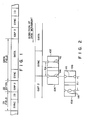
- FIG. 1 illustrates the format of each track; each sector has an identification (ID) field and a data field.
- ID field is separated from the data field by GAP2 field in which 22 bytes of data (4E) H are written.
- the ID field includes a SYNC subfield in which data (00) H is written and an ID subfield in which an identification code is written.
- the data field includes a SYNC subfield in which data (00) H is written and a data subfield in which recording data is written.
- the adjacent sectors are separated from each other by GAP3 field.
- the conventional floppy disk drive is provided with a tunnel erase head or a straddle head.
- the head records data on each track, and, at the same time, erases the recorded data from either side of the target track by a predetermine width.
- the typical straddle head comprises a read/write (R/W) core having a R/W gap and erase cores each located on either side of the R/W gap, having an erase gap being provided between the R/W core and erase core.
- R/W read/write
- erase cores each located on either side of the R/W gap, having an erase gap being provided between the R/W core and erase core.
- a data signal is supplied to a R/W coil wound around the R/W core for data writing
- an erase signal is supplied to an erase coil wound around each erase core to, thereby erase the data signals recorded on both side portions of the target track by a predetermined width.
- the output of the straddle head has a low S/N ratio. Because of the low S/N ratio, the straddle head is not usually in a floppy disk drive; rather, the tunnel erase head type drive is typically used in the conventional floppy disk drive.
- a tunnel erase head comprises R/W head 106 having a R/W core having a R/W gap 116 and a coil wound around the core, and an erase head 108 disposed backward regarding to R/W head 106.
- Erase head 108 has two gaps 118 aligned with the ends of R/W gap 116.
- a data signal is supplied to the R/W coil wound round the R/W core, while an erase signal is supplied to the erase coil wound around the erase core. Therefore, following the recording of data signals on the recording medium, the data signals recorded on both side portions of the target track are erased.
- erase gaps 118 is located backword regording to R/W gap 116 by distance X T .
- the supply of the erase signal to the erase coil must be delayed by time ⁇ T TON from the start of the data recording and stopping the supply of the erase signal must be delayed by time ⁇ T TOFF from the end of the recording thereof.
- a host computer supplies the floppy disk controller (FDC) with a timing signal representing the record-starting time and the record-ending time.
- the timing signal is supplied to a control circuit provided within the FDC.
- the control circuit outputs write gate signal WG and erase gate signal EG to the FDD.
- signal WG will be used to supply a write data signal WD to the R/W coil.
- Signal EG is delayed by time ⁇ T T from the signal WG.
- the recording medium is rotated at a constant speed, and hence, linear velocity V T of the recording medium relating to the magnetic head varies depending on the tracks. Therefore, it is desired that time ⁇ T T be changed whenever the head moves from one track to another.
- time ⁇ T TON is determined such that the tunnel erase head can entirely erase the data recorded on the track on both sides from a start position where recording of the data is started even when the head is positioned at the outermost track where linear velocity V T is the maximum.
- the time ⁇ T TOFF is determined such that the tunnel erase head can assuredly erase the data recorded on the track on both sides to a end position where recording of the data is ended even when the head is positioned at the innermost track of the recording medium where the linear velocity V T is the minimum.
- Gap regions are provided for protecting the data against a fluctuation of the data field, which may happen due to a dimensional error of the floppy disk drive or change in rotational speed of the recording medium.
- Hexadecimal data FF in FM recording or data 4e in MFM recording is written in these gap field. Since the over-erased areas produced preceding and following the data field fall within these gap fields, there will be no problems.
- a floppy disk drive should record data on a recording medium in a high density.
- a perpendicular recording floppy disk has been developed, which comprises barium ferrite layer, as a magnetic material, coated on a base film, and has a 4MB receding capacity.
- the width of the read gap must have a narrower. In most floppy disk drives, the read gap is used also as the write gap so that the write gap inevitably becomes narrower.
- the depth of the magnetization region can be magnetized is said to be about the same as the length of the write gap. Therefore, in order to erase signals completely from a track by overwriting new data on the same track, it is required that the thickness of the magnetic layer be about a quarter of the wavelength of a data signal. This is explained in "The Reproduction Of Magnetically Recorded Signals" written by Wallace, Jr, Bell System Technology Journal, Vol. 30, No. 4, 1951. For instance, with the recording density, of 35 KBPI, the read/write gap length must be set at about 0.5 um in consideration of gap loss, and thus the magnetic layer must have a thickness of about 0.5 um or less.
- the preerase head comprises a R/W Read 104 having a R/W gap 114 and a preerase head 102 provided upstream of the R/W head 104 with respect to the direction of movement of a recording medium.
- Preerase head 102 has an erase gap 112, which faces read/write gap 114 and is longer and wider than R/W gap 114.
- data signals are recorded on the target track in the following manner.
- an erase signal is supplied to an erase coil wound around an erase core, and the track area is widely erased to the deep area of the magnetic layer of the recording medium by erase gap 112 reaching the recording position on the recording medium, preceding R/W gap 114.
- new data are recorded in the data field from which the previously-recorded data have been completely erased, by R/W gap 114 which reaches this data field following the erase gap 112. Even with a disk having a high recording density in use, therefore, the overwrite characteristic is not be deteriorated.
- a write gate signal (WG), an erase gate signal (EG) and a write data signal (WD) are sent to the preerase head type FDD from a FDC.
- WG write gate signal
- EG erase gate signal
- WD write data signal
- phase relationship between the write gate signal and the erase gate signal in the preerase type FDD is opposite to the phase relationship involved in the tunnel erase type FDD.
- the erase gate signal cannot be produced from the write gate signal in the preerase type FDD.
- the SYNC subfield since the content of the SYNC subfield is used as a sync signal in data reproduction, if the SYNC subfield has a deteriorated overwrite characteristic due to having the unerased area, the S/N ratio of a reproduction signal from the unerased area in the data reproduction as well as the tracking characteristic of a PLL circuit on the basis of the reproduction signal from the magnetic head are deteriorated.
- the apparatus comprises: a first floppy disk drive (FDD) of a preerase head type including a first read/write section responsive to an incoming write gate (WG) signal and an incoming first selection signal for selectively recording on a disk first recorded data corresponding to a write data (WD) signal input thereto, for selectively reading the first recorded data from the disk to generate a first read data (RD) signal corresponding to the first recorded data as a RD signal; and a second FDD of a tunnel erase head type including a second read/write section responsive to the write gate (WG) signal input thereto and a second selection signal input thereto for selectively recording on a disk, second recorded data corresponding to an incoming WD signal, for selectively reading the second recorded data from the disk to generate a second RD signal corresponding to the read recorded data as a RD signal.
- FDD floppy disk drive
- WG incoming write gate
- WD write data
- a write gate signal generating section selectively generates a first WG signal for the first FDD and a second WG signal for the second FDD in response to sync signal input thereto to selectively output one of the first and second WG signals to the first and second FDDs as the WG signal in accordance with a mode signal input thereto.
- Selection signal generating section selectively outputs the first and second selection signals to the first and second FDDS, respectively, in response to a selection signal generated in accordance with a write command.
- a sync signal generating section generates a sync signal from the RD signal from one of the first and second FDDS, and a mode signal supplying section generates a mode signal in accordance with the write command and outputs it to the write gate signal generating section.
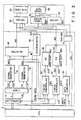
- a magnetic recording/reproduction apparatus for example, a magnetic recording/reproduction apparatus comprises CPU 2, floppy disk controller (FDC) 4, and floppy disk drive 50 or 52.
- CPU 2 controls the operation of FDC 4 and outputs a mode signal M, and a drive select signal SEL in accordance with a write command to be executed and write data to FDC 4 in accordance with read data output from FDC 4.
- FDC 4 has controller 11 for generating signal S in accordance with a read data controller 11 outputs the read data to CPU 2 and inputs write data from CPU 2.
- Timer 12 generates trigger pulses TR1 and TR2 in accordance with signal S from controller 11 and clock CLK.
- Pulse TR2 is generated when a floppy disk rotates by an amount corresponding to 22 bytes after signal S is input from controller 11, while pulse TR1 is generated when the disk rotates by an amount corresponding to 3 bytes.
- Signal generators 14 and 16 respectively generate write gate signals WG2 and WG1 in accordance with trigger pulses TR2 and TR1 from timer 12 and send the write gate signals to selector 18.
- Selector 18 selectively outputs one of received signals WGl and WG2 as a write gate signal WG to FDD 50/52 in accordance with signal M from CPU 2.
- Timing controller 20 generates data output instruction signal OI1 in accordance with signal WG1, signal M, and clock CLK. Controller 20 is preset with a time value corresponding to 19 bytes for 1/2 M bytes mode and 38 bytes for 4 M bytes mode, and the tie value is decremented each time signal OI1 is generated. When signal WG1 is selected by selector 18 responding to signal M, controller 20 generates signal OI1 in response to clock CLK if the decremented time value is not "0.”
- Data shift register 26 is preset in advance with data "4E” H and outputs the data "4E” bit by bit as write data signal WD to FDD 50/52 in accordance with signal OI1 from controller 20. After outputting signal OI1 to shift register 26 so that the register 26 outputs 19 bytes of write data in succession, controller 20 outputs an output enable signal OE1 to timing controller 22 and is then reset.
- Timing controller 22 generates data output instruction signal OI2 in accordance with signal M, signal WG2, clock CLK, and output enable signal OE1.
- selector 18 selects signal WG2 in response to signal M
- controller 22 is controlled by the signal WG2.
- controller 22 is controlled by signal OE1.
- This controller 22 is preset with a time value corresponding to 12 byte, generates signal OI2 upon reception of each clock CLK, and the time value is decremented in response to each clock CLK.
- Data shift register 28 is preset in advance with data "00" H , and sends the data "00" bit by bit as write data signal WD to FDD 50/52 in accordance with signal OI2 from controller 22. After outputting signal OI2 to cause shift register 28 to output 12 byte of write data, controller 22 sends output enable signal OE2 to data converter 24 and is then reset. Data converter 24 outputs the write data from CPU 2 bit by bit, as signal WD, to FDD 50/52 in accordance with clock CLK and output enable signal OE2 output from controller 22.
- Decoder 19 decodes signal SEL from CPU 2 and generates signal DS1 or DS2 to designate either FDD 50 or 52 to be accessed.
- Discriminator 30 produces read data from read data signal RD output from FDD 50 or 52 and sends signal RD to controller 11.
- Fig. 3 illustrates two FDDS, namely, preerase head type FDD 50 and tunnel erase head type FDD 52 for diagrammatical simplicity.
- the tunnel erase head type FDD 52 comprises driver 32, read/write (R/W) head 34, timer/driver 36 and erase head 38
- the preerase head type FDD 50 comprises driver 32, R/W head 34, a driver 40 and erase head 38.
- driver 32 In preerase head type FDD 50, driver 32 outputs signal WD to head 34 in accordance with signal WG upon reception of signal DS1 to cause the head to write data on the disk.
- timer/driver 36 is also supplied with signal DS2 and signal WG, and generates erase signal E having a phase delay of ⁇ T T from signal WG and outputs it to head 38.
- FDDs currently coupled to CPU 2 are registered in CPU 2. With reference to one of such FDDs at a time, the execution of a write command by CPU 2 for write access will now be explained.
- step S2 of Fig. 10 mode signal M is supplied to selector 18 and controller 22 and signal SEL is supplied to decoder 19 is step S4. Decoder 19 generates signal DS1 and sends it to FDD 50, rendering FDD 50 to be accessible. Then, head 34 reads out data from the ID subfield as shown in Fig. 1 and sends the readout data to controller 11 through discriminator 30 in step S6. When controller 11 acknowledges the reading of the data from the ID subfield, it outputs signal S to timer 12 in step S8.
- timer 12 In response to signal S, timer 12 counts clock CLK and sends trigger pulse TR1 to signal generator 16 after counting the clocks for 3 bytes.
- generator 16 In response to pulse TR1, generator 16 generates write gate signal WG1 and sends it to selector 18 and controller 20.
- Selector 18 selects signal WG1 in accordance with signal M and sends it to FDD 50 as signal WG at timing E as shown in Fig. 5A.
- gap 60 of R/W head 34 is positioned at the beginning of the SYNC subfield of the data field as shown in Fig. 6A, while gap 62 of erase head 38 is positioned upstream of the beginning of the SYNC subfield.
- driver 40 In FDD 50, driver 40 generates erase signal E in accordance with signal WG at the same timing as the signal WG, as shown in Fig. 5B, so that already-recorded data is erased from the SYNC subfield.
- controller 20 upon reception of signal WG1, controller 20 sends signal OI1 to register 26 in response to clock CLK.
- Register 26 sequentially outputs bit data corresponding to "4E" H as signal WD to FDD 50 at the timing E as shown in Fig. 5C, in response to signal OI1.
- write data is written on the disk through driver 32 and head 34. That is, since gap 62 of erase head 38 lies on GAP2 field at the timing when signal WG becomes active, GAP data needs to be written.
- controller 20 sends signal OE1 to controller 22.
- timer 12 outputs trigger pulse TR2 to generator 14 when counting the clocks for 22 bytes.
- generator 14 In response to pulse TR2, generator 14 generates write gate signal WG2 and sends it to selector 18. However, selector 18 does not select signal WG2.
- controller 22 When signal WG1 is selected in accordance with signal M, controller 22 outputs signal OI2 to register 28 in response to clock CLK upon reception of signal OE1. Register 28 sequentially outputs bit data corresponding to "00" H as signal WD to FDD 50 in response to signal OI2, as shown in Fig. 5C. Consequently, write data is written on the disk as data of the SYNC subfield through driver 32 and head 34.
- controller 22 sends signal OE2 to converter 24.
- converter 24 Upon reception of this signal OE2, converter 24 outputs the write data from CPU 2 via controller 11 as bit data signal WD to FDD 50 in response to clock CLK. Consequently, the write data is written on the disk as data of the data subfield through driver 32 and head 34.
- timer 12 In response to signal S, timer 12 counts clock CLK and sends trigger pulse TR1 to signal generator 16 after counting the clocks for 3 bytes.
- generator 16 In response to pulse TR1, generator 16 generates write gate signal WG1 and sends it to selector 18 and controller 20.
- selector 18 does not select signal WG1 in accordance with signal M, nor does controller 20 generate signal OI1 in accordance with signal M even upon reception of signal WG1.
- timer 12 After counting the clocks for 22 bytes, timer 12 sends trigger pulse TR2 to generator 14. In response to pulse TR2, generator 14 generates write gate signal WG2 and sends it to selector 18. Selector 18 selects signal WG2 in accordance with signal M and sends it to FDD 52 as signal WG at timing A as shown in Fig. 4A. At this time, gap 64 of R/W head 34 is positioned at the beginning of the SYNC subfield of the data field as shown in Fig. 7A, while gaps 66 of erase head 38 are positioned in GAP2 field. In FDD 52, timer/driver 36 generates erase signal E in accordance with signal WG with a time delay of ⁇ T T from signal WG as shown in Fig. 4B, so that currently-recorded data is erased at the both sides from the SYNC subfield of the disk.
- controller 22 outputs signal OI2 to register 28 in response to clock CLK upon reception of signal WG2.
- Register 28 sequentially outputs bit data corresponding to "00" H as signal WD to FDD 52 in response to signal OI2 at timing A, as shown in Fig. 4C. Consequently, write data is written on the disk through driver 32 and head 34. That is, gap 64 of R/W head 34 starts writing data in the data field at timing A when signal WG becomes active.
- controller 22 sends signal OE2 to converter 24.
- converter 24 Upon reception of this signal OE2, converter 24 outputs the write data from CPU 2 via controller 11 as bit data signal WD to FDD 52 in response to clock CLK. Consequently, the write data is written on the disk as data of the data subfield through driver 32 and head 34.
- signals M and SEL is directly output from CPU 2 to selector 18 and decoder 19, respectively. However, these signals may be output via controller 11.
- timer 12 receives signal S from controller 11 via discriminator 30 and selector 18 receives one of mode signals M1 or M2 from FDDS 50 ⁇ or 52 as signal M.
- Timing controller 20 ⁇ does not receive signal M and generates data output instruction signal OI1 in accordance with signal WG1 and clock CLK.
- Data shift register 26 ⁇ is supplied with signal M from mode setter 42, which signal is used to determine whether or not shift register 26 ⁇ should output data "4E" bit by bit as write data signal WD in accordance with signal OI1.
- Timing controller 22 ⁇ does not also receive signal M, and therefore generates signal OI2 in accordance with signal OE1 sent from controller 20 ⁇ .
- Discriminator 30 produces read data from a read data signal read by head 34 and sends the data to controller 11. When controller 11 detects the end of data of the ID subfield, it outputs signal S to timer 12.
- timer/driver 40 ⁇ is used for driver 40.
- Driver 40 ⁇ generates signal E as shown in Fig. 5D in accordance with signal WG; signal E becomes inactive ⁇ T T earlier than signal WG.
- Each FDD 50 ⁇ or 52 has mode setter 42, which is set in advance depending on the type of a FDD to be used and outputs signals M1 and M2 to FDC 4 in accordance with signals DS1 and DS2.
- preerase head type FDD 50 ⁇ When CPU 2 executes a write command, signal SEL is output to decoder 19 and selector 25. As a result, signal M1 from FDD 50 ⁇ is selected and sent as signal M to selector 18 and register 26 ⁇ . Then, head 34 reads data from the ID field as shown in Fig. 1, and controller 11 outputs signal S to timer 12 when it discriminates that the data of the ID subfield has been read.
- register 26 ⁇ Upon reception of signal OI1 generated from controller 20 ⁇ in accordance with signal WG1, register 26 ⁇ outputs bit data of "4E" H as signal WD in response to clock CLK because FDD 50 ⁇ is selected.
- the subsequent operation is the same as is done in the first embodiment.
- signal E becomes active in accordance with signal WG at the same time as the signal WG, the signal E is rendered inactive by a timer provided in timer/driver 40 ⁇ prior to time ⁇ Tp at which signal WG becomes inactive. Accordingly, it is the entire data field which is to be erased by erase gap 60, leaving GAP3 field unerased. This completes the write operation for one sector with respect to preerase head type FDD 50 ⁇ .
- controller 20 ⁇ When timer 12 counts the clocks for 3 bytes, controller 20 ⁇ generates signal OIl in response to signal WG2 from generator 16. Since signal WG1 has been selected by signal M, however, register 26 ⁇ does not output data "4E" as signal WD.
- controller 20 ⁇ sends signal OE1 to controller 22 ⁇ . Controller 22 ⁇ generates signal OI2 in accordance with signal WG2 and sends it to register 28. The subsequent operation is the same as is done in the first embodiment. In this manner, the write operation for one sector with respect to tunnel erase head type FDD 52 is completed.
Landscapes
- Engineering & Computer Science (AREA)
- Theoretical Computer Science (AREA)
- Human Computer Interaction (AREA)
- Physics & Mathematics (AREA)
- General Engineering & Computer Science (AREA)
- General Physics & Mathematics (AREA)
- Digital Magnetic Recording (AREA)
- Signal Processing For Digital Recording And Reproducing (AREA)
Applications Claiming Priority (2)
| Application Number | Priority Date | Filing Date | Title |
|---|---|---|---|
| JP44523/87 | 1987-02-27 | ||
| JP4452387 | 1987-02-27 |
Publications (3)
| Publication Number | Publication Date |
|---|---|
| EP0280326A2 true EP0280326A2 (de) | 1988-08-31 |
| EP0280326A3 EP0280326A3 (en) | 1990-03-21 |
| EP0280326B1 EP0280326B1 (de) | 1994-01-12 |
Family
ID=12693883
Family Applications (1)
| Application Number | Title | Priority Date | Filing Date |
|---|---|---|---|
| EP88102915A Expired - Lifetime EP0280326B1 (de) | 1987-02-27 | 1988-02-26 | System und Verfahren zur mehrfachen Ausnutzung eines Floppy-disk Kontrollers für verschiedene Floppy-disk geräte |
Country Status (4)
| Country | Link |
|---|---|
| US (1) | US4916557A (de) |
| EP (1) | EP0280326B1 (de) |
| KR (1) | KR910002760B1 (de) |
| DE (1) | DE3886961T2 (de) |
Cited By (2)
| Publication number | Priority date | Publication date | Assignee | Title |
|---|---|---|---|---|
| DE3842079A1 (de) * | 1988-12-14 | 1990-06-21 | Broadcast Television Syst | Verfahren zum aufzeichnen von signalen und magnetkopfanordnung hierfuer |
| EP0522483A3 (en) * | 1991-07-09 | 1993-12-22 | Fujitsu Ltd | Computer apparatus and storage device having controlled power saving apparatus |
Families Citing this family (5)
| Publication number | Priority date | Publication date | Assignee | Title |
|---|---|---|---|---|
| US5440693A (en) * | 1990-07-19 | 1995-08-08 | International Business Machines Corp. | Personal computer with drive identification |
| US5142626A (en) * | 1990-07-20 | 1992-08-25 | International Business Machines Corp. | Personal computer with removable media identification |
| JP3042790B2 (ja) * | 1991-01-23 | 2000-05-22 | 株式会社日立製作所 | 磁気ディスク装置及びそのデータ書き込み/読み出し制御方法 |
| US5784216A (en) * | 1995-11-16 | 1998-07-21 | Seagate Technology, Inc. | Method and apparatus for recording defective track identification information in a disk drive |
| US7477524B2 (en) | 2005-03-02 | 2009-01-13 | Woodward Governor Company | Retainer and method for holding a circuit card against a clamping surface of a chassis or heatsink |
Family Cites Families (11)
| Publication number | Priority date | Publication date | Assignee | Title |
|---|---|---|---|---|
| US4122306A (en) * | 1975-11-24 | 1978-10-24 | Jacob Friedman | Telephone answering apparatus providing selective message communication |
| DE2708760C3 (de) * | 1977-03-01 | 1980-08-14 | Licentia Patent-Verwaltungs-Gmbh, 6000 Frankfurt | Schaltungsanordnung mit mehreren unterschiedlichen Daten-Umlauf speichern und einem Zugriffssteuerwerk |
| US4357635A (en) * | 1979-03-20 | 1982-11-02 | Ricoh Company, Ltd. | Disc memory apparatus |
| US4357657A (en) * | 1979-08-24 | 1982-11-02 | Monolithic Systems, Corp. | Floppy-disk interface controller |
| US4300174A (en) * | 1979-12-21 | 1981-11-10 | Persci, Inc. | Guard band control for magnetic disks |
| JPS5782242A (en) * | 1980-11-12 | 1982-05-22 | Aiwa Co Ltd | Video recorder and reproducer |
| JPS59185069A (ja) * | 1983-04-04 | 1984-10-20 | Mitsubishi Electric Corp | 記録媒体読み出し制御システム |
| JPS59207068A (ja) * | 1983-05-10 | 1984-11-24 | Panafacom Ltd | フロツピイデイスク装置 |
| US4612613A (en) * | 1983-05-16 | 1986-09-16 | Data General Corporation | Digital data bus system for connecting a controller and disk drives |
| JPH0610845B2 (ja) * | 1984-02-18 | 1994-02-09 | ティアツク株式会社 | デジタル磁気記録再生装置 |
| JPS60205859A (ja) * | 1984-03-30 | 1985-10-17 | Sharp Corp | フロツピ−デイスクドライブ制御装置 |
-
1988
- 1988-02-25 US US07/160,409 patent/US4916557A/en not_active Expired - Fee Related
- 1988-02-26 EP EP88102915A patent/EP0280326B1/de not_active Expired - Lifetime
- 1988-02-26 DE DE88102915T patent/DE3886961T2/de not_active Expired - Fee Related
- 1988-02-27 KR KR8802053A patent/KR910002760B1/ko not_active Expired
Cited By (3)
| Publication number | Priority date | Publication date | Assignee | Title |
|---|---|---|---|---|
| DE3842079A1 (de) * | 1988-12-14 | 1990-06-21 | Broadcast Television Syst | Verfahren zum aufzeichnen von signalen und magnetkopfanordnung hierfuer |
| EP0522483A3 (en) * | 1991-07-09 | 1993-12-22 | Fujitsu Ltd | Computer apparatus and storage device having controlled power saving apparatus |
| US5652891A (en) * | 1991-07-09 | 1997-07-29 | Fujitsu Limited | Computer apparatus and external storage device which can be used by external power and internal power source |
Also Published As
| Publication number | Publication date |
|---|---|
| US4916557A (en) | 1990-04-10 |
| KR880010415A (ko) | 1988-10-08 |
| DE3886961T2 (de) | 1994-04-28 |
| EP0280326A3 (en) | 1990-03-21 |
| KR910002760B1 (en) | 1991-05-04 |
| EP0280326B1 (de) | 1994-01-12 |
| DE3886961D1 (de) | 1994-02-24 |
Similar Documents
| Publication | Publication Date | Title |
|---|---|---|
| EP0516125B1 (de) | Plattengerät | |
| US5617264A (en) | Method and apparatus for rewriting data to a floppy disk by storing reproduced data in a memory | |
| US6115199A (en) | Circuit for preventing servo sector from being overwritten due to misdetection of a servo address mark in a magnetic disk | |
| KR100464433B1 (ko) | 헤드의 열 운동과 인접 트랙 잠식 효과를 구분하기 위한방법 및 장치 | |
| GB2321760A (en) | Stable unlatch control of magnetic storage devices | |
| JPS619806A (ja) | 磁気デイスク記録装置 | |
| US4916557A (en) | Method of sharing various types of medium drives and recording/reproduction apparatus with medium controller for realizing the method | |
| EP0996115A3 (de) | Servosystem und Verfahren mit digitalgesteuertem Oszillator | |
| US4901169A (en) | Data recording apparatus able to accurately access a floppy disk regardless of recording density | |
| US5038230A (en) | Method of accurately executing read access and magnetic recording/reproducing apparatus therefor | |
| US5790333A (en) | Disk drive having optimized off-track compensation | |
| KR19990010651A (ko) | 자기 디스크 드라이브에서의 헤드 언래치 제어방법 | |
| US4779146A (en) | Apparatus for and method of writing/reading data into/from a flexible disk | |
| US6128154A (en) | Servo control method for a high capacity hard disk drive | |
| EP0285452A2 (de) | Magnetplattengerät mit sowohl Servofläche-Servo als auch Datenfläche-Servo | |
| US4466025A (en) | Floppy disc device with a delay mechanism | |
| JP2597627B2 (ja) | 磁気記録再生装置及び同装置に適用するデータ記録制御装置 | |
| KR910002617B1 (ko) | 자기디스크 구동시스템 및 이 자기디스크 구동시스템을 이용한 데이타 처리 장치 | |
| US6031674A (en) | Servo pattern forming method for floppy disk | |
| JPH0612562B2 (ja) | 磁気記録再生装置 | |
| JPS60224149A (ja) | 磁気記録再生装置 | |
| JPS6353607B2 (de) | ||
| JPS6052973A (ja) | 磁気記録再生装置 | |
| JPH011104A (ja) | 磁気記録再生装置及び同装置に適用するデータ記録制御装置 | |
| JP2624705B2 (ja) | 磁気ディスク装置 |
Legal Events
| Date | Code | Title | Description |
|---|---|---|---|
| PUAI | Public reference made under article 153(3) epc to a published international application that has entered the european phase |
Free format text: ORIGINAL CODE: 0009012 |
|
| 17P | Request for examination filed |
Effective date: 19880323 |
|
| AK | Designated contracting states |
Kind code of ref document: A2 Designated state(s): DE FR GB IT NL |
|
| PUAL | Search report despatched |
Free format text: ORIGINAL CODE: 0009013 |
|
| AK | Designated contracting states |
Kind code of ref document: A3 Designated state(s): DE FR GB IT NL |
|
| 17Q | First examination report despatched |
Effective date: 19911001 |
|
| GRAA | (expected) grant |
Free format text: ORIGINAL CODE: 0009210 |
|
| AK | Designated contracting states |
Kind code of ref document: B1 Designated state(s): DE FR GB IT NL |
|
| PG25 | Lapsed in a contracting state [announced via postgrant information from national office to epo] |
Ref country code: IT Free format text: LAPSE BECAUSE OF FAILURE TO SUBMIT A TRANSLATION OF THE DESCRIPTION OR TO PAY THE FEE WITHIN THE PRE;WARNING: LAPSES OF ITALIAN PATENTS WITH EFFECTIVE DATE BEFORE 2007 MAY HAVE OCCURRED AT ANY TIME BEFORE 2007. THE CORRECT EFFECTIVE DATE MAY BE DIFFERENT FROM THE ONE RECORDED.SCRIBED TIME-LIMIT Effective date: 19940112 |
|
| REF | Corresponds to: |
Ref document number: 3886961 Country of ref document: DE Date of ref document: 19940224 |
|
| ET | Fr: translation filed | ||
| PLBE | No opposition filed within time limit |
Free format text: ORIGINAL CODE: 0009261 |
|
| STAA | Information on the status of an ep patent application or granted ep patent |
Free format text: STATUS: NO OPPOSITION FILED WITHIN TIME LIMIT |
|
| 26N | No opposition filed | ||
| PGFP | Annual fee paid to national office [announced via postgrant information from national office to epo] |
Ref country code: FR Payment date: 20010213 Year of fee payment: 14 |
|
| PGFP | Annual fee paid to national office [announced via postgrant information from national office to epo] |
Ref country code: GB Payment date: 20010221 Year of fee payment: 14 Ref country code: DE Payment date: 20010221 Year of fee payment: 14 |
|
| PGFP | Annual fee paid to national office [announced via postgrant information from national office to epo] |
Ref country code: NL Payment date: 20010228 Year of fee payment: 14 |
|
| REG | Reference to a national code |
Ref country code: GB Ref legal event code: IF02 |
|
| PG25 | Lapsed in a contracting state [announced via postgrant information from national office to epo] |
Ref country code: GB Free format text: LAPSE BECAUSE OF NON-PAYMENT OF DUE FEES Effective date: 20020226 |
|
| PG25 | Lapsed in a contracting state [announced via postgrant information from national office to epo] |
Ref country code: NL Free format text: LAPSE BECAUSE OF NON-PAYMENT OF DUE FEES Effective date: 20020901 |
|
| PG25 | Lapsed in a contracting state [announced via postgrant information from national office to epo] |
Ref country code: DE Free format text: LAPSE BECAUSE OF NON-PAYMENT OF DUE FEES Effective date: 20020903 |
|
| GBPC | Gb: european patent ceased through non-payment of renewal fee |
Effective date: 20020226 |
|
| PG25 | Lapsed in a contracting state [announced via postgrant information from national office to epo] |
Ref country code: FR Free format text: LAPSE BECAUSE OF NON-PAYMENT OF DUE FEES Effective date: 20021031 |
|
| NLV4 | Nl: lapsed or anulled due to non-payment of the annual fee |
Effective date: 20020901 |
|
| REG | Reference to a national code |
Ref country code: FR Ref legal event code: ST |