EP0280237A2 - Wellenlängen-Multiplexer/-Demultiplexer für mehrere Kanäle - Google Patents
Wellenlängen-Multiplexer/-Demultiplexer für mehrere Kanäle Download PDFInfo
- Publication number
- EP0280237A2 EP0280237A2 EP88102575A EP88102575A EP0280237A2 EP 0280237 A2 EP0280237 A2 EP 0280237A2 EP 88102575 A EP88102575 A EP 88102575A EP 88102575 A EP88102575 A EP 88102575A EP 0280237 A2 EP0280237 A2 EP 0280237A2
- Authority
- EP
- European Patent Office
- Prior art keywords
- wavelengths
- beams
- polarized light
- parallel
- wavelength
- Prior art date
- Legal status (The legal status is an assumption and is not a legal conclusion. Google has not performed a legal analysis and makes no representation as to the accuracy of the status listed.)
- Withdrawn
Links
Images


Classifications
-
- G—PHYSICS
- G02—OPTICS
- G02B—OPTICAL ELEMENTS, SYSTEMS OR APPARATUS
- G02B6/00—Light guides; Structural details of arrangements comprising light guides and other optical elements, e.g. couplings
- G02B6/24—Coupling light guides
- G02B6/26—Optical coupling means
- G02B6/28—Optical coupling means having data bus means, i.e. plural waveguides interconnected and providing an inherently bidirectional system by mixing and splitting signals
- G02B6/293—Optical coupling means having data bus means, i.e. plural waveguides interconnected and providing an inherently bidirectional system by mixing and splitting signals with wavelength selective means
- G02B6/29302—Optical coupling means having data bus means, i.e. plural waveguides interconnected and providing an inherently bidirectional system by mixing and splitting signals with wavelength selective means based on birefringence or polarisation, e.g. wavelength dependent birefringence, polarisation interferometers
-
- G—PHYSICS
- G02—OPTICS
- G02B—OPTICAL ELEMENTS, SYSTEMS OR APPARATUS
- G02B6/00—Light guides; Structural details of arrangements comprising light guides and other optical elements, e.g. couplings
- G02B6/24—Coupling light guides
- G02B6/26—Optical coupling means
- G02B6/28—Optical coupling means having data bus means, i.e. plural waveguides interconnected and providing an inherently bidirectional system by mixing and splitting signals
- G02B6/293—Optical coupling means having data bus means, i.e. plural waveguides interconnected and providing an inherently bidirectional system by mixing and splitting signals with wavelength selective means
- G02B6/29379—Optical coupling means having data bus means, i.e. plural waveguides interconnected and providing an inherently bidirectional system by mixing and splitting signals with wavelength selective means characterised by the function or use of the complete device
- G02B6/2938—Optical coupling means having data bus means, i.e. plural waveguides interconnected and providing an inherently bidirectional system by mixing and splitting signals with wavelength selective means characterised by the function or use of the complete device for multiplexing or demultiplexing, i.e. combining or separating wavelengths, e.g. 1xN, NxM
-
- G—PHYSICS
- G02—OPTICS
- G02B—OPTICAL ELEMENTS, SYSTEMS OR APPARATUS
- G02B6/00—Light guides; Structural details of arrangements comprising light guides and other optical elements, e.g. couplings
- G02B6/24—Coupling light guides
- G02B6/26—Optical coupling means
- G02B6/27—Optical coupling means with polarisation selective and adjusting means
- G02B6/2706—Optical coupling means with polarisation selective and adjusting means as bulk elements, i.e. free space arrangements external to a light guide, e.g. polarising beam splitters
- G02B6/2713—Optical coupling means with polarisation selective and adjusting means as bulk elements, i.e. free space arrangements external to a light guide, e.g. polarising beam splitters cascade of polarisation selective or adjusting operations
- G02B6/272—Optical coupling means with polarisation selective and adjusting means as bulk elements, i.e. free space arrangements external to a light guide, e.g. polarising beam splitters cascade of polarisation selective or adjusting operations comprising polarisation means for beam splitting and combining
-
- G—PHYSICS
- G02—OPTICS
- G02B—OPTICAL ELEMENTS, SYSTEMS OR APPARATUS
- G02B6/00—Light guides; Structural details of arrangements comprising light guides and other optical elements, e.g. couplings
- G02B6/24—Coupling light guides
- G02B6/26—Optical coupling means
- G02B6/27—Optical coupling means with polarisation selective and adjusting means
- G02B6/2753—Optical coupling means with polarisation selective and adjusting means characterised by their function or use, i.e. of the complete device
- G02B6/2766—Manipulating the plane of polarisation from one input polarisation to another output polarisation, e.g. polarisation rotators, linear to circular polarisation converters
-
- G—PHYSICS
- G02—OPTICS
- G02B—OPTICAL ELEMENTS, SYSTEMS OR APPARATUS
- G02B6/00—Light guides; Structural details of arrangements comprising light guides and other optical elements, e.g. couplings
- G02B6/24—Coupling light guides
- G02B6/26—Optical coupling means
- G02B6/27—Optical coupling means with polarisation selective and adjusting means
- G02B6/2753—Optical coupling means with polarisation selective and adjusting means characterised by their function or use, i.e. of the complete device
- G02B6/2773—Polarisation splitting or combining
Definitions
- This invention relates to a multiple channel (greater than two channels) birefringent multiplexer/demultiplexer. Accordingly, it is a general object of this invention to provide new and improved multiplexers and demultiplexers of such character.
- United States Patent Numbers 4,566,761 and 4,685,773 present the advantages of birefringent wavelength division multiplexing (WDM) over previously used methods of wavelength division multiplexing, including dichroic mirrors, gratings, and holographic gratings methods.
- WDM wavelength division multiplexing
- dichroic mirrors, gratings, and holographic gratings methods present the advantages of birefringent wavelength division multiplexing (WDM) over previously used methods of wavelength division multiplexing, including dichroic mirrors, gratings, and holographic gratings methods.
- the problems inherent in multiple channel multiplexing/demultiplexing with a nonbirefringent WDM were stated in the cited U.S. patent 4,566,761.
- the foregoing citations further describe a method of multiple channel multiplexing/demultiplexing with the birefringent WDM using a tree structure of filter stages.
- the four channel multiplexer/demultiplexer used three filter stages, A, B, C, where stage A had a channel separation of ⁇ and stages B and C had channel separations of 2 ⁇ .
- Successive branches would require that the stages in the parallel branch all be of different lengths to an accuracy of 2 ⁇ m. This stringent requirement would make for costly difficult production.
- Another object of this invention is to provide for a new and improved multiple channel wavelength division multiplexer/demultiplexer which simplifies the tolerances on the crystal lengths for successive filter stages where a filter stage is one complete two channel multiplexer.
- Still another object of this invention is to provide for a new and improved multiple channel wavelength division multiplexer/demultiplexer which avoids the use of a tree structure array by uniting the parallel branches of the tree structure into one filter stage, thereby reducing the number of stages from (n-1) to log2n where n is the number of channels being multiplexed or demultiplexed.
- each stage has a transfer function approximating a square wave and each successive stage has a halved period of the preceding stage.
- each successive stage has a period doubled that of the preceding stage.
- An input beam composed of n distinct wavelengths is demultiplexed into n output beams, each containing only one wavelength.
- Each stage consists of two polarizing beam splitters between which are located an appropriate number of birefringent crystal elements to achieve the desired transfer function.
- a multiple channel birefringent demultiplexing apparatus includes log2n stages, serially coupled together, where n represents a number of optical wavelengths capable of being demultiplexed, and log2n is an integer greater than 1.
- Each of the stages include an input polarizing beam splitting means, a length of birefringent material, and an output polarizing beam splitting means.
- the input polarizing beam splitting means converts an input beam of collimated light whose polarization state is immaterial into two orthogonally polarized output beams which are parallel to each other.
- the length of birefringent material has an input face and an output face, the faces being parallel for receiving the output beams normally applied to the input face.
- the material has a length and transfer function such that certain wavelengths pass therethrough with their polarization unchanged, and that remaining wavelengths have their polarization rotated by 90° at the output face.
- the output polarizing beam splitter means is coupled to the output face for receiving beams of polarized light therefrom and for converting same to collimated demultiplexed beams of light whose polarizations are immaterial.
- the input polarizing beam splitting means of the subsequent one of the stages is coupled to the output polarizing beamsplitter means of the immediately preceding one of the stages.
- n can be equal to 8
- log2n can be equal to 3.
- a collimated beam of light having wavelengths of ⁇ 1, ⁇ 2, ⁇ 3, ⁇ 4, ⁇ 5, ⁇ 6, ⁇ 7, ⁇ 8 can be applied to the input beam splitting means of a first of the stages.
- the wavelengths were adjacent to each other and are equally spaced with ⁇ 1 being lower than ⁇ 8 to produce at the input face of the birefringent material of the first stage one beam of parallel polarized light containing the wavelengths ⁇ 1, ⁇ 2, ⁇ 3, ⁇ 4, ⁇ 5, ⁇ 6, ⁇ 7, ⁇ 8 and one beam of perpendicular polarized light containing those wavelengths ⁇ 1, ⁇ 2, ⁇ 3, ⁇ 4, ⁇ 5, ⁇ 6, ⁇ 7, ⁇ 8.
- Both of the one beams are spaced apart and parallel to each other. They are applied to the input face of birefringent material of the first stage.
- the one beams traverse the length of the birefringent material of the first stage to yield a first pair of transferred beams.
- One of the transferred beams contains parallel polarized light at the wavelengths ⁇ 1, ⁇ 2, ⁇ 3, ⁇ 4 and perpendicular polarized light at the wavelengths ⁇ 5, ⁇ 6, ⁇ 7, ⁇ 8.
- the other of the transferred beams contain perpendicular polarized light at the wavelengths of ⁇ 1, ⁇ 2, ⁇ 3, ⁇ 4 and parallel polarized light at the wavelengths ⁇ 5, ⁇ 6, ⁇ 7, ⁇ 8, both of the first pair of transferred beams being applied to the output polarizing beam splitting means of the first stage whereby the output polarizing and beam splitting means of the first stage yields a first beam containing wavelengths ⁇ 5, ⁇ 6, ⁇ 7, ⁇ 8 and a second beam containing wavelengths ⁇ 1, ⁇ 2, ⁇ 3, ⁇ 4.
- the first beam and the second beam are directed to the input beam splitting means of a second of the stages to produce four parallel beams of polarized light at the input face of the birefringent material of the second stage.
- a first of the four parallel beams contain parallel polarized light having wavelengths at ⁇ 5, ⁇ 6, ⁇ 7, ⁇ 8, a second of the four parallel beams contain perpendicular polarized light having wavelengths at ⁇ 5, ⁇ 6, ⁇ 7, ⁇ 8, a third of the parallel beams contain parallel polarized light having wavelengths at ⁇ 1, ⁇ 2, ⁇ 3, ⁇ 4, and a fourth of said four parallel beams contain perpendicular polarized light having wavelengths at ⁇ 1, ⁇ 2, ⁇ 3, ⁇ 4, all of said four beams being spaced apart in multiple planes parallel to each other, being applied to the input face of the birefringent material of the second stage.
- the four parallel beams traverse the length of the birefringent material of the second stage to yield a quartet of transformed beams.
- One of the transformed beams contains parallel polarized light at wavelengths ⁇ 5, ⁇ 6, and perpendicular polarized light at wavelengths ⁇ 7, ⁇ 8.
- a second of the transformed beams contains perpendicular polarized light at wavelengths ⁇ 5, ⁇ 6 and parallel polarized light at wavelengths ⁇ 7, ⁇ 8.
- a third of the transformed beams contains parallel polarized light at wavelengths ⁇ 1, ⁇ 2 and perpendicular polarized light at wavelengths ⁇ 3, ⁇ 4.
- a fourth of the transformed beams contain perpendicular polarized light at wavelengths ⁇ 1, ⁇ 2, and parallel polarized light at wavelengths ⁇ 3, ⁇ 4. All four transformed beams are applied to the output polarized beam splitter means of the second stage.
- the output polarizing beam splitter means of the second stage yields a first intermediary beam containing wavelengths ⁇ 7, ⁇ 8.
- a second intermediary beam contains wavelengths ⁇ 5, ⁇ 6.
- a third intermediary beam contains wavelengths ⁇ 3, ⁇ 4.
- a fourth intermediary beam contains wavelengths of ⁇ 1, ⁇ 2.
- the four intermediary beams are directed to the input beam splitting means of a third of the stages to produce at the input face of the birefringent material of the third stage, eight parallel beams of polarized light.
- a first of the eight parallel beams contains parallel polarized light having wavelengths of ⁇ 7, ⁇ 8.
- a second of the eight parallel beams contains parallel polarized light having wavelengths of ⁇ 5, ⁇ 6.
- a third of the eight parallel beams contains parallel polarized light having wavelengths of ⁇ 3, ⁇ 4.
- a fourth of the eight parallel beams contains parallel polarized light having wavelengths of ⁇ 1, ⁇ 2.
- a fifth of the eight parallel beams contains perpendicular polarized light having wavelengths of ⁇ 7, ⁇ 8.
- a sixth of the eight parallel beams contains perpendicular polarized light having wavelengths of ⁇ 5, ⁇ 6.
- a seventh of the eight parallel beams contains perpendicular polarized light having wavelengths of ⁇ 3, ⁇ 4, and an eighth of the eight parallel beams contains perpendicular polarized light having wavelengths of ⁇ 1, ⁇ 2. All said eight parallel beams are spaced apart parallel to each other which are applied to the input face of the birefringent material of the third stage. The eight parallel beams travel the length of the birefringent material of the third stage to yield an octet of converted beams.
- One of the converted beams contains parallel polarized light of wavelength ⁇ 7, and perpendicular polarized light at wavelength ⁇ 8.
- a second of the converted beams contains parallel polarized light at wavelength ⁇ 5, and perpendicular light at wavelength ⁇ 6.
- a third of the converted beams contains parallel polarized light at wavelength ⁇ 3, and perpendicular polarized light at wavelength ⁇ 4.
- a fourth of the converted beams contains parallel polarized light at wavelength ⁇ 1, and perpendicular parallel light at wavelength ⁇ 2.
- a fifth of the converted beams contains perpendicular polarized light at wavelength ⁇ 7, and parallel polarized light at wavelength ⁇ 8.
- a sixth of the converted beams contains perpendicular polarized light at wavelength ⁇ 5, and parallel polarized light at wavelength ⁇ 6.
- a seventh of the converted beams contains perpendicular polarized light at wavelength ⁇ 3, and parallel polarized light at wavelength ⁇ 4.
- An eighth of the converted beams contains perpendicular polarized light at wavelength ⁇ 1, and parallel polarized light at wavelength ⁇ 2. All eight converted beams are applied to the output polarizing beam splitting means of the third stage whereby the output polarizing beam splitting means of the first stage yields a first demultiplexed beam at wavelength ⁇ 8, a second demultiplexed beam at wavelength ⁇ 6, a third demultiplexed beam at wavelength ⁇ 4, a fourth demultiplexed beam at wavelength ⁇ 2, a fifth demultiplexed beam at wavelength ⁇ 7, a sixth demultiplexed beam at wavelength ⁇ 5, a seventh demultiplexed beam at wavelength ⁇ 3, and an eighth demultiplexed beam at wavelength ⁇ 1.
- a multiple channel birefringent demultiplexing apparatus includes log2n stages serially coupled together, wherein n represents the number of optical wavelengths capable of being multiplexed and log2n is an integer greater than one.
- Each of the stages includes an input polarizing beam splitting means, a length of birefringent material, and an output polarizing beam splitting means.
- An input polarizing beam splitting means receives at least one input beam of collimated light whose polarization state is immaterial, and converts them into twice as many of orthogonally polarized output beams.
- the input and output beams are parallel to each other.
- the length of birefringent material has an input face and an output face.
- the faces are parallel for receiving output beams normally applied to the input face.
- the material has a length and transfer function such that certain wavelengths pass therethrough with their polarization unchanged and that remaining wavelengths have their polarization rotated by 90°.
- the output polarizing beam splitting means coupled to the output face receives 2 X beams of polarized light therefrom and converts same to 2 X collimated multiplexed beams of light whose polarization is immaterial, wherein X is a positive integer.
- the input polarizing beam splitting means of a subsequent one of the stages is coupled to the output polarizing beam splitter of the immediately preceding one of the stages.
- n is equal to 8
- log2n is equal to 3.
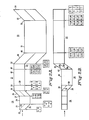
- the multichannel wavelength division multiplexer/demultiplexer as taught in this specification utilizes a polarizing beam splitter 11 having an input face 12 that is parallel with an output face 13.
- a first internal reflective surface 14 is likewise parallel to a second internal reflecting surface 16.
- a polarizing beam splitting element 17 is so oriented within the beam splitter 11 to be parallel with the reflecting surfaces 14, 16.
- Figs. 2A and 2B depict side and top view, respectively, of a three stage n-channel demultiplexer.
- An input collimated beam containing a plurality of wavelengths to be demultiplexed is depicted by the horizontal arrows shown at the left of the drawing, directed to the beam splitter 21 at its input face 22.
- the beam is directed to the beam splitter layer 23 causing parallel polarized light at the wavelengths supplied thereto, for example, wavelengths ⁇ 1, ⁇ 2, ⁇ 3, ⁇ 4, ⁇ 5, ⁇ 6, ⁇ 7, ⁇ 8 to pass directly therethrough to the first birefringent element 24.
- the beam splitting layer 23 reflects perpendicularly polarized light at the wavelengths ⁇ 1 through ⁇ 8 down to the internal reflecting surface 26 of the first polarizing beam splitter 21 causing the perpendicularly polarized beams of light at the wavelengths ⁇ 1,... ⁇ 8 to pass through the first birefringent element 24 at the lower portion of Fig. 2A.
- the upper beam of light through the first birefringent element 24 containing parallel polarized light at the wavelengths ⁇ 1 through ⁇ 8 is so transformed to provide a beam of light that contains parallel polarized light at the wavelengths ⁇ 1 through ⁇ 4 and perpendicular polarized light at wavelengths ⁇ 5 through ⁇ 8.
- the lower beam of light containing the perpendicular polarized beams at wavelengths ⁇ 1 through ⁇ 8 pass therethrough and are transformed to provide a beam containing perpendicular polarized light at the wavelengths ⁇ 1 through ⁇ 4 and parallel polarized light at wavelengths ⁇ 5 through ⁇ 8 as indicated at the interface 27 between the first birefringent element 24 and the output beam splitting means 28 of the first stage 29.
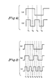
- waveform (a) illustrates the transform waveform for the various wavelengths ⁇ 1 through ⁇ 8. As indicated, the lower wavelengths ⁇ 1 through ⁇ 4 do not have their polarization changed, while the upper wavelength ⁇ 5 through ⁇ 8 do have their polarization changed.
- the beam containing the parallel polarized light at the wavelengths ⁇ 1 through ⁇ 4 and the perpendicular polarized light containing the wavelengths ⁇ 5 through ⁇ 8 together with the beam containing the perpendicular polarized light of wavelengths ⁇ 1 through ⁇ 4 and the parallel polarized light containing wavelengths ⁇ 5 through ⁇ 8 are both applied to the output beam splitter 28 of the first stage 29 whereby the two beams exit in a combined manner so that one beam emerges containing wavelengths ⁇ 5 through ⁇ 8 whose polarization state is immaterial and the other beam emerges containing wavelengths ⁇ 1 through ⁇ 4 whose polarization state is immaterial.
- a beam applied at its input facet 22 containing wavelengths ⁇ 1 through ⁇ 8 yields at its output interface 30 two beams, one beam containing wavelengths ⁇ 5 through ⁇ 8 and the other beam containing wavelengths ⁇ 1 through ⁇ 4.
- the second stage 31 has two beams applied thereto at the interface 30.
- One beam contains wavelengths ⁇ 5 through ⁇ 8 and the other beam contains wavelengths ⁇ 1 through ⁇ 4, yielding at its output interface 32 four sets of beams, one beam containing wavelengths ⁇ 7 and ⁇ 8, another beam containing wavelengths ⁇ 5 and ⁇ 6, a third beam containing wavelengths ⁇ 3 and ⁇ 4, and a fourth beam containing wavelengths ⁇ 1 and ⁇ 2.
- the third stage 33 having four beams of collimated light at immaterial polarization states, one beam containing wavelengths ⁇ 7, ⁇ 8, another beam at wavelengths ⁇ 5, ⁇ 6, a third beam at wavelengths ⁇ 3, ⁇ 4, and a fourth beam of wavelengths ⁇ 1, ⁇ 2, provides at its output facet 34 eight beams of light of different wavelengths, specifically wavelengths ⁇ 8, ⁇ 6, ⁇ 4, ⁇ 2, ⁇ 7, ⁇ 5, ⁇ 3, and ⁇ 1.
- the input beam applied to the facet 22 of the stage 29, containing light of no particular polarization at wavelengths ⁇ 1 through ⁇ 8, provides two output beams, one at wavelengths ⁇ 5 through ⁇ 8, and the other at wavelengths ⁇ 1 through ⁇ 4 at the interface 30.
- the input beam and the output beams are applied along a common plane.
- the two beams one carrying the wavelengths ⁇ 5 through ⁇ 8, and the other carrying the wavelengths ⁇ 1 through ⁇ 4, are applied to the second stage 31 to the interface 30 of an input beam splitter 36 of the second stage 31.
- the beam splitter 36 is rotated 90° with respect to the corresponding beam splitter 21 of the first stage 29 as will be more apparent from a view of the devices shown in Fig. 2B.
- the two beams (the upper beam containing the unpolarized light having wavelengths ⁇ 5 through ⁇ 8 and the lower beam containing unpolarized light containing wavelengths ⁇ 1 through ⁇ 4 ) are applied to the interface 30 of the input polarizing beam splitter 36 of the second stage 31.
- the light need not be unpolarized, the polarization state is immaterial.
- the aforesaid two beams are passed through the input polarization beam splitter 37 (Fig. 2B), some of the light passing directly through the beam splitting layer 37, while the remaining light is reflected by the beam splitter layer 37 to the internally reflected surface 38 of the beam splitter means 36, causing four beams to pass therethrough.
- the beam of light which contains the wavelengths ⁇ 5 through ⁇ 8 is transformed into two beams, one of which contains parallel polarized light at the wavelengths ⁇ 5 through ⁇ 8 and a second beam containing perpendicular polarized light at the wavelengths ⁇ 5 and ⁇ 8.
- the beam of unpolarized light at wavelengths ⁇ 1 through ⁇ 4 are converted into two other beams, one beam of which contains parallel polarized light at wavelengths ⁇ 1 through ⁇ 4 and the other beam containing perpendicular polarized light at wavelengths ⁇ 1 through ⁇ 4.
- the parallel polarized light at wavelengths ⁇ 5 through ⁇ 8 the perpendicular polarized light at wavelengths ⁇ 5 through ⁇ 8, the parallel polarized light at wavelengths ⁇ 1 through ⁇ 4, and the perpendicular polarized light at wavelengths ⁇ 1 through ⁇ 4 appear at the interface 39 of the input beam splitter 36 and a second birefringent element 41 of the second stage 31.
- Those four beams are: a parallel polarized beam of light at wavelengths ⁇ 5 through ⁇ 8, a perpendicular polarized beam of light at wavelengths ⁇ 5 through ⁇ 8, a parallel polarized beam of light at wavelengths ⁇ 1 through ⁇ 4, and a perpendicular polarized beam of light at wavelengths ⁇ 1 through ⁇ 4.
- the second birefringent element 41 has a transfer function as depicted at waveform (b) at Fig. 5 and has a length such that the output of the birefringent element 41 (at its interface 42 with its output beam splitter means 43) provides four transferred beams.
- One of the transferred beams contains parallel polarized light at wavelengths ⁇ 5 and ⁇ 6 and perpendicular polarized light at wavelengths ⁇ 7 and ⁇ 8.
- a second of the transferred beams contains perpendicular polarized light at wavelengths ⁇ 5 and ⁇ 6 and parallel polarized light at wavelengths ⁇ 7 and ⁇ 8,
- a third beam contains parallel polarized light at wavelengths ⁇ 1 and ⁇ 2 and perpendicular polarized light at wavelengths ⁇ 3 and ⁇ 4.
- a fourth beam of light contains perpendicular polarized light at wavelengths ⁇ 1 and ⁇ 2 and parallel polarized light at wavelengths ⁇ 3 and ⁇ 4, as viewed in Fig. 2A.
- the foregoing four beams of light at the interface 42 are directed to the output beam splitter 43 of the second stage 31.
- the internal reflecting surfaces 44, 46 and the beam splitter layers 47 (all of which are parallel to each other) so act upon the four beams having their designated wavelengths and polarization states to provide at the interface 32 (between the two stages 31 and 33) four beams of light whose polarization state is immaterial.
- One of those beams of light contains wavelengths at ⁇ 7 and ⁇ 8, a second beam containing light at wavelengths ⁇ 5 and ⁇ 6, a third beam containing light at wavelengths ⁇ 3 and ⁇ 4, and a fourth beam of light containing light at wavelengths ⁇ 1 and ⁇ 2.
- Those four beams of light at the interface 32 are directed to an input beam splitter means 48 of the third stage 33 at an angle preferably rotated 90° as indicated in Fig. 2.
- the rotation of 90° may be in the same or in the opposite direction as that between stages 1 and 2, it being immaterial whether a clockwise and a counter-clockwise direction is used. Further, it is deemed immaterial that the angle of rotation be precisely 90°. The specific angles are not deemed to be critical.
- the polarization beam splitter 48 splits those four beams to yield eight beams at the interface 49 (between the input beam splitter 48 and the third birefringent element 51 of the first stage 33).
- a second of those beams contains parallel polarized light at wavelengths ⁇ 5, ⁇ 6.
- a third beam contains parallel polarized light at wavelengths ⁇ 3, ⁇ 4.
- a fourth beam contains parallel polarized light at wavelengths ⁇ 1, ⁇ 2.
- a fifth beam contains perpendicular polarized light at wavelengths ⁇ 7, ⁇ 8.
- a sixth beam contains perpendicular polarized light at wavelengths ⁇ 5, ⁇ 6.
- a seventh beam contains perpendicular polarized light at wavelengths ⁇ 3, ⁇ 4.
- An eighth beam contains perpendicular polarized light at wavelengths ⁇ 1, ⁇ 2.
- the length of the third birefringent element 51 at the third stage 33 results in a transform waveform (as depicted in waveform (c) at Fig. 5), which transform those eight beams at the input interface 49 of the third birefringent element 51 into eight transformed beams at the interface 52 between the birefringent element 51 and the output beam splitter 53 of the third stage 33.
- Those transformed beams are such that the first beam contains parallel polarized light at wavelength ⁇ 7 and perpendicular polarized light at wavelength ⁇ 8.
- a second beam contains parallel polarized light at wavelength ⁇ 5 and perpendicular polarized light at wavelength ⁇ 6.
- a third beam contains parallel polarized light at wavelength ⁇ 3 and perpendicular polarized light at wavelength ⁇ 4.
- a fourth beam contains parallel polarized light at wavelength ⁇ 1 and perpendicular polarized light at wavelength ⁇ 2.
- a fifth beam contains perpendicular polarized light at wavelength ⁇ 7 and parallel polarized light at wavelength ⁇ 8.
- a sixth beam contains parallel polarized light at wavelength ⁇ 6 and perpendicular polarized light at wavelength ⁇ 5.
- a seventh beam contains perpendicular polarized light at wavelength ⁇ 3 and parallel polarized light at wavelength ⁇ 4.
- An eighth beam contains perpendicular polarized light at wavelength ⁇ 1 and parallel polarized light at wavelength ⁇ 2.
- the aforesaid latter eight beams of various wavelengths and polarizations at the interface 52 are applied to the output beam splitting means 53 of the third stage 33 so that at its output facet 34 eight beams of immaterial polarization are provided: namely, beams at wavelength ⁇ 8, a beam at wavelength ⁇ 6, a beam at wavelength ⁇ 4, a beam at wavelength ⁇ 2, a beam at wavelength ⁇ 7, a beam at wavelength ⁇ 5, a beam at wavelength ⁇ 3, and a beam at wavelength ⁇ 1.
- Fig. 3 depicts a perspective view somewhat based upon the views depicted in Figs. 2A and 2B, with the exception that different beam splitter means are illustrated.
- the specific type of beam splitting means is not critical due to the overall basic concept of this invention.
- Fig. 5 refers to a three stage system wherein the first birefringent stage has a transfer function as indicated in waveform (a) of Fig. 5, the second stage has a transfer function as indicated in waveform (b) of Fig. 5, while the third birefringent stage has the transfer function indicated in waveform (c) of Fig. 5.
- waveform (a) of Fig. 4 would indicate the transfer function of the first birefringent element while waveform (b) would indicate the transfer function for the second birefringent element.
- the second stage has birefringent crystal elements which are twice the length of the crystals in the first stage using a transfer function in phase with and having half the period of the transfer function of the first stage.
- the crystals in the second stage have increased lateral dimensions.
- the second stage is rotated, counter clockwise or clockwise (it does not matter), with respect to the first stage so that the parallel beams of the output port of the first stage enter the polarizing beam splitter of the second stage at different heights.
- n different wavelengths in one beam are inputted to the first stage with ⁇ 1 > ⁇ 2 > ⁇ 3...> ⁇ n, where n can be 4, 8, 16, ... 2 y where y is an integer, then ⁇ 1 ... ⁇ n/2 are in one output beam of stage one and ⁇ (n/2+1) ... ⁇ n are in the other output beam of stage one.
- n can be 4, 8, 16, ... 2 y where y is an integer
- ⁇ 1 ... ⁇ n/2 are in one output beam of stage one
- ⁇ (n/2+1) ... ⁇ n are in the other output beam of stage one.
- the third stage is rotated at 90° (clockwise or counter clockwise, it is immaterial) with respect to the second stage so that the four separate beams traveling in a parallel direction are all incident on the input polarizing beam splitter of the third stage.
- This pattern of individual filter stages of increasing dimension, each rotated by 90° from the previous filter stage continues through log2n filter stages when all n wavelengths are separated into n beams.
- the n-channel multiplexer is constructed in exactly the same manner except that the beams are propagated in the opposite direction.
Landscapes
- Physics & Mathematics (AREA)
- General Physics & Mathematics (AREA)
- Optics & Photonics (AREA)
- Optical Head (AREA)
- Optical Communication System (AREA)
Applications Claiming Priority (2)
| Application Number | Priority Date | Filing Date | Title |
|---|---|---|---|
| US18232 | 1987-02-24 | ||
| US07/018,232 US4745591A (en) | 1987-02-24 | 1987-02-24 | Multiple channel wavelength division multiplexer/demultiplexer |
Publications (2)
| Publication Number | Publication Date |
|---|---|
| EP0280237A2 true EP0280237A2 (de) | 1988-08-31 |
| EP0280237A3 EP0280237A3 (de) | 1990-07-04 |
Family
ID=21786898
Family Applications (1)
| Application Number | Title | Priority Date | Filing Date |
|---|---|---|---|
| EP88102575A Withdrawn EP0280237A3 (de) | 1987-02-24 | 1988-02-22 | Wellenlängen-Multiplexer/-Demultiplexer für mehrere Kanäle |
Country Status (4)
| Country | Link |
|---|---|
| US (1) | US4745591A (de) |
| EP (1) | EP0280237A3 (de) |
| JP (1) | JPS63296016A (de) |
| CA (1) | CA1275512C (de) |
Families Citing this family (19)
| Publication number | Priority date | Publication date | Assignee | Title |
|---|---|---|---|---|
| US4987567A (en) * | 1988-11-21 | 1991-01-22 | Gte Laboratories Incorporated | Optical wavelength multiplexer/demultiplexer and demultiplexer/remultiplexer |
| US5099114A (en) * | 1989-04-28 | 1992-03-24 | Nippon Telegraph & Telephone Corporation | Optical wavelength demultiplexer |
| CA2015211C (en) * | 1989-04-28 | 1993-10-05 | Takao Matsumoto | Optical wavelength demultiplexer |
| GB2245118A (en) * | 1990-06-14 | 1991-12-18 | Stc Plc | Optical wavelength division multiplexer/demultiplexer |
| EP0593205A1 (de) * | 1992-10-16 | 1994-04-20 | AT&T Corp. | Optischer Koppler |
| US5355237A (en) * | 1993-03-17 | 1994-10-11 | The United States Of America As Represented By The Administrator Of The National Aeronautics And Space Administration | Wavelength-division multiplexed optical integrated circuit with vertical diffraction grating |
| GB2286937B (en) * | 1994-02-26 | 1998-06-10 | Northern Telecom Ltd | Spectral polarisation separator |
| US5771120A (en) * | 1995-12-26 | 1998-06-23 | Lucent Technologies Inc. | Optical apparatus with combined polarization functions |
| US6163393A (en) | 1996-10-29 | 2000-12-19 | Chorum Technologies Inc. | Method and apparatus for wavelength multipexing/demultiplexing |
| US6847786B2 (en) | 1996-10-29 | 2005-01-25 | Ec-Optics Technology, Inc. | Compact wavelength filter using optical birefringence and reflective elements |
| US6545783B1 (en) | 1996-10-29 | 2003-04-08 | Chorum Technologies Lp | Optical wavelength add/drop multiplexer |
| US6243200B1 (en) | 2000-03-02 | 2001-06-05 | Chorum Technologies, Inc. | Optical wavelength router based on polarization interferometer |
| US6115155A (en) | 1996-10-29 | 2000-09-05 | Chorum Technologies Inc. | System for dealing with faults in an optical link |
| DE19904592C2 (de) * | 1999-02-05 | 2001-03-08 | Lavision Gmbh | Strahlteilervorrichtung |
| US6519060B1 (en) | 1999-06-04 | 2003-02-11 | Chorum Technologies Lp | Synchronous optical network in frequency domain |
| US6335830B1 (en) * | 1999-12-31 | 2002-01-01 | Jds Uniphase Corporation | Double-pass folded interleaver/deinterleavers |
| US6301046B1 (en) * | 1999-12-31 | 2001-10-09 | Jds Uniphase Corporation | Interleaver/deinterleavers causing little or no dispersion of optical signals |
| US6437916B1 (en) | 2000-10-10 | 2002-08-20 | Jds Uniphase Corporation | Strain-stabilized birefringent crystal |
| US6515786B1 (en) | 2001-08-03 | 2003-02-04 | Chorum Technologies Lp | Bandwidth variable wavelength router and method of operation |
Family Cites Families (2)
| Publication number | Priority date | Publication date | Assignee | Title |
|---|---|---|---|---|
| US4685773A (en) * | 1984-09-13 | 1987-08-11 | Gte Laboratories Incorporated | Birefringent optical multiplexer with flattened bandpass |
| US4566761A (en) * | 1984-09-13 | 1986-01-28 | Gte Laboratories Incorporated | Birefringent optical wavelength multiplexer/demultiplexer |
-
1987
- 1987-02-24 US US07/018,232 patent/US4745591A/en not_active Expired - Fee Related
-
1988
- 1988-02-08 CA CA000558336A patent/CA1275512C/en not_active Expired - Fee Related
- 1988-02-22 EP EP88102575A patent/EP0280237A3/de not_active Withdrawn
- 1988-02-24 JP JP63039757A patent/JPS63296016A/ja active Pending
Also Published As
| Publication number | Publication date |
|---|---|
| US4745591A (en) | 1988-05-17 |
| EP0280237A3 (de) | 1990-07-04 |
| JPS63296016A (ja) | 1988-12-02 |
| CA1275512C (en) | 1990-10-23 |
Similar Documents
| Publication | Publication Date | Title |
|---|---|---|
| EP0280237A2 (de) | Wellenlängen-Multiplexer/-Demultiplexer für mehrere Kanäle | |
| US4987567A (en) | Optical wavelength multiplexer/demultiplexer and demultiplexer/remultiplexer | |
| US4685773A (en) | Birefringent optical multiplexer with flattened bandpass | |
| US4566761A (en) | Birefringent optical wavelength multiplexer/demultiplexer | |
| US4744075A (en) | Multichannel wavelength multiplexer/demultiplexer | |
| US6741813B2 (en) | Interference-based DWDM optical interleaver using beam splitting and selective phase shifting and re-combining | |
| CN1153989C (zh) | 双向光波长多路复用器/分离器 | |
| WO2003021836A1 (en) | Compact wavelength filter using optical birefringence and reflective elements | |
| US6272270B1 (en) | Optical wave combining/splitting device | |
| JP2001311913A (ja) | ダブルパス複屈折フィルタ及びその操作方法 | |
| JPS60181710A (ja) | 光信号の合・分波器 | |
| EP0362900A2 (de) | Optischer Wellenlängenmultiplexer für vier Kanäle | |
| JP2723586B2 (ja) | 光波長分離回路並びに光波長多重回路 | |
| CN218332053U (zh) | 一种光梳状滤波器 | |
| RU2199823C2 (ru) | Оптический мультиплексор-демультиплексор | |
| JPH0690366B2 (ja) | 回折格子型光分波器 | |
| US20250286644A1 (en) | Optical channel monitor assisted by a switching engine | |
| JP3245976B2 (ja) | 光マルチプレクサ | |
| JP3396477B2 (ja) | 集積光導波回路 | |
| JP2833255B2 (ja) | 光ディマルチプレクサ | |
| JPH0746178B2 (ja) | 光波長合波方法 | |
| RU2372728C1 (ru) | Управляемый оптический демультиплексор | |
| JPH01263619A (ja) | 複数チャネル波長マルチプレクサ/デマルチプレクサ | |
| JPS63115110A (ja) | 光合波・分波器 | |
| JPS61121010A (ja) | 光分波・合波器 |
Legal Events
| Date | Code | Title | Description |
|---|---|---|---|
| PUAI | Public reference made under article 153(3) epc to a published international application that has entered the european phase |
Free format text: ORIGINAL CODE: 0009012 |
|
| AK | Designated contracting states |
Kind code of ref document: A2 Designated state(s): BE DE FR GB IT NL |
|
| PUAL | Search report despatched |
Free format text: ORIGINAL CODE: 0009013 |
|
| AK | Designated contracting states |
Kind code of ref document: A3 Designated state(s): BE DE FR GB IT NL |
|
| STAA | Information on the status of an ep patent application or granted ep patent |
Free format text: STATUS: THE APPLICATION IS DEEMED TO BE WITHDRAWN |
|
| 18D | Application deemed to be withdrawn |
Effective date: 19910105 |