EP0279500B2 - Dispositif de production de gaz d'azote à haute pureté - Google Patents
Dispositif de production de gaz d'azote à haute pureté Download PDFInfo
- Publication number
- EP0279500B2 EP0279500B2 EP88200470A EP88200470A EP0279500B2 EP 0279500 B2 EP0279500 B2 EP 0279500B2 EP 88200470 A EP88200470 A EP 88200470A EP 88200470 A EP88200470 A EP 88200470A EP 0279500 B2 EP0279500 B2 EP 0279500B2
- Authority
- EP
- European Patent Office
- Prior art keywords
- nitrogen
- nitrogen gas
- air
- condenser
- liquefied
- Prior art date
- Legal status (The legal status is an assumption and is not a legal conclusion. Google has not performed a legal analysis and makes no representation as to the accuracy of the status listed.)
- Expired - Lifetime
Links
Images

Classifications
-
- F—MECHANICAL ENGINEERING; LIGHTING; HEATING; WEAPONS; BLASTING
- F25—REFRIGERATION OR COOLING; COMBINED HEATING AND REFRIGERATION SYSTEMS; HEAT PUMP SYSTEMS; MANUFACTURE OR STORAGE OF ICE; LIQUEFACTION SOLIDIFICATION OF GASES
- F25J—LIQUEFACTION, SOLIDIFICATION OR SEPARATION OF GASES OR GASEOUS OR LIQUEFIED GASEOUS MIXTURES BY PRESSURE AND COLD TREATMENT OR BY BRINGING THEM INTO THE SUPERCRITICAL STATE
- F25J3/00—Processes or apparatus for separating the constituents of gaseous or liquefied gaseous mixtures involving the use of liquefaction or solidification
- F25J3/02—Processes or apparatus for separating the constituents of gaseous or liquefied gaseous mixtures involving the use of liquefaction or solidification by rectification, i.e. by continuous interchange of heat and material between a vapour stream and a liquid stream
- F25J3/04—Processes or apparatus for separating the constituents of gaseous or liquefied gaseous mixtures involving the use of liquefaction or solidification by rectification, i.e. by continuous interchange of heat and material between a vapour stream and a liquid stream for air
- F25J3/044—Processes or apparatus for separating the constituents of gaseous or liquefied gaseous mixtures involving the use of liquefaction or solidification by rectification, i.e. by continuous interchange of heat and material between a vapour stream and a liquid stream for air using a single pressure main column system only
-
- F—MECHANICAL ENGINEERING; LIGHTING; HEATING; WEAPONS; BLASTING
- F25—REFRIGERATION OR COOLING; COMBINED HEATING AND REFRIGERATION SYSTEMS; HEAT PUMP SYSTEMS; MANUFACTURE OR STORAGE OF ICE; LIQUEFACTION SOLIDIFICATION OF GASES
- F25J—LIQUEFACTION, SOLIDIFICATION OR SEPARATION OF GASES OR GASEOUS OR LIQUEFIED GASEOUS MIXTURES BY PRESSURE AND COLD TREATMENT OR BY BRINGING THEM INTO THE SUPERCRITICAL STATE
- F25J3/00—Processes or apparatus for separating the constituents of gaseous or liquefied gaseous mixtures involving the use of liquefaction or solidification
- F25J3/02—Processes or apparatus for separating the constituents of gaseous or liquefied gaseous mixtures involving the use of liquefaction or solidification by rectification, i.e. by continuous interchange of heat and material between a vapour stream and a liquid stream
- F25J3/04—Processes or apparatus for separating the constituents of gaseous or liquefied gaseous mixtures involving the use of liquefaction or solidification by rectification, i.e. by continuous interchange of heat and material between a vapour stream and a liquid stream for air
- F25J3/04248—Generation of cold for compensating heat leaks or liquid production, e.g. by Joule-Thompson expansion
- F25J3/04254—Generation of cold for compensating heat leaks or liquid production, e.g. by Joule-Thompson expansion using the cold stored in external cryogenic fluids
-
- F—MECHANICAL ENGINEERING; LIGHTING; HEATING; WEAPONS; BLASTING
- F25—REFRIGERATION OR COOLING; COMBINED HEATING AND REFRIGERATION SYSTEMS; HEAT PUMP SYSTEMS; MANUFACTURE OR STORAGE OF ICE; LIQUEFACTION SOLIDIFICATION OF GASES
- F25J—LIQUEFACTION, SOLIDIFICATION OR SEPARATION OF GASES OR GASEOUS OR LIQUEFIED GASEOUS MIXTURES BY PRESSURE AND COLD TREATMENT OR BY BRINGING THEM INTO THE SUPERCRITICAL STATE
- F25J3/00—Processes or apparatus for separating the constituents of gaseous or liquefied gaseous mixtures involving the use of liquefaction or solidification
- F25J3/02—Processes or apparatus for separating the constituents of gaseous or liquefied gaseous mixtures involving the use of liquefaction or solidification by rectification, i.e. by continuous interchange of heat and material between a vapour stream and a liquid stream
- F25J3/04—Processes or apparatus for separating the constituents of gaseous or liquefied gaseous mixtures involving the use of liquefaction or solidification by rectification, i.e. by continuous interchange of heat and material between a vapour stream and a liquid stream for air
- F25J3/04763—Start-up or control of the process; Details of the apparatus used
- F25J3/04769—Operation, control and regulation of the process; Instrumentation within the process
- F25J3/04812—Different modes, i.e. "runs" of operation
- F25J3/04824—Stopping of the process, e.g. defrosting or deriming; Back-up procedures
-
- F—MECHANICAL ENGINEERING; LIGHTING; HEATING; WEAPONS; BLASTING
- F25—REFRIGERATION OR COOLING; COMBINED HEATING AND REFRIGERATION SYSTEMS; HEAT PUMP SYSTEMS; MANUFACTURE OR STORAGE OF ICE; LIQUEFACTION SOLIDIFICATION OF GASES
- F25J—LIQUEFACTION, SOLIDIFICATION OR SEPARATION OF GASES OR GASEOUS OR LIQUEFIED GASEOUS MIXTURES BY PRESSURE AND COLD TREATMENT OR BY BRINGING THEM INTO THE SUPERCRITICAL STATE
- F25J2200/00—Processes or apparatus using separation by rectification
- F25J2200/74—Refluxing the column with at least a part of the partially condensed overhead gas
-
- F—MECHANICAL ENGINEERING; LIGHTING; HEATING; WEAPONS; BLASTING
- F25—REFRIGERATION OR COOLING; COMBINED HEATING AND REFRIGERATION SYSTEMS; HEAT PUMP SYSTEMS; MANUFACTURE OR STORAGE OF ICE; LIQUEFACTION SOLIDIFICATION OF GASES
- F25J—LIQUEFACTION, SOLIDIFICATION OR SEPARATION OF GASES OR GASEOUS OR LIQUEFIED GASEOUS MIXTURES BY PRESSURE AND COLD TREATMENT OR BY BRINGING THEM INTO THE SUPERCRITICAL STATE
- F25J2205/00—Processes or apparatus using other separation and/or other processing means
- F25J2205/60—Processes or apparatus using other separation and/or other processing means using adsorption on solid adsorbents, e.g. by temperature-swing adsorption [TSA] at the hot or cold end
-
- F—MECHANICAL ENGINEERING; LIGHTING; HEATING; WEAPONS; BLASTING
- F25—REFRIGERATION OR COOLING; COMBINED HEATING AND REFRIGERATION SYSTEMS; HEAT PUMP SYSTEMS; MANUFACTURE OR STORAGE OF ICE; LIQUEFACTION SOLIDIFICATION OF GASES
- F25J—LIQUEFACTION, SOLIDIFICATION OR SEPARATION OF GASES OR GASEOUS OR LIQUEFIED GASEOUS MIXTURES BY PRESSURE AND COLD TREATMENT OR BY BRINGING THEM INTO THE SUPERCRITICAL STATE
- F25J2210/00—Processes characterised by the type or other details of the feed stream
- F25J2210/42—Nitrogen
-
- F—MECHANICAL ENGINEERING; LIGHTING; HEATING; WEAPONS; BLASTING
- F25—REFRIGERATION OR COOLING; COMBINED HEATING AND REFRIGERATION SYSTEMS; HEAT PUMP SYSTEMS; MANUFACTURE OR STORAGE OF ICE; LIQUEFACTION SOLIDIFICATION OF GASES
- F25J—LIQUEFACTION, SOLIDIFICATION OR SEPARATION OF GASES OR GASEOUS OR LIQUEFIED GASEOUS MIXTURES BY PRESSURE AND COLD TREATMENT OR BY BRINGING THEM INTO THE SUPERCRITICAL STATE
- F25J2215/00—Processes characterised by the type or other details of the product stream
- F25J2215/42—Nitrogen or special cases, e.g. multiple or low purity N2
- F25J2215/44—Ultra high purity nitrogen, i.e. generally less than 1 ppb impurities
-
- F—MECHANICAL ENGINEERING; LIGHTING; HEATING; WEAPONS; BLASTING
- F25—REFRIGERATION OR COOLING; COMBINED HEATING AND REFRIGERATION SYSTEMS; HEAT PUMP SYSTEMS; MANUFACTURE OR STORAGE OF ICE; LIQUEFACTION SOLIDIFICATION OF GASES
- F25J—LIQUEFACTION, SOLIDIFICATION OR SEPARATION OF GASES OR GASEOUS OR LIQUEFIED GASEOUS MIXTURES BY PRESSURE AND COLD TREATMENT OR BY BRINGING THEM INTO THE SUPERCRITICAL STATE
- F25J2290/00—Other details not covered by groups F25J2200/00 - F25J2280/00
- F25J2290/62—Details of storing a fluid in a tank
Definitions
- This invention relates to a trouble-free nitrogen gas producing apparatus which can produce pure nitrogen gas at a low cost.
- Nitrogen gas has been produced so far by low temperature separation methods by which air as the raw material is compressed with a compressor, then is put into an adsorption cylinder to eliminate CO 2 gas and moisture content, then is cooled through heat exchange with refrigerant in a heat exchanger, then is turned into nitrogen gas product by low temparature separation in a rectifying column, and the nitrogen gas product is heated close to normal temperature through the said heat exchanger.
- One is to add a small quantity of hydrogen to the nitrogen gas by using Pt catalyst and to turn the oxygen into water by reaction with the hydrogen in atmosphere of about 200°C.
- Another method is to put the oxygen in the nitrogen gas in contact with Ni catalyst in an atmosphere at about 200°C and to eliminate oxygen through reaction of Ni + 1/20 2 ⁇ NiO.
- the nitrogen gas must be heated to a high temperature and be put in contact with a catalyst. It is not possible, therefore, to incorporate such apparatus into the nitrogen gas producing apparatus of an ultra-low temperature system. A refining apparatus must be installed separately from the nitrogen gas producing apparatus, which makes the whole system larger.
- the first method requires a high level of skill for operation since the quantity of hydrogen must be controlled accurately. If the hydrogen added is not in exactly the quantity required for reaction with the oxygen impurity, the oxygen or the added hydrogen is still left as an impurity.
- the cost of refining is increased by the H 2 re-generation equipment, as it is necessary to regenerate NiO produced through reaction with the oxygen impurity (NiO + H 2 ⁇ Ni + H 2 O). It has been demanded, therefore, to solve these problems.
- an expansion turbine is used for cooling the refrigerant of the heat exchanger used to cool down the compressed air by heat exchange, and the turbine is driven by the pressure of the gas evaporated from the liquid air accumulated in the rectifying column (nitrogen of low boiling point is taken out as gas by low temperature separation and the residual air is accumulated as oxygen rich liquid air).
- the purity of the product nitrogen gas differs and nitrogen gas of low purity is often produced.
- the expansion turbine requires high precision in its mechanical structure because of the highspeed of rotation, the cost is high, and the intricate mechanism is subjected to frequent troubles.
- EP 0 107 418 which is prior art to this application under the provisions of Article 54(3) EPC, discloses apparatus of this type, employing an expansion turbine to provide refrigerant for the incoming compressed air.
- Fig. 1 shows the nitrogen gas producing apparatus of PSA system.
- (1) is the air inlet
- (2) is the air compressor
- (3) is the after cooler
- (3a) is the cooling water supply channel
- (4) is the oil-water separator
- (5) is the 1st adsorption tank
- (6) is the 2nd adsorption tank
- V1, V2 are air operated valves to fee the air compressed by the compressor (2) to the adsorption tank (5) or (6)
- V3 and V4 are vacuum valves to turn inside of the adsorption tank (5) or (6) to vacuum condition by the operation of the vacuum pump (6a)
- (6b) is the cooling pipe to supply cooling water to the vacuum pump (6a)
- (6c) is the silencer
- (6d) is the exhaust pipe
- V5, V6, V7, and V9 are air operated valves.
- (7) is the product tank connected to the adsorption tanks (5) (6) through the pipe (8).
- (7a) is a product nitrogen gas takeout pipe
- air is compressed by the air compressor (2), the compressed air is cooled by the after-cooler (3) attached to the air compressor, the condensed water is removed by the separator (4), then the compressed air is supplied into the adsorption tank (5) or (6) through the air operated valve (V1) or (V2).
- Two adsorption tanks (5) (6) respectively incorporate a carbon molecular sieve for oxygen adsorption, and the compressed air is supplied into the adsorption tanks (5) (6) alternatively every minute by pressure swing method.
- the inside of the adsorption tank (6) or (5) to which no compressed air is supplied is kept under vacuum condition by the vacuum pump (6a).
- the air compressed by the air compressor (2) goes into one of the two adsorption tanks (5) or (6) and the oxygen content is adsorbed and removed by the carbon molecular sieve, then the nitrogen gas is supplied into the product tank (7) through the valves (V5, V7, V9), and is taken out through the pipe (7a).
- the other adsorption tank (6) or (5) shuts off the air from the air compressor (2) since the valve (V2) closes, and the inside is evacuated by the vacuum pump (6a) as the valve (V4) opens. Accordingly, the oxygen adsorbed by the carbon molecular sieve is removed to re-generate the carbon molecular sieve.
- Nitrogen gas is supplied from the adsorption tanks (5) (6) alternatively to the product tank (7) to assure continuous feeding of nitrogen gas.
- valve operation is intricate, and trouble tends to happen frequently since the two adsorption tanks (5) (6) are operated alternately for one minute to feed compressed air and one of the tanks is subjected to evacuation.
- the nitrogen producing apparatus of PSA method is also subject to frequent trouble due to a large number of valves and requires an extra, spare, apparatus. It was therefore demanded to develop a nitrogen gas producing apparatus which can turn out highly pure nitrogen gas at a low cost.
- a liquefied nitrogen storing means is provided independently from the nitrogen gas separating system to separate nitrogen gas from air, the liquefied nitrogen in the storage means is supplied into the liquid nitrogen holder of the rectifying column of the nitrogen gas separating system, the compressed air supplied into the rectifying column is cooled by using evaporation heat of the liquefied nitrogen, a part of the compressed air (oxygen content in the main) is separated by liquefaction and the nitrogen is kept in gas form, then the gas mixed with the gassified liquid nitrogen after used as the cooling source of the rectifying column and is taken out as the product nitrogen gas. Accordingly, nitrogen gas can be obtained at a lower cost.
- this apparatus uses liquefied nitrogen as the source of cooling and after use, the liquefied nitrogen is not discarded but is mixed with the nitrogen gas made from air to be turned into product nitrogen gas.
- the method is free from any waste of natural resources. Since the apparatus is provided with a condenser at the top of the rectifying column, a shortage of reflux produced in the said condenser is made up by supplying liquid nitrogen from the liquid nitrogen storage. The obtained product nitrogen gas is about 10 times of the consumed liquefied nitrogen, the cost of product nitrogen gas can be reduced substantially.
- liquefied nitrogen as the cooling source for the compressed air instead of an expansion turbine enables delicate adjustment of it's feeding amount.
- This apparatus is provided with a means to control the feeding amount of the said liquefied nitrogen from the storage which enables accurate follow-up of changing load (changes in taken-out quantity of nitrogen gas product).
- the purity is, therefore, stable and highly pure nitrogen gas can be produced.
- the apparatus is subjected to almost no trouble as no expansion turbine which is susceptible to troubles is used and not many valves are required unlike PSA system.
- the apparatus has almost no moving parts compared with the conventional methods and is, therefore, subjected to little trouble. There is no need to prepare an extra set of adsorption tanks as the spare as it is necessary for PSA system, which can save the equipment cost.
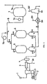
- (9) is an air compressor (10) is a drain separator, (11) is a Freon cooler, and (12) is a pair of adsorption cylinders.
- the adsorption cylinders (12) are filled with molecular sieves to adsorb and remove H 2 O and CO 2 in the air compressed by the air compressor (9).
- (13) is the 1st heat exchanger into which the compressed air after elimination of H 2 O and CO 2 by the adsorption cylinders (12) is supplied.
- (14) is the 2nd heat exchanger, into which the compressed air coming through the 1st heat exchanger is supplied.
- (15) is a rectifying column provided with a condenser (16) at the top to cool the compressed air cooled down to ultra low temperature by the 1st and 2nd heat exchangers (13, 14) still further, to turn a part of the compressed air into liquid to be kept on the bottom, and to take out nitrogen only in gas form.
- the rectifying column (15) functions to cool the compressed air cooled down to ultra low temperature (about -170°C) through the 1st and the 2nd heat exchangers (13, 14) further by passing through the liquefied air (18) (N 2 50 - 70%, O 2 30 - 50%) kept on the bottom of the rectifying column (15) by a pipe (17), then to jet the air inside through the expansion valve (19), and oxygen is liquefied by the condenser (16) and nitrogen is left in gas form.
- the condenser (16) comprises a heat exchanger (16c) in the condenser (16), to cool the heat exchanger (16c) with the liquefied air (18) from the bottom of the tower (22), supplied through valve (19), to return the liquefied portion of the compressed air to the tower (22).
- Liquefied nitrogen is supplied from the liquefied nitrogen tank (23) through pipe (24) to a liquid nitrogen holder X which accumulates reflux produced in the condenser (16).
- a level gauge (25) is provided to detect the level of liquefied air in the condenser (16) and adjust the valve (26) to control the supply of liquefied nitrogen from the liquefied nitrogen storage tank (23) into the column (15) according to the level of liquefied air in the condenser (16).
- the outlet pipe (27) is an outlet pipe to take out nitrogen gas from the part of the column (15) and functions to guide the nitrogen gas of ultra low temperature into the 2nd and 1st heat exchangers (14,13), to heat the gas to normal temperature by heat exchange with the compressed air supplied into the heat exchangers, and to feed into the main pipe (28).
- the outlet pipe (27) is provided with an oxygen adsorption cylinder (27a), which incorporate adsorbent that adsorbs oxygen and carbon monoxide selectively at ultra low temperature.
- the alternate long and short dash line shows a vacuum cooling box in which the heat exchangers (13,14) and the rectifying column (15) are housed and heat-insulated by vacuum perlite.
- (29) is the pipe to feed the gassified portion of the compressed air from the top of the condenser (16) into the 2nd and 1st heat exchangers (14,13), and (29a) is the pressure holding valve. After heat exchange (cooling of compressed air) in the 2nd and 1st heat exchangers (14,13), the air is discharged from the 1st heat exchanger (13) as indicated by the arrow A.
- (30) is the line of back-up system to feed the liquefied nitrogen in the liquefied nitrogen storage tank (23) into the main pipe (28) through evaporation of the evaporator (31) should the line of the air compression system go out of order
- (32) is an impurity analyzer to analyze the purity of the product nitrogen gas fed out to the main pipe. If the purity is low, the valves (34), (34a) are operated to discard the product nitrogen gas to the outside as shown by the arrow B.
- Nitrogen gas is produced by this apparatus through the following processes.
- Air is compressed by the air compressor (9) and moisture in the compressed air is removed by the drain separator (10), then the air is cooled by the Freon cooler (11), sent to the adsorption cylinders (12) as being cooled, and H 2 O and CO 2 in the air are removed by adsorption.
- the compressed air after removal of H 2 O and CO 2 is supplied into the 1st and 2nd heat exchangers (13) (14) to be cooled down to ultra low temperature, then is cooled further by the liquid air (18) stored at the bottom of the rectifying column (15) then is ejected into the tower (22) of the rectifying column (15).
- Oxygen in the air is liquefied by using the difference in the boiling point between nitrogen and oxygen (oxygen -183°C; nitrogen -196°C), nitrogen is taken out in gas form, supplied into the 1st or the 2nd heat exchanger (13 or 14) to be heated close to the normal temperature, then is taken out as nitrogen gas through the main pipe (28).
- the liquefied air from the bottom of the rectifying column (15) functions as the cooling source of the condenser (16).
- the liquefied nitrogen itself turns into gas and is supplied into the main pipe (28), mixed with the nitrogen gas in the air from the rectifying column (15), then is taken out as product nitrogen gas.
- the apparatus can produce highly pure nitrogen gas with 0.3 ppm or less of impurity oxygen by setting the rectifying column (15) at high purity since no expansion turbine is used unlike the case of conventional method.
- the nitrogen gas obtained contains oxygen of 5 ppm as impurity and by the nitrogen gas producing apparatus of PSA method, the obtained gas contains so much oxygen as 1000 ppm. Accordingly the apparatus, PSA type in particular, are not applicable as they are to electronic industry where highly pure nitrogen gas is required.
- the nitrogen gas obtained from the nitrogen gas producing apparatus of PSA type contains CO 2 gas of 5 to 10 ppm as impurity and another adsorption tank to remove CO 2 gas is necessary in addition.
- the nitrogen gas producing apparatus by the present invention, on the other hand, highly pure nitrogen gas which can be used for electronic industry as it is can be obtained. Moreover, the gas does not contain any CO 2 gas (eliminated by liquefaction within the producing apparatus), and there is no need to provide any adsorption tank for CO 2 gas separately.
- the condenser (16) of the rectifying column (15) a part of the nitrogen gas rising from the tower (22) and through a first connecting pipe (A') is liquefied and a part of the liquefied nitrogen pours back to the liquid nitrogen holder X in the tower (22) through a second connecting pipe (B') as reflux.
- feeding liquefied nitrogen gas of 100 Nm 3 from the liquefied nitrogen gas tank to the condenser (16) can obtain product nitrogen gas of 1000 Nm 3 . That is, the product nitrogen gas obtained is 10 times of the liquefied nitrogen supplied.
- the apparatus Compared with conventional nitrogen gas producing apparatus of PSA type or of low temperature separation type, the apparatus is simple and the whole system can be lower in cost, and reliability of the apparatus is higher as not many valves or no expansion turbine are required.
- nitrogen gas can be supplied even when the line of air compression system is out of order by the line of back-up system and supply of nitrogen gas is never interrupted.
- synthetic zeolite 3A, 4A or 5A having pore diameter of 3A, 4A or 5A molecular sieve 3A, 4A, or 5A made by Union Carbide
- synthetic zeolite 3A, 4A, and 5A respectively show highly selective adsorption property to oxygen and carbon monoxide at ultra low temperature.
- Synthetic Zeolite 13X of Union Carbide is also used in place of the said synthetic zeolite 3A, 4A or 5A.
- the nitrogen gas produced by gassification of the liquefied nitrogen in the nitrogen tank is also passed through the oxygen adsorption cylinder (11) in the same manner as the nitrogen gas obtained from compressed air. Even when the liquefied nitrogen in the nitrogen tank contains impurities such as oxygen and carbon monoxide, therefore, the purity of the obtained product nitrogen gas is not lowered. In this case, the quantity of oxygen and carbon monoxide in the ultra low temperature nitrogen gas guided into the oxygen adsorption cylinder (11) has been reduced to a low level while going through the rectifying column (15). Accordingly, the quantity of oxygen and carbon monoxide adsorbed in the cylinder (11) is minimal.
- One unit of adsorption cylinder suffices and regeneration of zeolite once a year is sufficient.
Landscapes
- Engineering & Computer Science (AREA)
- Physics & Mathematics (AREA)
- Mechanical Engineering (AREA)
- Thermal Sciences (AREA)
- General Engineering & Computer Science (AREA)
- Separation By Low-Temperature Treatments (AREA)
Claims (2)
- Appareil pour la production d'un azote gazeux de haute pureté comprenant un compresseur (9) destiné à comprimer l'air de provenance extérieure à l'appareil, un moyen (12) pour éliminer le gaz de dioxyde de carbone et l'eau de l'air comprimé, un échangeur de chaleur (13, 14) pour refroidir l'air comprimé à une température cryogénique, une colonne de rectification (15) pour séparer l'air en une portion d'air liquéfié et en vapeur d'azote, un stock d'azote liquide (23), une canalisation d'amenée (24) pour fournir l'azote liquide en provenance du stock d'azote liquide (23) à la portion supérieure de la colonne de rectification (15) en tant que réfrigérant, une canalisation de sortie (27) pour prélever l'azote de la portion supérieure de la colonne de rectification (15), et un condenseur (16) comprenant un échangeur de chaleur (16c) pour condenser la vapeur d'azote fournie à celui-ci par le dessus de la colonne de rectification (15) pour fournir un reflux d'azote liquide à la colonne (15) par échange thermique avec la portion d'air liquéfiant en évaporation fournie à l'échangeur de chaleur (16c) par une conduite reliant le condenseur (16) avec le fond de la colonne (15), le condenseur (16) étant formé pour accumuler la portion d'air liquéfié et un moyen de détection de niveau liquide (25) étant prévu de façon à détecter le niveau de portion d'air liquéfié dans le condenseur (16) et pour commander l'amenée d'azote liquide en provenance du stock (23) dans la colonne (15) en fonction de ce niveau, le stock d'azote liquide (23) étant apte à recevoir et à stocker l'azote liquide fournie depuis l'extérieur de l'appareil et de la colonne (15) et de l'échangeur de chaleur (13, 14) pour refroidir l'air comprimé contenu dans un caisson de refroidissement sous vide et isolé thermiquement par perlite sous vide.
- Appareil selon la revendication 1, comprenant de plus un cylindre d'absorption d'oxygène (27a) dans lequel est amené de l'azote par le canal de sortie (27).
Applications Claiming Priority (5)
| Application Number | Priority Date | Filing Date | Title |
|---|---|---|---|
| JP38050/83 | 1983-03-08 | ||
| JP58038050A JPS59164874A (ja) | 1983-03-08 | 1983-03-08 | 窒素ガス製造装置 |
| JP59004123A JPS60147086A (ja) | 1984-01-11 | 1984-01-11 | 高純度窒素ガス製造装置 |
| JP4123/84 | 1984-01-11 | ||
| EP84901096A EP0144430B1 (fr) | 1983-03-08 | 1984-03-07 | Appareil de production d'azote gazeux de purete elevee |
Related Parent Applications (2)
| Application Number | Title | Priority Date | Filing Date |
|---|---|---|---|
| EP84901096A Division EP0144430B1 (fr) | 1983-03-08 | 1984-03-07 | Appareil de production d'azote gazeux de purete elevee |
| EP84901096.2 Division | 1984-09-19 |
Publications (4)
| Publication Number | Publication Date |
|---|---|
| EP0279500A2 EP0279500A2 (fr) | 1988-08-24 |
| EP0279500A3 EP0279500A3 (en) | 1988-10-26 |
| EP0279500B1 EP0279500B1 (fr) | 1992-12-23 |
| EP0279500B2 true EP0279500B2 (fr) | 1998-11-04 |
Family
ID=27227518
Family Applications (1)
| Application Number | Title | Priority Date | Filing Date |
|---|---|---|---|
| EP88200470A Expired - Lifetime EP0279500B2 (fr) | 1983-03-08 | 1984-03-07 | Dispositif de production de gaz d'azote à haute pureté |
Country Status (1)
| Country | Link |
|---|---|
| EP (1) | EP0279500B2 (fr) |
Families Citing this family (4)
| Publication number | Priority date | Publication date | Assignee | Title |
|---|---|---|---|---|
| US4902321A (en) * | 1989-03-16 | 1990-02-20 | Union Carbide Corporation | Cryogenic rectification process for producing ultra high purity nitrogen |
| DE4017410A1 (de) * | 1989-06-02 | 1990-12-06 | Hitachi Ltd | Verfahren und vorrichtung zur herstellung von extrem reinem stickstoff |
| EP0908689A3 (fr) * | 1997-08-20 | 1999-06-23 | AIR LIQUIDE Japan, Ltd. | Procédé et dispositif de distillation d'air |
| CN113623943A (zh) * | 2021-08-22 | 2021-11-09 | 张家港市东南气体灌装有限公司 | 一种用于制造纯度不同的氮气的氮气制造系统及制造方法 |
Family Cites Families (2)
| Publication number | Priority date | Publication date | Assignee | Title |
|---|---|---|---|---|
| US3363427A (en) * | 1964-06-02 | 1968-01-16 | Air Reduction | Production of ultrahigh purity oxygen with removal of hydrocarbon impurities |
| GB1052146A (fr) * | 1965-02-26 | 1966-12-21 |
-
1984
- 1984-03-07 EP EP88200470A patent/EP0279500B2/fr not_active Expired - Lifetime
Also Published As
| Publication number | Publication date |
|---|---|
| EP0279500A2 (fr) | 1988-08-24 |
| EP0279500A3 (en) | 1988-10-26 |
| EP0279500B1 (fr) | 1992-12-23 |
Similar Documents
| Publication | Publication Date | Title |
|---|---|---|
| EP0144430B1 (fr) | Appareil de production d'azote gazeux de purete elevee | |
| US4671813A (en) | Highly pure nitrogen gas producing apparatus | |
| EP0191862B1 (fr) | Dispositif de production d'azote gazeux de grande purete | |
| US4668260A (en) | High-purity nitrogen gas production equipment | |
| JPH0313505B2 (fr) | ||
| EP0279500B2 (fr) | Dispositif de production de gaz d'azote à haute pureté | |
| JPS6158747B2 (fr) | ||
| US5058387A (en) | Process to ultrapurify liquid nitrogen imported as back-up for nitrogen generating plants | |
| US5546765A (en) | Air separating unit | |
| EP0756144B1 (fr) | Générateur de gaz pour la production d'azote de haute pureté | |
| JP2672250B2 (ja) | 高純度窒素ガス製造装置 | |
| JP3021389B2 (ja) | 高純度窒素ガス製造装置 | |
| JP2540243B2 (ja) | 高純度窒素ガス製造装置 | |
| JPS62116887A (ja) | 高純度窒素ガス製造装置 | |
| JPH0882476A (ja) | 高純度窒素ガス製造装置 | |
| JP2540244B2 (ja) | 窒素ガス製造装置 | |
| JPH0587447A (ja) | 窒素ガス製造装置 | |
| KR890000330B1 (ko) | 질소가스 제조장치 | |
| JPS6148071B2 (fr) | ||
| JPS6149594B2 (fr) | ||
| JPS6124969A (ja) | 高純度窒素ガス製造装置 | |
| JPS6152388B2 (fr) | ||
| JPH0719724A (ja) | 高純度窒素ガス製造装置 | |
| JPH0560460A (ja) | 高純度窒素および酸素ガス製造装置 | |
| JPS60232471A (ja) | 高純度窒素ガス製造装置 |
Legal Events
| Date | Code | Title | Description |
|---|---|---|---|
| PUAI | Public reference made under article 153(3) epc to a published international application that has entered the european phase |
Free format text: ORIGINAL CODE: 0009012 |
|
| AC | Divisional application: reference to earlier application |
Ref document number: 144430 Country of ref document: EP |
|
| AK | Designated contracting states |
Kind code of ref document: A2 Designated state(s): DE FR GB NL |
|
| PUAL | Search report despatched |
Free format text: ORIGINAL CODE: 0009013 |
|
| AK | Designated contracting states |
Kind code of ref document: A3 Designated state(s): DE FR GB NL |
|
| 17P | Request for examination filed |
Effective date: 19890405 |
|
| 17Q | First examination report despatched |
Effective date: 19900110 |
|
| GRAA | (expected) grant |
Free format text: ORIGINAL CODE: 0009210 |
|
| AC | Divisional application: reference to earlier application |
Ref document number: 144430 Country of ref document: EP |
|
| AK | Designated contracting states |
Kind code of ref document: B1 Designated state(s): DE FR GB NL |
|
| REF | Corresponds to: |
Ref document number: 3486017 Country of ref document: DE Date of ref document: 19930204 |
|
| ET | Fr: translation filed | ||
| PLBI | Opposition filed |
Free format text: ORIGINAL CODE: 0009260 |
|
| PLAB | Opposition data, opponent's data or that of the opponent's representative modified |
Free format text: ORIGINAL CODE: 0009299OPPO |
|
| 26 | Opposition filed |
Opponent name: LINDE AKTIENGESELLSCHAFT Effective date: 19930922 Opponent name: L'AIR LIQUIDE, S.A. POUR L'ETUDE ET L'EXPLOITATION Effective date: 19930921 |
|
| R26 | Opposition filed (corrected) |
Opponent name: L'AIR LIQUIDE, S.A. POUR L'ETUDE ET L'EXPLOITATION Effective date: 19930921 |
|
| NLR1 | Nl: opposition has been filed with the epo |
Opponent name: L'AIR LIQUIDE,S.A. |
|
| RAP2 | Party data changed (patent owner data changed or rights of a patent transferred) |
Owner name: DAIDO HOXAN INC. |
|
| NLT2 | Nl: modifications (of names), taken from the european patent patent bulletin |
Owner name: DAIDO HOXAN INC. |
|
| REG | Reference to a national code |
Ref country code: GB Ref legal event code: 732E |
|
| PLAW | Interlocutory decision in opposition |
Free format text: ORIGINAL CODE: EPIDOS IDOP |
|
| APAA | Appeal reference recorded |
Free format text: ORIGINAL CODE: EPIDOS REFN |
|
| APAC | Appeal dossier modified |
Free format text: ORIGINAL CODE: EPIDOS NOAPO |
|
| APAC | Appeal dossier modified |
Free format text: ORIGINAL CODE: EPIDOS NOAPO |
|
| APAC | Appeal dossier modified |
Free format text: ORIGINAL CODE: EPIDOS NOAPO |
|
| PLAW | Interlocutory decision in opposition |
Free format text: ORIGINAL CODE: EPIDOS IDOP |
|
| PUAH | Patent maintained in amended form |
Free format text: ORIGINAL CODE: 0009272 |
|
| STAA | Information on the status of an ep patent application or granted ep patent |
Free format text: STATUS: PATENT MAINTAINED AS AMENDED |
|
| 27A | Patent maintained in amended form |
Effective date: 19981104 |
|
| AK | Designated contracting states |
Kind code of ref document: B2 Designated state(s): DE FR GB NL |
|
| NLR2 | Nl: decision of opposition | ||
| ET3 | Fr: translation filed ** decision concerning opposition | ||
| NLR3 | Nl: receipt of modified translations in the netherlands language after an opposition procedure | ||
| NLS | Nl: assignments of ep-patents |
Owner name: DAIDO HOXAN INC. |
|
| NLT1 | Nl: modifications of names registered in virtue of documents presented to the patent office pursuant to art. 16 a, paragraph 1 |
Owner name: AIR WATER INC. |
|
| REG | Reference to a national code |
Ref country code: FR Ref legal event code: CD |
|
| REG | Reference to a national code |
Ref country code: GB Ref legal event code: IF02 |
|
| PGFP | Annual fee paid to national office [announced via postgrant information from national office to epo] |
Ref country code: GB Payment date: 20030305 Year of fee payment: 20 |
|
| PGFP | Annual fee paid to national office [announced via postgrant information from national office to epo] |
Ref country code: FR Payment date: 20030310 Year of fee payment: 20 |
|
| PGFP | Annual fee paid to national office [announced via postgrant information from national office to epo] |
Ref country code: DE Payment date: 20030320 Year of fee payment: 20 |
|
| PGFP | Annual fee paid to national office [announced via postgrant information from national office to epo] |
Ref country code: NL Payment date: 20030327 Year of fee payment: 20 |
|
| PG25 | Lapsed in a contracting state [announced via postgrant information from national office to epo] |
Ref country code: GB Free format text: LAPSE BECAUSE OF EXPIRATION OF PROTECTION Effective date: 20040306 |
|
| PG25 | Lapsed in a contracting state [announced via postgrant information from national office to epo] |
Ref country code: NL Free format text: LAPSE BECAUSE OF EXPIRATION OF PROTECTION Effective date: 20040307 |
|
| REG | Reference to a national code |
Ref country code: GB Ref legal event code: PE20 |
|
| NLV7 | Nl: ceased due to reaching the maximum lifetime of a patent |
Effective date: 20040307 |
|
| APAH | Appeal reference modified |
Free format text: ORIGINAL CODE: EPIDOSCREFNO |