EP0278931A2 - A bed structure for supporting engines and auxiliary units - Google Patents
A bed structure for supporting engines and auxiliary units Download PDFInfo
- Publication number
- EP0278931A2 EP0278931A2 EP88850029A EP88850029A EP0278931A2 EP 0278931 A2 EP0278931 A2 EP 0278931A2 EP 88850029 A EP88850029 A EP 88850029A EP 88850029 A EP88850029 A EP 88850029A EP 0278931 A2 EP0278931 A2 EP 0278931A2
- Authority
- EP
- European Patent Office
- Prior art keywords
- frame elements
- frame
- bed structure
- beams
- bed
- Prior art date
- Legal status (The legal status is an assumption and is not a legal conclusion. Google has not performed a legal analysis and makes no representation as to the accuracy of the status listed.)
- Granted
Links
- 238000002485 combustion reaction Methods 0.000 claims abstract description 5
- 230000000712 assembly Effects 0.000 description 4
- 238000000429 assembly Methods 0.000 description 4
- 238000009434 installation Methods 0.000 description 4
- 238000004519 manufacturing process Methods 0.000 description 2
- 230000001681 protective effect Effects 0.000 description 2
- 238000010276 construction Methods 0.000 description 1
- 230000008878 coupling Effects 0.000 description 1
- 238000010168 coupling process Methods 0.000 description 1
- 238000005859 coupling reaction Methods 0.000 description 1
- 238000005553 drilling Methods 0.000 description 1
- 239000000463 material Substances 0.000 description 1
- 238000000034 method Methods 0.000 description 1
- 239000005022 packaging material Substances 0.000 description 1
- 238000004806 packaging method and process Methods 0.000 description 1
- 229920006300 shrink film Polymers 0.000 description 1
- 238000003466 welding Methods 0.000 description 1
Images

Classifications
-
- F—MECHANICAL ENGINEERING; LIGHTING; HEATING; WEAPONS; BLASTING
- F16—ENGINEERING ELEMENTS AND UNITS; GENERAL MEASURES FOR PRODUCING AND MAINTAINING EFFECTIVE FUNCTIONING OF MACHINES OR INSTALLATIONS; THERMAL INSULATION IN GENERAL
- F16M—FRAMES, CASINGS OR BEDS OF ENGINES, MACHINES OR APPARATUS, NOT SPECIFIC TO ENGINES, MACHINES OR APPARATUS PROVIDED FOR ELSEWHERE; STANDS; SUPPORTS
- F16M5/00—Engine beds, i.e. means for supporting engines or machines on foundations
-
- H—ELECTRICITY
- H02—GENERATION; CONVERSION OR DISTRIBUTION OF ELECTRIC POWER
- H02K—DYNAMO-ELECTRIC MACHINES
- H02K5/00—Casings; Enclosures; Supports
- H02K5/26—Means for adjusting casings relative to their supports
-
- B—PERFORMING OPERATIONS; TRANSPORTING
- B65—CONVEYING; PACKING; STORING; HANDLING THIN OR FILAMENTARY MATERIAL
- B65D—CONTAINERS FOR STORAGE OR TRANSPORT OF ARTICLES OR MATERIALS, e.g. BAGS, BARRELS, BOTTLES, BOXES, CANS, CARTONS, CRATES, DRUMS, JARS, TANKS, HOPPERS, FORWARDING CONTAINERS; ACCESSORIES, CLOSURES, OR FITTINGS THEREFOR; PACKAGING ELEMENTS; PACKAGES
- B65D85/00—Containers, packaging elements or packages, specially adapted for particular articles or materials
- B65D85/68—Containers, packaging elements or packages, specially adapted for particular articles or materials for machines, engines or vehicles in assembled or dismantled form
-
- F—MECHANICAL ENGINEERING; LIGHTING; HEATING; WEAPONS; BLASTING
- F16—ENGINEERING ELEMENTS AND UNITS; GENERAL MEASURES FOR PRODUCING AND MAINTAINING EFFECTIVE FUNCTIONING OF MACHINES OR INSTALLATIONS; THERMAL INSULATION IN GENERAL
- F16M—FRAMES, CASINGS OR BEDS OF ENGINES, MACHINES OR APPARATUS, NOT SPECIFIC TO ENGINES, MACHINES OR APPARATUS PROVIDED FOR ELSEWHERE; STANDS; SUPPORTS
- F16M3/00—Portable or wheeled frames or beds, e.g. for emergency power-supply aggregates, compressor sets
-
- B—PERFORMING OPERATIONS; TRANSPORTING
- B65—CONVEYING; PACKING; STORING; HANDLING THIN OR FILAMENTARY MATERIAL
- B65D—CONTAINERS FOR STORAGE OR TRANSPORT OF ARTICLES OR MATERIALS, e.g. BAGS, BARRELS, BOTTLES, BOXES, CANS, CARTONS, CRATES, DRUMS, JARS, TANKS, HOPPERS, FORWARDING CONTAINERS; ACCESSORIES, CLOSURES, OR FITTINGS THEREFOR; PACKAGING ELEMENTS; PACKAGES
- B65D2585/00—Containers, packaging elements or packages specially adapted for particular articles or materials
- B65D2585/68—Containers, packaging elements or packages specially adapted for particular articles or materials for machines, engines, or vehicles in assembled or dismantled form
- B65D2585/6802—Containers, packaging elements or packages specially adapted for particular articles or materials for machines, engines, or vehicles in assembled or dismantled form specific machines, engines or vehicles
- B65D2585/6875—Containers, packaging elements or packages specially adapted for particular articles or materials for machines, engines, or vehicles in assembled or dismantled form specific machines, engines or vehicles engines, motors, machines and vehicle parts
- B65D2585/6877—Containers, packaging elements or packages specially adapted for particular articles or materials for machines, engines, or vehicles in assembled or dismantled form specific machines, engines or vehicles engines, motors, machines and vehicle parts engines or motors
Definitions
- the present invention relates to a bed structure intended for supporting driving and driven units, such as internal combustion engines and generators for example, and comprising first frame elements having support surfaces for supporting at least one such unit.
- Stationary internal combustion engines intended for driving e.g. generators, pumps, rotary machines, and like auxiliaries
- generators e.g. generators, pumps, rotary machines, and like auxiliaries
- This manufacture will then either dismantle the engine from the frame structure and fit the engine to his own engine and generator support bed, or alternatively will utilize the original frame structure as an engine support bed and mount the generator on a separate support bed which is aligned with and connected to the engine bed.
- the object of the present invention is to provide a bed structure of the kind defined in the introduction which can be used as a supporting frame structure for transportation purposes, as an engine support bed, and as a bed for supporting an auxiliary unit, e.g. a generator, while at the same time eliminating the need to package the engine in a wooden crate.
- a bed structure of the kind defined in the introduction which can be used as a supporting frame structure for transportation purposes, as an engine support bed, and as a bed for supporting an auxiliary unit, e.g. a generator, while at the same time eliminating the need to package the engine in a wooden crate.
- second frame elements which present support surfaces for supporting at least one further unit intended for connection to the first mentioned unit, are so connected to the first frame elements as to be adjustable to a transportation mode in which the greater part of said second frame elements is located within the extremities of the horizontal extension of the first frame elements, and to an operational mode in which said second frame elements form an extension of the first frame elements and that at least one of the frame elements present means with which the lifting tines of a fork-lift device are able to engage for the purpose of lifting the bed structure with a unit mounted thereon.
- an engine manufacturer is able to utilize the bed structure formed by the first frame elements as a support means in the assemblage of engines and auxiliary parts. Subsequent to this assemblage, the bed structure is used as a loading pallet, by engaging the tines of a fork-lift device directly with means provided herefor on the bed structure. This eliminates the need for separate loading pallets, crates or trestles. Since in the transportation mode of the bed structure the second frame elements are contained fully within the outer confines of the first frame elements, or extend from said first frame elements only to a slight extent, the whole assembly can be packaged in shrink film such as to provide a protective covering during transportation of the assembly to the customer.
- the customer need only extend the second frame elements to the extent dictated by the auxiliary unit to be supported, e.g. a generator, and to secure the first and second frame elements together, e.g. by welding or with the aid of bolts, whereafter the generator can be fitted on the bed and connected to the engine.
- the auxiliary unit e.g. a generator
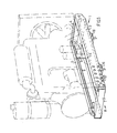
- Figure 1 is a perspective view of a first embodiment of an inventive bed structure in a transportation mode
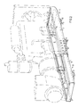
- Figure 2 shows the bed structure of Fig 1 in an extended state
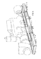
- Figure 3 is a perspective view of a second embodiment of a bed structure with said bed structure in an extended state
- Figure 4 is a perspective view of a third embodiment of a bed structure in a transportation mode
- Figure 5 is a perspective view of a fourth embodiment of a bed structure in a transportation mode
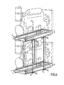
- Figure 6 is a perspective view of two bed structures interconnected by stack up means.
- the reference numeral 1 identifies a frame structure which has firmly mounted thereon a diesel engine and a radiator, shown in chain lines.
- the frame structure 1 comprises a pair of U-beams 2 which extend in the direction of the longitudinal axis of the engine, a pair of transverse U-beams 3, and an end piece 4, all of which are welded or bolted together to form a rigid frame.
- the upper surface 5 of the U-beams 2 provides supports for the engine.
- the U-beams 2 have inserted telescopically thereinto a pair of U-beams 6 (Fig 1) which are joined together by means of an end piece 7 and which form a frame section, which is identified generally by reference numeral 8.
- the beams 6 are held against sideways movement by a pair of plates 9 attached to each beam 2.
- the frame section 8 is shown extended somewhat from the frame section 1 such as to form a bed for an auxiliary unit, which in the illustrated embodiment has the form of a generator shown in chain lines.
- the beams 6 are secured to the beams 2, for instance by drilling in the beams 6 holes which correspond to the holes 10 provided in the beams 2 and bolting or riveting the beams together, or alternatively by forming a weld in the holes 10.
- the embodiment of Figures 1 and 2 also incorporates a loose cross-beam 11 which is secured or welded firmly to the beam 6 subsequent to extending said beams from the pair of beams 2.
- the cross-beam 11 may be adjacent to or in the proximity of the outer ends of respective beams 6 prior to delivery of the engine assembly to the customer.
- FIG. 3 illustrates an embodiment of the inventive bed which includes, in addition to the frame sections 1 and 8, a third frame section 12.
- This third frame section corresponds to the frame section 8 and comprises a pair of beams 13 which extend in the direction of the longitudinal axis of the frame structure, an end piece 14 and a transverse beam 15.
- the inner ends of the beams 6 and 13 meet when the frame sections 8 and 12 are pushed into the beam pair 2 to their full extent, which means that their outer ends will project slightly from respective ends of the beams 2, unless the length of the frame section 1 is at least equal to the sum of the lengths of the frame sections 8 and 12.
- the frame section 1 is shorter than the total length of frame sections 8 and 12, either the frame section 8 or the frame section 12 may be made narrower than the other, such as to enable said sections to overlap one another in an inserted or retracted position, i.e. for instance such that the beams 13 can be moved axially within the U-beams 6.
- the frame section 12 forms a bed for a hydraulic pump which is connected to a power take-off located on the front of the engine.
- This embodiment can also be used, for example, to support a centrally positioned generator which is driven directly from an engine located on one side thereof and which is supplied with "auxiliary power" from the other side thereof through the intermediary of a hydraulic coupling.
- the transverse U-beams 3 of the frame section 1 are secured in spaced relationship to the beams 2 at a mutual distance apart which is adapted to the distance between the tines of a fork-lift truck.
- the open faces or respective beams 3 are turned towards the open faces of the beams 2, such as to form closed sleeve-like structures 16 for accommodating the lifting tines of said truck, therewith to afford a safe and reliable lifting arrangement.
- Figure 4 discloses an embodiment of the inventive bed similar to that shown in Fig 1 but having the frame section 8 joined to the frame section 1 by hinge means 20.
- the frame section 8 is folded down under the frame section 1.
- the U-beams 3, which form the sleeve structures 16 for the lifting tines of a truck, are therefore welded to the frame structure 8 instead of the frame 1.
- Figure 5 discloses another embodiment of the inventive bed having hinge means 20 between the frame section 1 and the frame section 8.
- a third frame section 12 similar to that shown in Fig 3 is joined to the frame section 1 by hinge means 21.
- the frame sections 8 and 12 are folded upwards to the transportation position, as shown with solid lines in Fig 5.
- the extended working position is indicated with broken lines.
- the end surfaces 22 could be provided with means forming supports for other frame and engine assemblies so as to make it possible to stack frame and engine assemblies on top of one another similar to what is shown in Figure 6.
- Means (not shown) are provided to lock the frame sections 8 and 12 in their upright position.
- the frame assembly according to the invention may be utilized for other installations than stationary installations of the diesel power plan kind or like installations.
- the frame assembly can be used for marine purposes, such as to enable a marine engine which is mounted for transportation on the frame assembly to be winched down into a small confined engine room, with the frame section 1 forming an engine bed or a part thereof.
- the frame assembly can then be extended in the aforedescribed manner, so that the frame section 8 and/or the frame section 12 form a support bed for hydraulic motors, reversing gear assemblies, etc.
- the basic concept of the invention thus resides in the use of one and the same bed/frame assembly as a means for supporting an engine during its assembly, as a means for supporting the engine and at least as a part of the engine packaging material during transportation of the engine, and as a permanent means for supporting an engine and auxiliaries in the final installation thereof.
- the aforedescribed respective arrangements for enabling the frame assembly to be lifted by means of lifting forks and to enable the frame assembly to be extended are the minimum facilities required to this end.
- Other arrangements are also conceivable in addition hereto, in order to increase the versatility of the inventive bed structure.
- the frame section 1 may be provided with attachment points (not shown) for a framework on which a protective covering, e.g.
- the bed structure may be provided with devices (not shown) which can be adapted to the transport arrangements provided on the actual assembly or construction line concerned.
- a stackable system devoid of shelves can be created (Fig 6) with the aid of cramp-like bracing struts 23 inserted into the respective sleeves 16 of the frame assembly of an overlying engine and an underlying frame assembly with engine.
Landscapes
- Engineering & Computer Science (AREA)
- General Engineering & Computer Science (AREA)
- Mechanical Engineering (AREA)
- Power Engineering (AREA)
- Packaging Of Machine Parts And Wound Products (AREA)
- Forklifts And Lifting Vehicles (AREA)
- Valve-Gear Or Valve Arrangements (AREA)
- Threshing Machine Elements (AREA)
- Connection Of Motors, Electrical Generators, Mechanical Devices, And The Like (AREA)
- Automatic Cycles, And Cycles In General (AREA)
- Input Circuits Of Receivers And Coupling Of Receivers And Audio Equipment (AREA)
- Fittings On The Vehicle Exterior For Carrying Loads, And Devices For Holding Or Mounting Articles (AREA)
- Vehicle Step Arrangements And Article Storage (AREA)
- Pinball Game Machines (AREA)
- Types And Forms Of Lifts (AREA)
- Vending Machines For Individual Products (AREA)
- Invalid Beds And Related Equipment (AREA)
- Testing Of Engines (AREA)
- Body Structure For Vehicles (AREA)
Abstract
Description
- The present invention relates to a bed structure intended for supporting driving and driven units, such as internal combustion engines and generators for example, and comprising first frame elements having support surfaces for supporting at least one such unit.
- Stationary internal combustion engines intended for driving, e.g. generators, pumps, rotary machines, and like auxiliaries, are normally mounted on a supporting frame structure and then encased in large wooden crates for transportation from the manufacturer to the customer, e.g. to a manufacturer of generator units that are driven by an internal combustion engine. This manufacture will then either dismantle the engine from the frame structure and fit the engine to his own engine and generator support bed, or alternatively will utilize the original frame structure as an engine support bed and mount the generator on a separate support bed which is aligned with and connected to the engine bed.
- The packaging of engines on support frames in large wooden crates and the transportation of such crated assemblies are expensive for several reasons. Firstly the crates themselves are expensive and bulky, and secondly the material work expended cannot be put to any purpose other than that associated purely with transporation, particularly when the transporting support frame is not subsequently used as the engine bed.
- The object of the present invention is to provide a bed structure of the kind defined in the introduction which can be used as a supporting frame structure for transportation purposes, as an engine support bed, and as a bed for supporting an auxiliary unit, e.g. a generator, while at the same time eliminating the need to package the engine in a wooden crate.
- This object is achieved in accordance with the invention in that second frame elements, which present support surfaces for supporting at least one further unit intended for connection to the first mentioned unit, are so connected to the first frame elements as to be adjustable to a transportation mode in which the greater part of said second frame elements is located within the extremities of the horizontal extension of the first frame elements, and to an operational mode in which said second frame elements form an extension of the first frame elements and that at least one of the frame elements present means with which the lifting tines of a fork-lift device are able to engage for the purpose of lifting the bed structure with a unit mounted thereon.
- During the process of manufacture, an engine manufacturer is able to utilize the bed structure formed by the first frame elements as a support means in the assemblage of engines and auxiliary parts. Subsequent to this assemblage, the bed structure is used as a loading pallet, by engaging the tines of a fork-lift device directly with means provided herefor on the bed structure. This eliminates the need for separate loading pallets, crates or trestles. Since in the transportation mode of the bed structure the second frame elements are contained fully within the outer confines of the first frame elements, or extend from said first frame elements only to a slight extent, the whole assembly can be packaged in shrink film such as to provide a protective covering during transportation of the assembly to the customer. The customer need only extend the second frame elements to the extent dictated by the auxiliary unit to be supported, e.g. a generator, and to secure the first and second frame elements together, e.g. by welding or with the aid of bolts, whereafter the generator can be fitted on the bed and connected to the engine.
- The invention will now be described with reference to exemplifying embodiments thereof illustrated in the accompanying drawings, in which Figure 1 is a perspective view of a first embodiment of an inventive bed structure in a transportation mode; Figure 2 shows the bed structure of Fig 1 in an extended state; Figure 3 is a perspective view of a second embodiment of a bed structure with said bed structure in an extended state; Figure 4 is a perspective view of a third embodiment of a bed structure in a transportation mode; Figure 5 is a perspective view of a fourth embodiment of a bed structure in a transportation mode; and Figure 6 is a perspective view of two bed structures interconnected by stack up means.
- In Figure 1 the
reference numeral 1 identifies a frame structure which has firmly mounted thereon a diesel engine and a radiator, shown in chain lines. Theframe structure 1 comprises a pair ofU-beams 2 which extend in the direction of the longitudinal axis of the engine, a pair oftransverse U-beams 3, and an end piece 4, all of which are welded or bolted together to form a rigid frame. The upper surface 5 of the U-beams 2 provides supports for the engine. - The
U-beams 2 have inserted telescopically thereinto a pair of U-beams 6 (Fig 1) which are joined together by means of anend piece 7 and which form a frame section, which is identified generally byreference numeral 8. Thebeams 6 are held against sideways movement by a pair ofplates 9 attached to eachbeam 2. - In Figure 2 the
frame section 8 is shown extended somewhat from theframe section 1 such as to form a bed for an auxiliary unit, which in the illustrated embodiment has the form of a generator shown in chain lines. Subsequent to extending the frame section sufficiently to accommodate the auxiliary unit, thebeams 6 are secured to thebeams 2, for instance by drilling in thebeams 6 holes which correspond to theholes 10 provided in thebeams 2 and bolting or riveting the beams together, or alternatively by forming a weld in theholes 10. The embodiment of Figures 1 and 2 also incorporates aloose cross-beam 11 which is secured or welded firmly to thebeam 6 subsequent to extending said beams from the pair ofbeams 2. When circumstances permit thebeams 6 to project slightly from thebeams 2 in the transport condition of the frame structure, thecross-beam 11 may be adjacent to or in the proximity of the outer ends ofrespective beams 6 prior to delivery of the engine assembly to the customer. - Figure 3 illustrates an embodiment of the inventive bed which includes, in addition to the
frame sections third frame section 12. This third frame section corresponds to theframe section 8 and comprises a pair ofbeams 13 which extend in the direction of the longitudinal axis of the frame structure, an end piece 14 and atransverse beam 15. In the case of the illustrated embodiment, the inner ends of thebeams frame sections beam pair 2 to their full extent, which means that their outer ends will project slightly from respective ends of thebeams 2, unless the length of theframe section 1 is at least equal to the sum of the lengths of theframe sections - If the
frame section 1 is shorter than the total length offrame sections frame section 8 or theframe section 12 may be made narrower than the other, such as to enable said sections to overlap one another in an inserted or retracted position, i.e. for instance such that thebeams 13 can be moved axially within theU-beams 6. In the extended state illustrated in Fig. 3, theframe section 12 forms a bed for a hydraulic pump which is connected to a power take-off located on the front of the engine. This embodiment can also be used, for example, to support a centrally positioned generator which is driven directly from an engine located on one side thereof and which is supplied with "auxiliary power" from the other side thereof through the intermediary of a hydraulic coupling. - The
transverse U-beams 3 of theframe section 1 are secured in spaced relationship to thebeams 2 at a mutual distance apart which is adapted to the distance between the tines of a fork-lift truck. The open faces orrespective beams 3 are turned towards the open faces of thebeams 2, such as to form closed sleeve-like structures 16 for accommodating the lifting tines of said truck, therewith to afford a safe and reliable lifting arrangement. - Figure 4 discloses an embodiment of the inventive bed similar to that shown in Fig 1 but having the
frame section 8 joined to theframe section 1 by hinge means 20. In the disclosed transportation mode theframe section 8 is folded down under theframe section 1. TheU-beams 3, which form thesleeve structures 16 for the lifting tines of a truck, are therefore welded to theframe structure 8 instead of theframe 1. - Figure 5 discloses another embodiment of the inventive bed having hinge means 20 between the
frame section 1 and theframe section 8. In addition, athird frame section 12 similar to that shown in Fig 3 is joined to theframe section 1 by hinge means 21. In this embodiment theframe sections end surfaces 22 could be provided with means forming supports for other frame and engine assemblies so as to make it possible to stack frame and engine assemblies on top of one another similar to what is shown in Figure 6. Means (not shown) are provided to lock theframe sections - It will be appreciated that the frame assembly according to the invention may be utilized for other installations than stationary installations of the diesel power plan kind or like installations. For example, the frame assembly can be used for marine purposes, such as to enable a marine engine which is mounted for transportation on the frame assembly to be winched down into a small confined engine room, with the
frame section 1 forming an engine bed or a part thereof. The frame assembly can then be extended in the aforedescribed manner, so that theframe section 8 and/or theframe section 12 form a support bed for hydraulic motors, reversing gear assemblies, etc. - The basic concept of the invention thus resides in the use of one and the same bed/frame assembly as a means for supporting an engine during its assembly, as a means for supporting the engine and at least as a part of the engine packaging material during transportation of the engine, and as a permanent means for supporting an engine and auxiliaries in the final installation thereof. The aforedescribed respective arrangements for enabling the frame assembly to be lifted by means of lifting forks and to enable the frame assembly to be extended are the minimum facilities required to this end. Other arrangements are also conceivable in addition hereto, in order to increase the versatility of the inventive bed structure. For example, the
frame section 1 may be provided with attachment points (not shown) for a framework on which a protective covering, e.g. made of shrink plastic is fitted. Furthermore, the bed structure may be provided with devices (not shown) which can be adapted to the transport arrangements provided on the actual assembly or construction line concerned. In addition, a stackable system devoid of shelves can be created (Fig 6) with the aid of cramp-like bracing struts 23 inserted into therespective sleeves 16 of the frame assembly of an overlying engine and an underlying frame assembly with engine. - Although the invention has been described with reference to frame assembly embodiments which can be extended in the direction of the longitudinal axis of the engine, it will be understood that the invention also includes embodiments, not shown, in which the bed/frame assembly can be extended in a direction other than in the direction of the longitudinal axis of the unit carried thereby, e.g. such as to accommodate laterally located belt-driven or gear-driven auxiliary units.
Claims (7)
Priority Applications (1)
| Application Number | Priority Date | Filing Date | Title |
|---|---|---|---|
| AT88850029T ATE73916T1 (en) | 1987-02-09 | 1988-01-25 | SUPPORT FRAME FOR ENGINES AND AUXILIARY DEVICES. |
Applications Claiming Priority (2)
| Application Number | Priority Date | Filing Date | Title |
|---|---|---|---|
| SE8700482A SE466967B (en) | 1987-02-09 | 1987-02-09 | BAEDD MOVES ENGINES WITH ADDITIONAL DEVICE |
| SE8700482 | 1987-02-09 |
Publications (3)
| Publication Number | Publication Date |
|---|---|
| EP0278931A2 true EP0278931A2 (en) | 1988-08-17 |
| EP0278931A3 EP0278931A3 (en) | 1988-10-05 |
| EP0278931B1 EP0278931B1 (en) | 1992-03-18 |
Family
ID=20367438
Family Applications (1)
| Application Number | Title | Priority Date | Filing Date |
|---|---|---|---|
| EP88850029A Expired - Lifetime EP0278931B1 (en) | 1987-02-09 | 1988-01-25 | A bed structure for supporting engines and auxiliary units |
Country Status (13)
| Country | Link |
|---|---|
| US (1) | US5085396A (en) |
| EP (1) | EP0278931B1 (en) |
| JP (1) | JP2569106B2 (en) |
| KR (1) | KR970005497B1 (en) |
| CN (1) | CN1012278B (en) |
| AT (1) | ATE73916T1 (en) |
| AU (1) | AU611881B2 (en) |
| BR (1) | BR8800467A (en) |
| CA (1) | CA1304063C (en) |
| DE (1) | DE3869153D1 (en) |
| ES (1) | ES2030903T3 (en) |
| IN (1) | IN172179B (en) |
| SE (1) | SE466967B (en) |
Cited By (6)
| Publication number | Priority date | Publication date | Assignee | Title |
|---|---|---|---|---|
| DE3921879A1 (en) * | 1989-07-04 | 1991-01-17 | Motoren Werke Mannheim Ag | POWER AND HEAT COUPLING SYSTEM |
| FR2712035A1 (en) * | 1993-11-03 | 1995-05-12 | Knf Neuberger Gmbh | Pump support equipped with a pump. |
| FR2725006A1 (en) * | 1994-09-22 | 1996-03-29 | Jean Michel Auguste Claude | Energy supply detachable chassis for towing trailer |
| US5697249A (en) * | 1994-09-09 | 1997-12-16 | Kawasaki Jukogyo Kabushiki Kaisha | Portable drive unit |
| AT410019B (en) * | 2000-01-19 | 2003-01-27 | Jenbacher Ag | MOTOR GENERATOR ARRANGEMENT |
| US20170254468A1 (en) * | 2016-03-02 | 2017-09-07 | Cummins Power Generation Limited | Mounting chassis for genset with reduced clearance |
Families Citing this family (33)
| Publication number | Priority date | Publication date | Assignee | Title |
|---|---|---|---|---|
| US5396791A (en) * | 1993-08-13 | 1995-03-14 | General Electric Company | Engine testing mounting adaptor |
| US5848778A (en) * | 1995-11-29 | 1998-12-15 | Wagner; James W. | Engine block mount |
| USD400081S (en) | 1997-06-09 | 1998-10-27 | Eagle Technology & Manufacturing, Inc. | Angle bracket fixture |
| US5975480A (en) * | 1997-08-14 | 1999-11-02 | Millennium Technologies, Inc. | Motor mount |
| US6099267A (en) * | 1998-05-08 | 2000-08-08 | Ingersoll-Rand Company | Stand for a fluid compressor having an extending and rotating movable starter box base plate |
| US6171540B1 (en) | 1998-05-27 | 2001-01-09 | Eagle Technology & Mfg., Inc. | Method of making a plastic angle bracket |
| JP2000108813A (en) * | 1998-10-02 | 2000-04-18 | Honda Motor Co Ltd | Vehicle front structure |
| US6155662A (en) * | 1999-06-04 | 2000-12-05 | Haworth, Inc. | Universal wall support for a cabinet |
| USD455244S1 (en) | 2001-03-12 | 2002-04-02 | Donald C. Laustrup | Spool rack |
| KR100489803B1 (en) * | 2001-11-19 | 2005-05-16 | 대우조선해양 주식회사 | Method for manufacturing a main support to the turbine of ship |
| US7028970B1 (en) * | 2004-04-13 | 2006-04-18 | Wiseman Michael D | Adjustable position mounting device |
| GB2414062B (en) * | 2004-05-15 | 2006-09-06 | Hansen Transmissions Int | Motor and gear unit assembly |
| DE102005045605A1 (en) * | 2005-09-23 | 2007-04-05 | Siemens Ag | Inserting method e.g. for rail-mounted vehicle component within rail-mounted vehicle, involves inserting rail-mounted vehicle component within vehicle, such as traction vehicle with transportation fork raises component |
| US7543793B2 (en) * | 2005-12-21 | 2009-06-09 | Graham Wayne A | Generator set tank and enclosure with adjustable mounting system |
| CN100463834C (en) * | 2006-12-06 | 2009-02-25 | 宁波市北仑海伯精密机械制造有限公司 | Fast chucking unit for propeller pedestal |
| US20090100918A1 (en) * | 2007-09-26 | 2009-04-23 | United Technologies Corp. | Systems and Methods for Testing Gas Turbine Engines |
| US8851863B2 (en) * | 2009-01-16 | 2014-10-07 | ETTER Engineering Company, Inc. | Gas booster system and related method |
| DE102009007563B4 (en) * | 2009-02-04 | 2014-12-18 | Sew-Eurodrive Gmbh & Co Kg | driving device |
| EP2773895B1 (en) * | 2011-11-01 | 2017-06-28 | Cummins Power Generation Inc. | Modular skid base |
| ITFI20120114A1 (en) * | 2012-06-08 | 2013-12-09 | Nuovo Pignone Srl | "MODULAR GAS PLANT TURBINE WITH A HEAVY DUTY GAS TURBINE" |
| RU121904U1 (en) * | 2012-06-18 | 2012-11-10 | Рационал Энерги Зюстеме Гмбх | BOILER EQUIPMENT SYSTEM, AND ALSO COMPONENT AND CONSTRUCTION ELEMENTS OF SUCH SYSTEM |
| CN103233812A (en) * | 2013-05-09 | 2013-08-07 | 广西玉林卓越动力发电设备有限公司 | Diesel generator set capable of improving installing efficiency and running stability |
| CN103363252B (en) * | 2013-08-01 | 2015-04-29 | 太仓成铭液压机械有限公司 | Machine bottom plate |
| CN107407456B (en) * | 2015-03-13 | 2019-05-28 | 索尤若驱动有限及两合公司 | Driving assembly |
| US9551451B2 (en) * | 2015-04-01 | 2017-01-24 | Electro-Motive Diesel, Inc. | Skid structure for a powertrain |
| US10305350B2 (en) * | 2016-11-18 | 2019-05-28 | Cummins Power Generation Limited | Generator set integrated gearbox |
| US10378231B1 (en) | 2017-11-22 | 2019-08-13 | United Staging & Rigging, LLC | Ballasted attachment for temporary truss structures |
| US10288212B1 (en) * | 2018-02-19 | 2019-05-14 | Mantosh Isanchandra Bhattacharya | Tunable support frame structure for rotating machines |
| CN108880071B (en) * | 2018-06-08 | 2020-05-12 | 山东众音化学科技有限公司 | Cooling motor |
| US10934931B2 (en) | 2018-06-22 | 2021-03-02 | Cummins Power Generation Limited | Integrated epicyclic gearbox and alternator |
| KR102118878B1 (en) * | 2018-10-19 | 2020-06-04 | 윤동욱 | Supporting device for easy attachment and detachment of equipment |
| DE112020004942T5 (en) | 2019-10-14 | 2022-09-01 | MTU Onsite Energy Corporation | Guide Mechanisms for Modular Generator Set System |
| CN114216004B (en) * | 2021-12-20 | 2022-12-02 | 苏州芭雅卡机电有限公司 | Separated damping type mobile generator |
Family Cites Families (18)
| Publication number | Priority date | Publication date | Assignee | Title |
|---|---|---|---|---|
| US2204877A (en) * | 1939-05-29 | 1940-06-18 | American Well & Prospecting Co | Adjustable engine skid |
| GB627875A (en) * | 1945-12-05 | 1949-08-17 | Lee C Moore And Company Inc | Improvements in or relating to an engine foundation |
| US2592845A (en) * | 1949-10-31 | 1952-04-15 | Moto Sway Corp | Chassis supporting structure for vehicle lifts |
| BE548432A (en) * | 1955-06-29 | |||
| GB896733A (en) * | 1959-07-29 | 1962-05-16 | John Thomas & Co Pty Ltd | Improvements in pallets for use with fork lift trucks and the like |
| GB1024294A (en) * | 1962-12-13 | 1966-03-30 | Howe And Sons Ltd T | Improvements in or relating to load handling pallets |
| US3391445A (en) * | 1965-06-28 | 1968-07-09 | Youngstown Steel Door Co | Method of fabricating railroad car sides |
| US3446366A (en) * | 1967-04-19 | 1969-05-27 | Norman H Miller | Maintenance lift |
| US3891345A (en) * | 1973-11-23 | 1975-06-24 | Worthington Pump Int | Supporting foot means for a separately coupled centrifugal pump |
| FR2301443A1 (en) * | 1975-02-19 | 1976-09-17 | Pouyaud Andre | Container base frame made from box beams - receives pinned handling beams in box beams and has feet welded to lower corner plates |
| US4123038A (en) * | 1977-07-15 | 1978-10-31 | Meyers Gilbert D | Wheel lift |
| US4191356A (en) * | 1978-06-08 | 1980-03-04 | Caterpillar Tractor Co. | Engine mounting base |
| SE412543B (en) * | 1978-07-31 | 1980-03-10 | Ossbahr C | DEVICE FOR PRESENT COSTALING OF MACHINE AND FOUNDATION MODULES |
| GB2112922A (en) * | 1981-12-18 | 1983-07-27 | Channel Aire Offshore Services | Engine cooling system |
| US4511112A (en) * | 1982-03-22 | 1985-04-16 | Chrysler Corporation | Engine test stand |
| DE3307923C2 (en) * | 1983-03-05 | 1986-06-19 | Klein, Schanzlin & Becker Ag, 6710 Frankenthal | Base plate for machine units |
| DE8528471U1 (en) * | 1985-10-05 | 1985-11-28 | Pohle + Rehling Gmbh, 4353 Oer-Erkenschwick | Transport container for replacement motors |
| US4638971A (en) * | 1986-02-04 | 1987-01-27 | Dowell Schlumberger Incorporated | Machinery skid |
-
1987
- 1987-02-09 SE SE8700482A patent/SE466967B/en not_active IP Right Cessation
-
1988
- 1988-01-25 EP EP88850029A patent/EP0278931B1/en not_active Expired - Lifetime
- 1988-01-25 ES ES198888850029T patent/ES2030903T3/en not_active Expired - Lifetime
- 1988-01-25 DE DE8888850029T patent/DE3869153D1/en not_active Expired - Lifetime
- 1988-01-25 AT AT88850029T patent/ATE73916T1/en not_active IP Right Cessation
- 1988-01-29 IN IN80/DEL/88A patent/IN172179B/en unknown
- 1988-02-01 AU AU11147/88A patent/AU611881B2/en not_active Ceased
- 1988-02-04 US US07/159,419 patent/US5085396A/en not_active Expired - Fee Related
- 1988-02-05 BR BR8800467A patent/BR8800467A/en not_active IP Right Cessation
- 1988-02-08 CA CA000558344A patent/CA1304063C/en not_active Expired - Lifetime
- 1988-02-08 KR KR1019880001145A patent/KR970005497B1/en not_active Expired - Fee Related
- 1988-02-09 CN CN88100638A patent/CN1012278B/en not_active Expired
- 1988-02-09 JP JP63028605A patent/JP2569106B2/en not_active Expired - Lifetime
Cited By (11)
| Publication number | Priority date | Publication date | Assignee | Title |
|---|---|---|---|---|
| DE3921879A1 (en) * | 1989-07-04 | 1991-01-17 | Motoren Werke Mannheim Ag | POWER AND HEAT COUPLING SYSTEM |
| FR2712035A1 (en) * | 1993-11-03 | 1995-05-12 | Knf Neuberger Gmbh | Pump support equipped with a pump. |
| US5697249A (en) * | 1994-09-09 | 1997-12-16 | Kawasaki Jukogyo Kabushiki Kaisha | Portable drive unit |
| FR2725006A1 (en) * | 1994-09-22 | 1996-03-29 | Jean Michel Auguste Claude | Energy supply detachable chassis for towing trailer |
| AT410019B (en) * | 2000-01-19 | 2003-01-27 | Jenbacher Ag | MOTOR GENERATOR ARRANGEMENT |
| US6869367B2 (en) | 2000-01-19 | 2005-03-22 | Jenbacher Aktiengesellschaft | Engine-generator arrangement |
| US20170254468A1 (en) * | 2016-03-02 | 2017-09-07 | Cummins Power Generation Limited | Mounting chassis for genset with reduced clearance |
| WO2017149482A1 (en) * | 2016-03-02 | 2017-09-08 | Cummins Power Generation Limited | Mounting chassis for genset with reduced clearance |
| CN109154234A (en) * | 2016-03-02 | 2019-01-04 | 康明斯发电机有限公司 | With the generating set installation chassis for reducing gap |
| US10215327B2 (en) | 2016-03-02 | 2019-02-26 | Cummins Power Generation Limited | Mounting chassis for genset with reduced clearance |
| CN109154234B (en) * | 2016-03-02 | 2021-02-12 | 康明斯发电机有限公司 | Generator set mounting chassis with reduced clearance |
Also Published As
| Publication number | Publication date |
|---|---|
| SE8700482L (en) | 1988-08-10 |
| IN172179B (en) | 1993-04-24 |
| CN1012278B (en) | 1991-04-03 |
| ES2030903T3 (en) | 1992-11-16 |
| KR880010274A (en) | 1988-10-07 |
| AU611881B2 (en) | 1991-06-27 |
| JPS63243594A (en) | 1988-10-11 |
| DE3869153D1 (en) | 1992-04-23 |
| EP0278931A3 (en) | 1988-10-05 |
| CA1304063C (en) | 1992-06-23 |
| KR970005497B1 (en) | 1997-04-16 |
| ATE73916T1 (en) | 1992-04-15 |
| BR8800467A (en) | 1988-09-20 |
| SE466967B (en) | 1992-05-04 |
| EP0278931B1 (en) | 1992-03-18 |
| AU1114788A (en) | 1988-08-11 |
| JP2569106B2 (en) | 1997-01-08 |
| US5085396A (en) | 1992-02-04 |
| CN88100638A (en) | 1988-08-24 |
| SE8700482D0 (en) | 1987-02-09 |
Similar Documents
| Publication | Publication Date | Title |
|---|---|---|
| EP0278931B1 (en) | A bed structure for supporting engines and auxiliary units | |
| US6071062A (en) | Apparatus for lifting, handling, and transporting a container | |
| MXPA02008107A (en) | An apparatus for lifting, handling and transporting a container. | |
| KR19980703500A (en) | Mechanism of loading and unloading containers on vehicles | |
| EP0453422B1 (en) | A bridge construction kit | |
| US6364601B1 (en) | Straddle type container lifting device | |
| JPH04317927A (en) | Improvement of container and similar kinds | |
| JP2593119B2 (en) | Pile loading mechanism | |
| US6685405B2 (en) | Transportable unit for earthworking implements | |
| US3638961A (en) | Straddle assembly | |
| CN212893764U (en) | Forklift protection device | |
| KR200331404Y1 (en) | Electric forklift truck with three mast | |
| CN223254838U (en) | Dangerous chemical safety in production transfer device | |
| CN221290164U (en) | Assembly device for collapsible container | |
| CN216662346U (en) | Explosion-proof hoist with reinforced structure and spark prevention function | |
| CN220842321U (en) | Automatic loading and unloading transport vehicle for building blocks | |
| KR20050006599A (en) | Electric forklift truck with three mast | |
| JP3014752U (en) | Assembled heavy equipment | |
| KR0168312B1 (en) | Fixture for welding ship bulkhead | |
| KR200184082Y1 (en) | Pallet used to carry cars | |
| CA2377587C (en) | Transportable unit for earthworking implements | |
| GB1584658A (en) | Roller table | |
| AU761168B2 (en) | Container handling apparatus or cradle | |
| JPH04297653A (en) | handrail device | |
| JPH0627554U (en) | Watermark type box palette |
Legal Events
| Date | Code | Title | Description |
|---|---|---|---|
| PUAI | Public reference made under article 153(3) epc to a published international application that has entered the european phase |
Free format text: ORIGINAL CODE: 0009012 |
|
| AK | Designated contracting states |
Kind code of ref document: A2 Designated state(s): AT BE CH DE ES FR GB GR IT LI LU NL SE |
|
| PUAL | Search report despatched |
Free format text: ORIGINAL CODE: 0009013 |
|
| AK | Designated contracting states |
Kind code of ref document: A3 Designated state(s): AT BE CH DE ES FR GB GR IT LI LU NL SE |
|
| 17P | Request for examination filed |
Effective date: 19890323 |
|
| 17Q | First examination report despatched |
Effective date: 19900307 |
|
| GRAA | (expected) grant |
Free format text: ORIGINAL CODE: 0009210 |
|
| AK | Designated contracting states |
Kind code of ref document: B1 Designated state(s): AT BE CH DE ES FR GB GR IT LI LU NL SE |
|
| PG25 | Lapsed in a contracting state [announced via postgrant information from national office to epo] |
Ref country code: GR Free format text: LAPSE BECAUSE OF FAILURE TO SUBMIT A TRANSLATION OF THE DESCRIPTION OR TO PAY THE FEE WITHIN THE PRESCRIBED TIME-LIMIT Effective date: 19920318 |
|
| REF | Corresponds to: |
Ref document number: 73916 Country of ref document: AT Date of ref document: 19920415 Kind code of ref document: T |
|
| ITF | It: translation for a ep patent filed | ||
| REF | Corresponds to: |
Ref document number: 3869153 Country of ref document: DE Date of ref document: 19920423 |
|
| ET | Fr: translation filed | ||
| REG | Reference to a national code |
Ref country code: ES Ref legal event code: FG2A Ref document number: 2030903 Country of ref document: ES Kind code of ref document: T3 |
|
| PLBE | No opposition filed within time limit |
Free format text: ORIGINAL CODE: 0009261 |
|
| STAA | Information on the status of an ep patent application or granted ep patent |
Free format text: STATUS: NO OPPOSITION FILED WITHIN TIME LIMIT |
|
| 26N | No opposition filed | ||
| EPTA | Lu: last paid annual fee | ||
| EAL | Se: european patent in force in sweden |
Ref document number: 88850029.5 |
|
| PGFP | Annual fee paid to national office [announced via postgrant information from national office to epo] |
Ref country code: LU Payment date: 19971215 Year of fee payment: 11 |
|
| PGFP | Annual fee paid to national office [announced via postgrant information from national office to epo] |
Ref country code: FR Payment date: 19980109 Year of fee payment: 11 |
|
| PGFP | Annual fee paid to national office [announced via postgrant information from national office to epo] |
Ref country code: AT Payment date: 19980114 Year of fee payment: 11 |
|
| PGFP | Annual fee paid to national office [announced via postgrant information from national office to epo] |
Ref country code: SE Payment date: 19980116 Year of fee payment: 11 Ref country code: GB Payment date: 19980116 Year of fee payment: 11 |
|
| PGFP | Annual fee paid to national office [announced via postgrant information from national office to epo] |
Ref country code: NL Payment date: 19980128 Year of fee payment: 11 |
|
| PGFP | Annual fee paid to national office [announced via postgrant information from national office to epo] |
Ref country code: ES Payment date: 19980129 Year of fee payment: 11 |
|
| PGFP | Annual fee paid to national office [announced via postgrant information from national office to epo] |
Ref country code: DE Payment date: 19980202 Year of fee payment: 11 |
|
| PGFP | Annual fee paid to national office [announced via postgrant information from national office to epo] |
Ref country code: CH Payment date: 19980205 Year of fee payment: 11 |
|
| PGFP | Annual fee paid to national office [announced via postgrant information from national office to epo] |
Ref country code: BE Payment date: 19980320 Year of fee payment: 11 |
|
| PG25 | Lapsed in a contracting state [announced via postgrant information from national office to epo] |
Ref country code: LU Free format text: LAPSE BECAUSE OF NON-PAYMENT OF DUE FEES Effective date: 19990125 Ref country code: GB Free format text: LAPSE BECAUSE OF NON-PAYMENT OF DUE FEES Effective date: 19990125 Ref country code: AT Free format text: LAPSE BECAUSE OF NON-PAYMENT OF DUE FEES Effective date: 19990125 |
|
| PG25 | Lapsed in a contracting state [announced via postgrant information from national office to epo] |
Ref country code: SE Free format text: LAPSE BECAUSE OF NON-PAYMENT OF DUE FEES Effective date: 19990126 Ref country code: ES Free format text: LAPSE BECAUSE OF NON-PAYMENT OF DUE FEES Effective date: 19990126 |
|
| PG25 | Lapsed in a contracting state [announced via postgrant information from national office to epo] |
Ref country code: LI Free format text: LAPSE BECAUSE OF NON-PAYMENT OF DUE FEES Effective date: 19990131 Ref country code: CH Free format text: LAPSE BECAUSE OF NON-PAYMENT OF DUE FEES Effective date: 19990131 Ref country code: BE Free format text: LAPSE BECAUSE OF NON-PAYMENT OF DUE FEES Effective date: 19990131 |
|
| BERE | Be: lapsed |
Owner name: VOLVO PENTA A.B. Effective date: 19990131 |
|
| PG25 | Lapsed in a contracting state [announced via postgrant information from national office to epo] |
Ref country code: NL Free format text: LAPSE BECAUSE OF NON-PAYMENT OF DUE FEES Effective date: 19990801 |
|
| GBPC | Gb: european patent ceased through non-payment of renewal fee |
Effective date: 19990125 |
|
| REG | Reference to a national code |
Ref country code: CH Ref legal event code: PL |
|
| PG25 | Lapsed in a contracting state [announced via postgrant information from national office to epo] |
Ref country code: FR Free format text: LAPSE BECAUSE OF NON-PAYMENT OF DUE FEES Effective date: 19990930 |
|
| PG25 | Lapsed in a contracting state [announced via postgrant information from national office to epo] |
Ref country code: DE Free format text: LAPSE BECAUSE OF NON-PAYMENT OF DUE FEES Effective date: 19991103 |
|
| REG | Reference to a national code |
Ref country code: FR Ref legal event code: ST |
|
| REG | Reference to a national code |
Ref country code: ES Ref legal event code: FD2A Effective date: 20010503 |
|
| PG25 | Lapsed in a contracting state [announced via postgrant information from national office to epo] |
Ref country code: IT Free format text: LAPSE BECAUSE OF NON-PAYMENT OF DUE FEES Effective date: 20050125 |