EP0278663B1 - Procédé pour former des coussins - Google Patents
Procédé pour former des coussins Download PDFInfo
- Publication number
- EP0278663B1 EP0278663B1 EP88300881A EP88300881A EP0278663B1 EP 0278663 B1 EP0278663 B1 EP 0278663B1 EP 88300881 A EP88300881 A EP 88300881A EP 88300881 A EP88300881 A EP 88300881A EP 0278663 B1 EP0278663 B1 EP 0278663B1
- Authority
- EP
- European Patent Office
- Prior art keywords
- strip
- roller
- along
- sheet
- discontinuity
- Prior art date
- Legal status (The legal status is an assumption and is not a legal conclusion. Google has not performed a legal analysis and makes no representation as to the accuracy of the status listed.)
- Expired - Lifetime
Links
Images

Classifications
-
- B—PERFORMING OPERATIONS; TRANSPORTING
- B65—CONVEYING; PACKING; STORING; HANDLING THIN OR FILAMENTARY MATERIAL
- B65H—HANDLING THIN OR FILAMENTARY MATERIAL, e.g. SHEETS, WEBS, CABLES
- B65H39/00—Associating, collating, or gathering articles or webs
- B65H39/10—Associating articles from a single source, to form, e.g. a writing-pad
-
- B—PERFORMING OPERATIONS; TRANSPORTING
- B31—MAKING ARTICLES OF PAPER, CARDBOARD OR MATERIAL WORKED IN A MANNER ANALOGOUS TO PAPER; WORKING PAPER, CARDBOARD OR MATERIAL WORKED IN A MANNER ANALOGOUS TO PAPER
- B31D—MAKING ARTICLES OF PAPER, CARDBOARD OR MATERIAL WORKED IN A MANNER ANALOGOUS TO PAPER, NOT PROVIDED FOR IN SUBCLASSES B31B OR B31C
- B31D1/00—Multiple-step processes for making flat articles ; Making flat articles
- B31D1/02—Multiple-step processes for making flat articles ; Making flat articles the articles being labels or tags
- B31D1/026—Cutting or perforating
-
- B—PERFORMING OPERATIONS; TRANSPORTING
- B31—MAKING ARTICLES OF PAPER, CARDBOARD OR MATERIAL WORKED IN A MANNER ANALOGOUS TO PAPER; WORKING PAPER, CARDBOARD OR MATERIAL WORKED IN A MANNER ANALOGOUS TO PAPER
- B31D—MAKING ARTICLES OF PAPER, CARDBOARD OR MATERIAL WORKED IN A MANNER ANALOGOUS TO PAPER, NOT PROVIDED FOR IN SUBCLASSES B31B OR B31C
- B31D5/00—Multiple-step processes for making three-dimensional articles ; Making three-dimensional articles
-
- Y—GENERAL TAGGING OF NEW TECHNOLOGICAL DEVELOPMENTS; GENERAL TAGGING OF CROSS-SECTIONAL TECHNOLOGIES SPANNING OVER SEVERAL SECTIONS OF THE IPC; TECHNICAL SUBJECTS COVERED BY FORMER USPC CROSS-REFERENCE ART COLLECTIONS [XRACs] AND DIGESTS
- Y10—TECHNICAL SUBJECTS COVERED BY FORMER USPC
- Y10S—TECHNICAL SUBJECTS COVERED BY FORMER USPC CROSS-REFERENCE ART COLLECTIONS [XRACs] AND DIGESTS
- Y10S206/00—Special receptacle or package
- Y10S206/813—Adhesive
-
- Y—GENERAL TAGGING OF NEW TECHNOLOGICAL DEVELOPMENTS; GENERAL TAGGING OF CROSS-SECTIONAL TECHNOLOGIES SPANNING OVER SEVERAL SECTIONS OF THE IPC; TECHNICAL SUBJECTS COVERED BY FORMER USPC CROSS-REFERENCE ART COLLECTIONS [XRACs] AND DIGESTS
- Y10—TECHNICAL SUBJECTS COVERED BY FORMER USPC
- Y10T—TECHNICAL SUBJECTS COVERED BY FORMER US CLASSIFICATION
- Y10T156/00—Adhesive bonding and miscellaneous chemical manufacture
- Y10T156/10—Methods of surface bonding and/or assembly therefor
- Y10T156/1052—Methods of surface bonding and/or assembly therefor with cutting, punching, tearing or severing
-
- Y—GENERAL TAGGING OF NEW TECHNOLOGICAL DEVELOPMENTS; GENERAL TAGGING OF CROSS-SECTIONAL TECHNOLOGIES SPANNING OVER SEVERAL SECTIONS OF THE IPC; TECHNICAL SUBJECTS COVERED BY FORMER USPC CROSS-REFERENCE ART COLLECTIONS [XRACs] AND DIGESTS
- Y10—TECHNICAL SUBJECTS COVERED BY FORMER USPC
- Y10T—TECHNICAL SUBJECTS COVERED BY FORMER US CLASSIFICATION
- Y10T428/00—Stock material or miscellaneous articles
- Y10T428/14—Layer or component removable to expose adhesive
- Y10T428/1486—Ornamental, decorative, pattern, or indicia
-
- Y—GENERAL TAGGING OF NEW TECHNOLOGICAL DEVELOPMENTS; GENERAL TAGGING OF CROSS-SECTIONAL TECHNOLOGIES SPANNING OVER SEVERAL SECTIONS OF THE IPC; TECHNICAL SUBJECTS COVERED BY FORMER USPC CROSS-REFERENCE ART COLLECTIONS [XRACs] AND DIGESTS
- Y10—TECHNICAL SUBJECTS COVERED BY FORMER USPC
- Y10T—TECHNICAL SUBJECTS COVERED BY FORMER US CLASSIFICATION
- Y10T428/00—Stock material or miscellaneous articles
- Y10T428/24—Structurally defined web or sheet [e.g., overall dimension, etc.]
- Y10T428/24273—Structurally defined web or sheet [e.g., overall dimension, etc.] including aperture
- Y10T428/24322—Composite web or sheet
-
- Y—GENERAL TAGGING OF NEW TECHNOLOGICAL DEVELOPMENTS; GENERAL TAGGING OF CROSS-SECTIONAL TECHNOLOGIES SPANNING OVER SEVERAL SECTIONS OF THE IPC; TECHNICAL SUBJECTS COVERED BY FORMER USPC CROSS-REFERENCE ART COLLECTIONS [XRACs] AND DIGESTS
- Y10—TECHNICAL SUBJECTS COVERED BY FORMER USPC
- Y10T—TECHNICAL SUBJECTS COVERED BY FORMER US CLASSIFICATION
- Y10T428/00—Stock material or miscellaneous articles
- Y10T428/24—Structurally defined web or sheet [e.g., overall dimension, etc.]
- Y10T428/24802—Discontinuous or differential coating, impregnation or bond [e.g., artwork, printing, retouched photograph, etc.]
Definitions
- the present method refers to methods for forming pads of pressure sensitive adhesive coated sheet material, the individual sheets of which pads have discontinuities such as printing or an opening in corresponding locations on the sheets.
- a method for forming pads of pressure sensitive adhesive coated sheet material is know in which a strip of the pressure sensitive adhesive material is helically wound on the periphery of a roller to form a roll comprising a multiplicity of overlying layers of the strip by rotating the roller about its axis to pull the strip onto the roller; and then cutting one or more pads from the roll.
- the present invention provides an improvement in the method described above for forming pads from a strip of pressure sensitive adhesive coated material that allows the individual sheets of a pad made by the improved method to have discontinuities such as printed indicia, openings, coated portions of the adhesive, or materials adhered to the sheets in corresponding locations on each sheet in the pad.
- the improved method according to the present invention comprises the step of forming the discontinuities on the strip along a predetermined path along which the strip is pulled toward the roller at locations that are progressively increasingly spaced apart to compensate for the increasing circumference of the roll and which result in the location of at least one set of discontinuities along the periphery of the roller in substantial alignment radially outwardly of the roller.
- the forming step comprises the steps of (1) providing a mechanism positioned along the predetermined path comprising a rotary member (e.g., a rotary printing plate or rotary die) having an periphery adapted to move in the direction of movement of the strip of pressure sensitive adhesive coated material along the predetermined path, which mechanism forms the discontinuity by progressively engaging the strip of pressure sensitive adhesive coated material along a transverse area; (2) causing the peripheral length of the roller to be an even multiple of the effective peripheral length of the rotary member; and (3) driving the rotary member and the roller at a fixed rotational speed ratio that generally matches the peripheral speed of the rotary member with the linear speed of the strip along the predetermined path portion as the first layer of the strip is wound around the periphery of the roller so that as the roll around the roller increases in thickness the strip along the predetermined path will be pulled at increasing linear speeds along the predetermined path that are faster than the effective peripheral speed of the rotary member to progressively increasingly space apart the discontinuities and progressively increase the length of successive discontinuities formed by the rotary member
- the cutting step in the method according to the present invention comprises the steps of (1) transversely cutting the roll along the periphery of the roller at a location between pads to be formed; (2) removing the cut roll from the roller; (3) generally flattening the removed cut roll; and (4) cutting the pads from the generally flattened removed cut roll.
- the method according to the present invention can further include the step of adhering a liner strip to a portion of each sheet in the pad along a corresponding edge of the sheet which can be useful to provide removable liners to facilitate separating one edge of sheets in the pad so that sheets can easily be removed from the pad.
- FIG. 1 and 2 of the drawing there is schematically illustrated a method according to the present invention for forming pads of pressure sensitive adhesive coated sheets with each sheet having a similar discontinuity (e.g., a discontinuity such as the printed indicia 10 shown on the sheets of a pad 11 illustrated in Figure 5, or an opening 13 shown on the sheets of a pad 14 illustrated in Figure 6) on each sheet substantially aligned with the same discontinuity on adjacent sheets.
- a similar discontinuity e.g., a discontinuity such as the printed indicia 10 shown on the sheets of a pad 11 illustrated in Figure 5, or an opening 13 shown on the sheets of a pad 14 illustrated in Figure 6
- the method comprising the steps of (1) helically winding a strip 16 of pressure sensitive adhesive coated material around the periphery of a roller 18 to form a hollow cylindrical roll 20 comprising a multiplicity of overlying layers of the strip 16 by rotating the roller 18 about its axis to pull the strip 16 along a predetermined path 22 onto the roller 18; (2) forming discontinuities (e.g., printed indicia 10 or openings 13) sequentially on the strip along the predetermined path 22 at locations along the strip 16 that are progressively increasingly spaced apart to compensate for the increasing circumference of the roll 20 being formed around the roller 18 and which locate at least one set of discontinuities along the periphery of the roller 18 in substantial alignment radially outwardly of the roller 18; and (3) cutting at least one pad containing at least one set of aligned discontinuities from the roll 20.
- discontinuities e.g., printed indicia 10 or openings 13
- the forming step comprises the steps of (1) providing a mechanism positioned along the predetermined path 22 comprising rotary members 30 (e.g., rotary printing plates or rotary dies) having a periphery adapted to move in the direction of movement of the strip 16 of pressure sensitive adhesive coated material along the predetermined path 22 and to form the discontinuity by progressively engaging the strip 16 of pressure sensitive adhesive coated material along a transverse area having a shorter length along the path than the discontinuity; (2) causing the peripheral length of the roller 18 to be an even multiple of the effective peripheral length of the rotary members 30; and (3) driving the rotary members 30 and the roller 18 at a fixed rotational speed ratio that generally matches the peripheral speed of the rotary members 30 with the linear speed of the strip 16 along the predetermined path portion 22 as the first layer of the strip 16 is wound around the periphery of the roller 18 so that as the roll 20 of the strip material 16 around the roller 18 increases in thickness the strip 16 will be pulled at increasing linear speeds along the predetermined path 22 that are
- Driving the rotary members 30 and the roller 18 at a fixcd rotational speed ratio that generally matches the peripheral speed of the rotary members 30 with the linear speed of the strip 16 along the predetermined path portion 22 as the first layer of the strip 16 is wound around the periphery of the roller 18 is preferably done by driving the roller 18 with an appropriately gear reduced electric drive motor 32, and driving the rotary members 30 from the roller 18 through the use of a mechanical drive unit 34 which includes the appropriate gear reduction units and drive couplings. Alternately, separate synchronized electrical or mechanical drive units could be used to drive the rotary members 30 and roller 18.
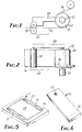
- the cutting step preferably comprises the step illustrated in Figure 3 of (1) transversely cutting the roll 20 along the periphery of the roller 18 at a location between pads to be formed (which can be done manually with a utility knife 26 or by an automated cutter); (2) removing the cut roll 20 from the roller 18 and generally flattening the removed cut roll 20 as illustrated in Figure 4 (which can be done manually); and (4) cutting pads 27 ( Figure 4) from the generally flattened removed cut roll 20 (which can be done with an appropriate die cutting device 28).
- the method according to the present invention can further include the step of adhering a length of liner strip 36 to a portion of each sheet in a pad made by the method along one edge of the sheet by feeding a continuous length of the liner strip 36 onto the periphery of the roller 18 as is ilIustrated in Figures 1 and 2, which can result in the liner strips 36 illustrated in the pads 11 and 14 shown in Figures 3 and 4.
- Such liner strips 36 are typically easily removable from the sheets in the pad 11 or 14, and while present, facilitate separating the edges of sheets in the pad 11 or 14 so that the top sheet in the pad 11 or 14 can easily be removed from the pad 11 or 14.
- Figure 5 illustrates the pad 11 of pressure sensitive adhesive coated sheets with a similar discontinuity on each sheet in the form of the printed indicia 10 with the printed indicia 10 on each sheet in the pad 11 substantially aligned with the printed indicia 10 on adjacent sheets in the pad 11. Because of the slippage of the strip 16 between the printing plates 30 that occurs as the thickness of the roll 20 increases, the discontinuity or printed indicia 10 will increase slightly in size (e.g., typically about 0.01 percent) between adjacent sheets from the bottom most sheet to the topmost sheet in the pad 11.
- the pressure sensitive adhesive coated sheets in the pad 11 are transparent, it is also preferred to print under the printed indicia 10 an opaque background strip 37 of a color that contrasts with the printed indicia 10.
- the background strip 37 facilitates reading the printed indicia on the top sheet in the pad 11 which may be difficult when the background strip 37 is not present due to slight misalignments of the indicia 10 on the stacked sheets in the pad 11, and the background strip 37 masks such slight misalignment to improve the appearance of the pad 11.
- the sheets in the pad 11 each further include a discontinuity in the form of a layer of adhesive masking material 38 in a rectangular pattern located centrally on the adhesive coated surface of the sheet with the printed indicia 10 extending around the masking material 38.
- the sheets of the pad 11 are thus particularly useful as covers for papers (such as shipping papers) attached to containers such as boxes and are essentially the same as the sheets previously provided in roll form, commercially designated No. 824 Pouch Tape and available from Minnesota Mining and Manufacturing Company, St. Paul, Minnesota.
- Figure 6 illustrates the pad 14 of pressure sensitive adhesive coated sheets with a similar discontinuity on each sheet in the form of the opening 13 with the opening 13 on each sheet in the pad 14 substantially aligned with the opening 13 on adjacent sheets. Because of the slippage of the strip 16 through the rotary die 30 that occurs as the thickness of the roll 20 increases, the discontinuity or opening 13 will increase slightly in size by slightly elongating from the bottom most sheet to the topmost sheet in the pad 14.
Landscapes
- Making Paper Articles (AREA)
- Adhesive Tapes (AREA)
- Laminated Bodies (AREA)
- Labeling Devices (AREA)
- Application Of Or Painting With Fluid Materials (AREA)
Claims (9)
- Procédé de façonnage de blocs de feuilles enduites d'un adhésif autocollant, comportant sur chaque feuille une discontinuité semblable sensiblement alignée avec la discontinuité de feuilles adjacentes du bloc, comprenant :
un enroulement en spirale d'une bande (16) de matériau enduit d'un adhésif autocollant autour de la périphérie d'un cylindre (18) pour former un rouleau (20), comprenant une multiplicité de couches superposées de la bande (16), en faisant tourner le cylindre (18) autour de son axe pour tirer la bande (16), le long d'un trajet prédéterminé (22), sur le cylindre (18),
un façonnage de discontinuités sur la bande (16) le long du trajet prédéterminé (22), en des endroits qui sont écartés progressivement de façon croissante pour compenser l'accroissement de circonférence du rouleau (20) et qui aboutit à la disposition d'au moins un ensemble de discontinuités le long de la périphérie du cylindre (18) sensiblement en alignement, radialement vers l'extérieur du cylindre (18), et
une coupe à partir du rouleau (20) d'au moins un bloc contenant au moins un ensemble de discontinuités alignées. - Procédé suivant la revendication 1, dans lequel l'étape de façonnage est caractérisée en outre par :
un agencement d'un mécanisme positionné le long du trajet prédéterminé (22) et comprenant un élément tournant (30) qui présente une périphérie adaptée pour se déplacer dans la direction du mouvement de la bande (16) du matériau enduit d'adhésif autocollant, le long du trajet prédéterminé (22), et pour former la discontinuité en entrant progressivement en contact avec la bande (16) de matériau enduit d'adhésif autocollant, le long d'une zone transversale,
en amenant la longueur périphérique du cylindre (18) à être un multiple pair de la longueur périphérique effective de l'élément tournant (30) et
en commandant l'élément tournant (30) et le cylindre (18) à un rapport de vitesse de rotation fixe qui généralement fait correspondre la vitesse périphérique de l'élément tournant (30) à la vitesse linéaire de la bande (16) le long de la partie de trajet prédéterminé (22) lorsque la première couche de la bande (16) est enroulée autour de la périphérie du cylindre (18), de sorte qu'à mesure que le rouleau (20) autour du cylindre (18) augmente en épaisseur, la bande (16) le long du trajet prédéterminé est tirée à des vitesses linéaires croissantes, le long du trajet prédéterminé (22), qui sont plus rapides que la vitesse périphérique effective de l'élément tournant (30), afin d'écarter progressivement de façon croissante les discontinuités et d'accroître progressivement la longueur des discontinuités successives façonnées par l'élément tournant (30), en alignant par cela des bords des ensembles de discontinuités généralement radialement vers l'extérieur du cylindre (18). - Procédé suivant la revendication 1, dans lequel l'étape de coupe est caractérisée en outre par :
une coupe transversale du rouleau (20) le long de la périphérie du cylindre (18) en un endroit entre des blocs à former,
un retrait du rouleau coupé (20) du cylindre (18),
un aplatissement dans l'ensemble du rouleau coupé retiré (20), et
une coupe des blocs (27) à partir du rouleau coupé (20) retiré et aplati dans l'ensemble. - Procédé suivant la revendication 1, caractérisé en ce qu'il comporte en outre une étape de fixation par adhérence d'une bande de revêtement (36) sur une partie de chaque feuille du bloc, le long d'un bord de la feuille.
- Procédé suivant la revendication 1, caractérisé en outre en ce que l'étape du façonnage d'une discontinuité dans chaque feuille comporte un façonnage d'une ouverture (13) à travers la feuille.
- Procédé suivant la revendication 1, caractérisé en outre en ce que l'étape du façonnage d'une discontinuité dans chaque feuille comporte un façonnage d'indices imprimés (10) sur la feuille.
- Procédé suivant la revendication 6, caractérisé en ce outre en ce que l'étape du façonnage de la discontinuité comporte en outre une application d'une couche d'un matériau de masquage adhésif (38), dans une configuration rectangulaire, situé centralement sur la surface enduite d'adhésif de la feuille, les indices imprimés étant situés autour du matériau de masquage.
- Procédé suivant la revendication 6, caractérisé en outre en ce que les feuilles sont transparentes et en ce que la discontinuité comporte en outre une bande d'arrière-plan opaque (37) d'une couleur qui fait contraste avec les indices imprimés (10), sous les indices imprimés (10) de chaque feuille.
- Procédé suivant la revendication 8, caractérisé en ce que l'étape du façonnage de la discontinuité comporte en outre une application d'une couche d'un matériau de masquage adhésif transparent (38), dans une configuration rectangulaire, situé centralement sur la surface enduite d'adhésif de la feuille, la bande d'arrière-plan (37) et les indices imprimés (10) étant situés autour du matériau de masquage susdit.
Applications Claiming Priority (2)
| Application Number | Priority Date | Filing Date | Title |
|---|---|---|---|
| US07/010,213 US4842919A (en) | 1987-02-03 | 1987-02-03 | Pad forming method |
| US10213 | 1987-02-03 |
Publications (3)
| Publication Number | Publication Date |
|---|---|
| EP0278663A2 EP0278663A2 (fr) | 1988-08-17 |
| EP0278663A3 EP0278663A3 (fr) | 1991-03-27 |
| EP0278663B1 true EP0278663B1 (fr) | 1994-03-23 |
Family
ID=21744553
Family Applications (1)
| Application Number | Title | Priority Date | Filing Date |
|---|---|---|---|
| EP88300881A Expired - Lifetime EP0278663B1 (fr) | 1987-02-03 | 1988-02-02 | Procédé pour former des coussins |
Country Status (11)
| Country | Link |
|---|---|
| US (2) | US4842919A (fr) |
| EP (1) | EP0278663B1 (fr) |
| JP (2) | JPH0755475B2 (fr) |
| KR (1) | KR950011434B1 (fr) |
| AR (1) | AR245405A1 (fr) |
| AU (2) | AU607733B2 (fr) |
| BR (1) | BR8800303A (fr) |
| CA (1) | CA1314574C (fr) |
| DE (1) | DE3888553T2 (fr) |
| ES (1) | ES2050151T3 (fr) |
| ZA (1) | ZA88739B (fr) |
Families Citing this family (39)
| Publication number | Priority date | Publication date | Assignee | Title |
|---|---|---|---|---|
| US5251936A (en) * | 1991-06-05 | 1993-10-12 | Fitzgibbons Gary W | Overlap check construction or similar business form |
| US5199924A (en) * | 1991-06-20 | 1993-04-06 | Uarco Incorporated | Structure for and method of making overlapping multipart business form unit sets |
| US5286546A (en) * | 1991-10-10 | 1994-02-15 | Su Ping Yao | Position marking and easy tearing-off for self-stick removable note pad or similar devices |
| US5484499A (en) * | 1993-12-17 | 1996-01-16 | Converex, Inc. | Method and apparatus for laying up laminates of adhesive backed sheets |
| NL9400424A (nl) * | 1994-03-17 | 1995-11-01 | Jei Lee Corp | Werkwijze en inrichting voor het vervaardigen van vellen voor het inpakken van producten. |
| US5543190A (en) * | 1994-06-16 | 1996-08-06 | Minnesota Mining And Manufacturing Company | Album containing pads of two-side coated repositionable tapes |
| AUPN861896A0 (en) * | 1996-03-13 | 1996-04-04 | Robinson, Alec | Marker for highlighting indicia |
| US5827591A (en) * | 1996-10-08 | 1998-10-27 | Tricor Direct, Inc. | Removable adhesive notes for an industrial setting |
| US6268032B1 (en) * | 1997-10-03 | 2001-07-31 | 3M Innovative Properties Company | Repositionable note sheets and method of formation thereof |
| EP1123016A2 (fr) | 1998-07-01 | 2001-08-16 | Stephanie L. Heroff | Piece de vetement avec soutien-gorge integre |
| US6482488B1 (en) | 1998-10-28 | 2002-11-19 | 3M Innovative Properties Company | Repaired scratched and/or abraded transparent substrates having protective removable sheets thereon and a method of making |
| US6461709B1 (en) * | 1998-10-28 | 2002-10-08 | 3M Innovative Properties Company | Graffiti and/or environmental protective article having removable sheets, substrates protected therewith, and a method of use |
| US6180245B1 (en) | 1998-10-28 | 2001-01-30 | 3M Innovative Properties Company | Method of repairing scratched and/or abraded transparent substrates and the repaired substrates |
| US6536045B1 (en) * | 1999-11-24 | 2003-03-25 | Racing Optics | Tear-off optical stack having peripheral seal mount |
| US6870686B2 (en) * | 1999-11-24 | 2005-03-22 | Bart Wilson | Stack of clear laminated removable lenses for reducing surface drag on airfioils |
| US20020159159A1 (en) * | 1999-11-24 | 2002-10-31 | Bart Wilson | Optical stack of laminated removable lenses |
| US6777055B2 (en) * | 2000-06-27 | 2004-08-17 | 3M Innovative Properties Company | Protective article having removable sheets and vertically staggered side edge, substrates protected therewith, and a method of use |
| US20020192415A1 (en) | 2001-06-15 | 2002-12-19 | 3M Innovative Properties Company | Stack of adhesive articles |
| US7097727B2 (en) * | 2003-05-06 | 2006-08-29 | 3M Innovative Properties Company | Inline accumulating die padder |
| US7818941B2 (en) | 2003-11-24 | 2010-10-26 | Bearacade Products Llc | Plastic sheet barrier enclosure, system, and method |
| US7559159B1 (en) * | 2004-01-09 | 2009-07-14 | Lundberg Gwendolyn E | Solemat |
| US20050183979A1 (en) * | 2004-02-19 | 2005-08-25 | Bart Wilson | Package with removable decals |
| US20080092457A1 (en) * | 2006-03-31 | 2008-04-24 | Marilyn Malone | Articles for Selecting Colors for Surfaces |
| US8528731B2 (en) | 2010-04-21 | 2013-09-10 | Ccl Label, Inc. | Labels, related pads thereof, and related methods |
| USD683397S1 (en) | 2010-04-21 | 2013-05-28 | Avery Dennison Corporation | Pad of labels |
| US20170031525A1 (en) | 2010-05-14 | 2017-02-02 | Racing Optics, Inc. | Touch screen shield |
| US9295297B2 (en) | 2014-06-17 | 2016-03-29 | Racing Optics, Inc. | Adhesive mountable stack of removable layers |
| US10583639B2 (en) | 2014-07-22 | 2020-03-10 | Vampire Optical Coating, Inc. | Multilayer stack of polymer films |
| USD862601S1 (en) | 2016-07-07 | 2019-10-08 | Ccl Label, Inc. | Carrier assembly |
| US11846788B2 (en) | 2019-02-01 | 2023-12-19 | Racing Optics, Inc. | Thermoform windshield stack with integrated formable mold |
| CN113453882B (zh) | 2019-02-01 | 2024-03-15 | 锐思凌光学有限责任公司 | 具有集成可成形模具的热成形挡风玻璃堆叠 |
| US11364715B2 (en) | 2019-05-21 | 2022-06-21 | Racing Optics, Inc. | Polymer safety glazing for vehicles |
| US11648723B2 (en) | 2019-12-03 | 2023-05-16 | Racing Optics, Inc. | Method and apparatus for reducing non-normal incidence distortion in glazing films |
| US11548356B2 (en) | 2020-03-10 | 2023-01-10 | Racing Optics, Inc. | Protective barrier for safety glazing |
| US11490667B1 (en) | 2021-06-08 | 2022-11-08 | Racing Optics, Inc. | Low haze UV blocking removable lens stack |
| US11307329B1 (en) | 2021-07-27 | 2022-04-19 | Racing Optics, Inc. | Low reflectance removable lens stack |
| US11709296B2 (en) | 2021-07-27 | 2023-07-25 | Racing Optics, Inc. | Low reflectance removable lens stack |
| US11933943B2 (en) | 2022-06-06 | 2024-03-19 | Laminated Film Llc | Stack of sterile peelable lenses with low creep |
| US11808952B1 (en) | 2022-09-26 | 2023-11-07 | Racing Optics, Inc. | Low static optical removable lens stack |
Family Cites Families (66)
| Publication number | Priority date | Publication date | Assignee | Title |
|---|---|---|---|---|
| US538464A (en) * | 1895-04-30 | Fabrics | ||
| US1577620A (en) * | 1926-03-23 | Rotary cutter | ||
| US808578A (en) * | 1905-03-24 | 1905-12-26 | Jake B Price | Machine for removing and cutting material from cores. |
| US880465A (en) * | 1905-09-13 | 1908-02-25 | Adolph E Brion | Cutting mechanism for wrapping-machines. |
| US846716A (en) * | 1906-07-19 | 1907-03-12 | Paul Ashelm | Machine for assembling leaves. |
| US1296934A (en) * | 1914-04-21 | 1919-03-11 | Eugene Drouilly | Process for cutting and piling up thin aluminium sheets. |
| US1366082A (en) * | 1918-12-24 | 1921-01-18 | Burgess Battery Co | Recovering components of exhausted dry-battery cells |
| US1643120A (en) * | 1924-07-29 | 1927-09-20 | Firestone Tire & Rubber Co | Rotary cutter |
| US1542082A (en) * | 1925-02-02 | 1925-06-16 | Washburn Crosby Company | Cord winding and cutting device |
| US1880416A (en) * | 1928-02-17 | 1932-10-04 | Tabulating Machine Co | Printing mechanism for accounting machines |
| US1850720A (en) * | 1929-04-05 | 1932-03-22 | Harris Seyboldpotter Company | Slitting and collecting mechanism |
| US2010308A (en) * | 1934-04-19 | 1935-08-06 | Orenda Corp | Apparatus for making ply-board |
| US2066566A (en) * | 1934-05-01 | 1937-01-05 | Janson Einar Henrik | Process of winding and cutting paper into sizes |
| US2105707A (en) * | 1936-07-28 | 1938-01-18 | Louis G Stancliff | Device for winding and cutting cellophane |
| US2208774A (en) * | 1938-11-30 | 1940-07-23 | Ridgely B Pierson | Method of and apparatus for producing measured lengths of cloth |
| US2265498A (en) * | 1939-05-17 | 1941-12-09 | Wagner | Apparatus for winding and cutting web material |
| US2260573A (en) * | 1939-09-09 | 1941-10-28 | Lorch Otto | Process for the production of indicia and like designs |
| US2261967A (en) * | 1940-03-30 | 1941-11-11 | Maxson Automatic Mach | Sheet-feeding method and machine |
| US2258348A (en) * | 1940-08-04 | 1941-10-07 | United Eng Foundry Co | Shear |
| US2341956A (en) * | 1943-07-22 | 1944-02-15 | Edwin G Staude | Patch applying mechanism |
| US2771026A (en) * | 1950-02-06 | 1956-11-20 | Laurence R Mooney | Stencil assembly |
| US2759543A (en) * | 1950-05-26 | 1956-08-21 | American Viscose Corp | Sheeter |
| US2703612A (en) * | 1951-04-25 | 1955-03-08 | Norman H Nye | Apparatus for cutting sheets of plastic film |
| US2725980A (en) * | 1951-12-18 | 1955-12-06 | Cellucord Corp | Stuffer warp ribbon for pile fabric and method of making same |
| US2852074A (en) * | 1953-01-27 | 1958-09-16 | Bradford W J Paper Co | Means for making paper partitions |
| US2804189A (en) * | 1953-07-08 | 1957-08-27 | William F Huck | Machine for severing and trimming paper products and the like |
| US2805828A (en) * | 1954-09-09 | 1957-09-10 | Carl O Bachman | Collapsible reel |
| US2855996A (en) * | 1955-03-16 | 1958-10-14 | Western Printing & Lithographi | Conveyor for flexible sheets |
| US2836018A (en) * | 1956-09-25 | 1958-05-27 | Gen Motors Corp | Manufacturing device |
| CH374885A (de) * | 1958-11-19 | 1964-01-31 | Stempel Ag D | Verfahren und Einrichtung zur Herstellung von zu Wabenmaterial weiterverarbeitbaren Stapeln |
| US2957065A (en) * | 1959-03-30 | 1960-10-18 | American Cyanamid Co | Apparatus for removing waste filamentary material from a spool or bobbin |
| US3163066A (en) * | 1959-10-01 | 1964-12-29 | Kimberly Clark Co | Papermaking machine |
| US3082141A (en) * | 1960-03-07 | 1963-03-19 | Hexcel Products Inc | Method of forming flat sections of honeycomb structure from paper stock |
| US3146649A (en) * | 1960-05-02 | 1964-09-01 | Kimberly Clark Co | Papermaking machine |
| FR1292719A (fr) * | 1961-06-21 | 1962-05-04 | Emballage d'ensembles de clichés empilés | |
| US3160044A (en) * | 1961-07-25 | 1964-12-08 | Gen Electric | Method of cutting wound magnetic cores |
| US3204501A (en) * | 1962-01-22 | 1965-09-07 | United States Steel Corp | Apparatus for cutting coiled metal strip into sheets |
| US3245302A (en) * | 1964-06-01 | 1966-04-12 | Kimberly Clark Co | Apparatus for cutting sheet material from a core |
| GB1145177A (en) * | 1967-01-06 | 1969-03-12 | Swedish Crucible Steel Company | Method and apparatus for producing foam plastic sheet stacks |
| FR2059936B1 (fr) * | 1969-02-13 | 1973-04-06 | Comptoir Europ Distri | |
| US3675525A (en) * | 1970-08-21 | 1972-07-11 | William C Ellison | Machine for cutting rolls of sheet material |
| US3874893A (en) * | 1970-12-17 | 1975-04-01 | Cherrin Abe | Shipping documents device and method |
| AT319820B (de) * | 1971-07-21 | 1975-01-10 | Ritter Kg | Notizblock |
| US3785102A (en) * | 1971-11-01 | 1974-01-15 | Edward T Strickland | Tacky floor pad |
| US3845948A (en) * | 1972-07-17 | 1974-11-05 | Int Paper Co | Method of and apparatus for producing stacks of folded sheet material |
| JPS538337Y2 (fr) * | 1972-09-12 | 1978-03-04 | ||
| US3818587A (en) * | 1972-11-13 | 1974-06-25 | Gen Electric | Method for providing staggered joint, single turn, cut core laminations |
| US3791267A (en) * | 1972-11-27 | 1974-02-12 | Aberdeen Bag Co | Method and apparatus for making packages of interconnected plastic bags and the like |
| US3889892A (en) * | 1973-08-09 | 1975-06-17 | Beloit Corp | Center start surface wind reel with automatic cut-off and transfer |
| US4014535A (en) * | 1975-06-11 | 1977-03-29 | Pitney-Bowes, Inc. | Continuous sheet collating method and apparatus |
| US4107811A (en) * | 1977-04-19 | 1978-08-22 | Arbrook, Inc. | Tacky floor mat with improved peeling provision |
| US4141515A (en) * | 1977-08-02 | 1979-02-27 | Corning Glass Works | Automated layer separator delivery system for optical waveguide winding |
| US4327617A (en) * | 1980-01-30 | 1982-05-04 | Nassau Recycle Corporation | Coil removal apparatus |
| JPS5739934A (en) * | 1980-08-22 | 1982-03-05 | Sekisui Plastics Co Ltd | Rewinding and cutting method for foaming resin sheet and rewinder used for said method |
| US4409870A (en) * | 1980-09-15 | 1983-10-18 | Blava In-Line, Inc. | Apparatus for continuously cutting and removing thin trim strips from a printed web |
| JPS57135149A (en) * | 1981-02-16 | 1982-08-20 | Kaneron Kk | Duster mat and its manufacture |
| JPS57183964A (en) * | 1981-05-07 | 1982-11-12 | Mitsubishi Gas Chemical Co | Package of deoxidizer |
| JPS5878322A (ja) * | 1981-11-05 | 1983-05-11 | 株式会社 南千住製作所 | テ−プパツトの補給装置 |
| US4484501A (en) * | 1982-01-28 | 1984-11-27 | E.C.H. Will (Gmbh & Co.) | Apparatus for cutting and trimming paper sheets or the like |
| JPS5974866A (ja) * | 1982-10-15 | 1984-04-27 | Sumitomo Electric Ind Ltd | テ−ピング装置の回転数制御方法 |
| US4476761A (en) * | 1982-10-21 | 1984-10-16 | Champion International Corporation | Paper roll splitter attachment for fork lift truck |
| GB2163766B (en) * | 1984-08-30 | 1988-01-27 | Kelco Ail Int Ltd | Printing paste thickener compositions |
| JPS61102235A (ja) * | 1984-10-25 | 1986-05-20 | Daio Kakoshi Kogyo Kk | 防塵シ−トの製造方法 |
| US4609208A (en) * | 1985-09-16 | 1986-09-02 | Minnesota Mining And Manufacturing Company | Wire identification label pad |
| US4650706A (en) * | 1986-05-12 | 1987-03-17 | Minnesota Mining And Manufacturing Company | Tabbed tape pad |
| JPH06177949A (ja) * | 1992-12-09 | 1994-06-24 | Fujitsu Ltd | 電話機 |
-
1987
- 1987-02-03 US US07/010,213 patent/US4842919A/en not_active Expired - Lifetime
-
1988
- 1988-01-18 AU AU10363/88A patent/AU607733B2/en not_active Ceased
- 1988-01-19 CA CA000556811A patent/CA1314574C/fr not_active Expired - Fee Related
- 1988-01-27 BR BR8800303A patent/BR8800303A/pt not_active IP Right Cessation
- 1988-01-28 AR AR88309947A patent/AR245405A1/es active
- 1988-02-02 DE DE3888553T patent/DE3888553T2/de not_active Expired - Lifetime
- 1988-02-02 EP EP88300881A patent/EP0278663B1/fr not_active Expired - Lifetime
- 1988-02-02 ES ES88300881T patent/ES2050151T3/es not_active Expired - Lifetime
- 1988-02-02 KR KR1019880000939A patent/KR950011434B1/ko active IP Right Grant
- 1988-02-02 JP JP63021452A patent/JPH0755475B2/ja not_active Expired - Lifetime
- 1988-02-02 ZA ZA88739A patent/ZA88739B/xx unknown
- 1988-11-22 US US07/274,988 patent/US4883553A/en not_active Expired - Lifetime
-
1991
- 1991-01-02 AU AU68620/91A patent/AU632196B2/en not_active Ceased
-
1994
- 1994-01-05 JP JP6000094A patent/JP2502938B2/ja not_active Expired - Lifetime
Also Published As
| Publication number | Publication date |
|---|---|
| BR8800303A (pt) | 1988-09-06 |
| AU607733B2 (en) | 1991-03-14 |
| KR950011434B1 (ko) | 1995-10-04 |
| ZA88739B (en) | 1989-10-25 |
| AU632196B2 (en) | 1992-12-17 |
| AU1036388A (en) | 1988-08-04 |
| JPS63200990A (ja) | 1988-08-19 |
| EP0278663A3 (fr) | 1991-03-27 |
| AU6862091A (en) | 1991-03-14 |
| US4883553A (en) | 1989-11-28 |
| AR245405A1 (es) | 1994-01-31 |
| US4842919A (en) | 1989-06-27 |
| DE3888553T2 (de) | 1994-10-13 |
| JPH0752087A (ja) | 1995-02-28 |
| KR880010174A (ko) | 1988-10-07 |
| JPH0755475B2 (ja) | 1995-06-14 |
| ES2050151T3 (es) | 1994-05-16 |
| DE3888553D1 (de) | 1994-04-28 |
| EP0278663A2 (fr) | 1988-08-17 |
| CA1314574C (fr) | 1993-03-16 |
| JP2502938B2 (ja) | 1996-05-29 |
Similar Documents
| Publication | Publication Date | Title |
|---|---|---|
| EP0278663B1 (fr) | Procédé pour former des coussins | |
| US5700535A (en) | Sheet of labels, method of production and equipment | |
| EP0180365B1 (fr) | Etiquettes et leur fabrication | |
| EP0179575B1 (fr) | Appareil pour la fabrication d'étiquettes | |
| EP0232054B1 (fr) | Etiquettes et leur fabrication | |
| US5486389A (en) | Roll of tape with doubly adhesively faced pads | |
| US4911777A (en) | Method for manufacturing photograph slide sleeving material | |
| US4690720A (en) | Method of manufacturing multilayer labels and apparatus therefor | |
| GB2145362A (en) | Method of, and apparatus for, forming labels | |
| US4405228A (en) | Card negative holder and method of manufacture | |
| US3024155A (en) | Pick-off printed adhesive label and method of making the same | |
| JPH0436933B2 (fr) | ||
| US4475830A (en) | Spliceless ribbon structure having leader and trailer and method of manufacture therefor | |
| US7476191B2 (en) | Die cutting/scoring apparatus sheet material driving member | |
| GB2166109A (en) | Labels | |
| EP0778178B1 (fr) | Production de plaques d'immatriculation pour véhicules | |
| WO1996037427A2 (fr) | Double mecanisme de devidage et d'enroulement a tension separee comprenant un montage a arbre commun | |
| GB2072133A (en) | Machine and method for producing weather-proof multi-leaf shipping forms | |
| EP0386849B1 (fr) | Procédé de fabrication d'étiquettes et étiquette | |
| US4032385A (en) | Method of making an address master card set | |
| US6729374B2 (en) | Label laminating device | |
| US6401782B1 (en) | Label laminating device | |
| EP0075672B1 (fr) | Structure de ruban encreur sans soudure avec ruban d'amorce et son méthode de fabrication | |
| JPH0740476A (ja) | 単位ラベル用紙の作成方法 | |
| JP2585593Y2 (ja) | 帯状ラベル用紙 |
Legal Events
| Date | Code | Title | Description |
|---|---|---|---|
| PUAI | Public reference made under article 153(3) epc to a published international application that has entered the european phase |
Free format text: ORIGINAL CODE: 0009012 |
|
| AK | Designated contracting states |
Kind code of ref document: A2 Designated state(s): BE DE ES FR GB IT NL |
|
| PUAL | Search report despatched |
Free format text: ORIGINAL CODE: 0009013 |
|
| 17P | Request for examination filed |
Effective date: 19910102 |
|
| AK | Designated contracting states |
Kind code of ref document: A3 Designated state(s): BE DE ES FR GB IT NL |
|
| RHK1 | Main classification (correction) |
Ipc: B65H 39/10 |
|
| 17Q | First examination report despatched |
Effective date: 19920715 |
|
| ITF | It: translation for a ep patent filed |
Owner name: BARZANO' E ZANARDO ROMA S.P.A. |
|
| GRAA | (expected) grant |
Free format text: ORIGINAL CODE: 0009210 |
|
| AK | Designated contracting states |
Kind code of ref document: B1 Designated state(s): BE DE ES FR GB IT NL |
|
| REF | Corresponds to: |
Ref document number: 3888553 Country of ref document: DE Date of ref document: 19940428 |
|
| REG | Reference to a national code |
Ref country code: ES Ref legal event code: FG2A Ref document number: 2050151 Country of ref document: ES Kind code of ref document: T3 |
|
| ET | Fr: translation filed | ||
| PGFP | Annual fee paid to national office [announced via postgrant information from national office to epo] |
Ref country code: BE Payment date: 19950125 Year of fee payment: 8 |
|
| PLBE | No opposition filed within time limit |
Free format text: ORIGINAL CODE: 0009261 |
|
| STAA | Information on the status of an ep patent application or granted ep patent |
Free format text: STATUS: NO OPPOSITION FILED WITHIN TIME LIMIT |
|
| PGFP | Annual fee paid to national office [announced via postgrant information from national office to epo] |
Ref country code: ES Payment date: 19950209 Year of fee payment: 8 |
|
| PGFP | Annual fee paid to national office [announced via postgrant information from national office to epo] |
Ref country code: NL Payment date: 19950228 Year of fee payment: 8 |
|
| 26N | No opposition filed | ||
| PG25 | Lapsed in a contracting state [announced via postgrant information from national office to epo] |
Ref country code: ES Free format text: LAPSE BECAUSE OF NON-PAYMENT OF DUE FEES Effective date: 19960203 |
|
| PG25 | Lapsed in a contracting state [announced via postgrant information from national office to epo] |
Ref country code: BE Effective date: 19960228 |
|
| BERE | Be: lapsed |
Owner name: MINNESOTA MINING AND MFG CY Effective date: 19960228 |
|
| PG25 | Lapsed in a contracting state [announced via postgrant information from national office to epo] |
Ref country code: NL Effective date: 19960901 |
|
| NLV4 | Nl: lapsed or anulled due to non-payment of the annual fee |
Effective date: 19960901 |
|
| REG | Reference to a national code |
Ref country code: ES Ref legal event code: FD2A Effective date: 19990503 |
|
| REG | Reference to a national code |
Ref country code: GB Ref legal event code: IF02 |
|
| PGFP | Annual fee paid to national office [announced via postgrant information from national office to epo] |
Ref country code: GB Payment date: 20070223 Year of fee payment: 20 |
|
| PGFP | Annual fee paid to national office [announced via postgrant information from national office to epo] |
Ref country code: DE Payment date: 20070330 Year of fee payment: 20 |
|
| PGFP | Annual fee paid to national office [announced via postgrant information from national office to epo] |
Ref country code: IT Payment date: 20070523 Year of fee payment: 20 |
|
| REG | Reference to a national code |
Ref country code: GB Ref legal event code: PE20 |
|
| PGFP | Annual fee paid to national office [announced via postgrant information from national office to epo] |
Ref country code: FR Payment date: 20070221 Year of fee payment: 20 |
|
| PG25 | Lapsed in a contracting state [announced via postgrant information from national office to epo] |
Ref country code: GB Free format text: LAPSE BECAUSE OF EXPIRATION OF PROTECTION Effective date: 20080201 |