EP0180365B1 - Etiquettes et leur fabrication - Google Patents
Etiquettes et leur fabrication Download PDFInfo
- Publication number
- EP0180365B1 EP0180365B1 EP85307353A EP85307353A EP0180365B1 EP 0180365 B1 EP0180365 B1 EP 0180365B1 EP 85307353 A EP85307353 A EP 85307353A EP 85307353 A EP85307353 A EP 85307353A EP 0180365 B1 EP0180365 B1 EP 0180365B1
- Authority
- EP
- European Patent Office
- Prior art keywords
- self
- front cover
- cut
- folded
- support web
- Prior art date
- Legal status (The legal status is an assumption and is not a legal conclusion. Google has not performed a legal analysis and makes no representation as to the accuracy of the status listed.)
- Expired - Lifetime
Links
Images


Classifications
-
- B—PERFORMING OPERATIONS; TRANSPORTING
- B31—MAKING ARTICLES OF PAPER, CARDBOARD OR MATERIAL WORKED IN A MANNER ANALOGOUS TO PAPER; WORKING PAPER, CARDBOARD OR MATERIAL WORKED IN A MANNER ANALOGOUS TO PAPER
- B31D—MAKING ARTICLES OF PAPER, CARDBOARD OR MATERIAL WORKED IN A MANNER ANALOGOUS TO PAPER, NOT PROVIDED FOR IN SUBCLASSES B31B OR B31C
- B31D1/00—Multiple-step processes for making flat articles ; Making flat articles
- B31D1/02—Multiple-step processes for making flat articles ; Making flat articles the articles being labels or tags
- B31D1/021—Making adhesive labels having a multilayered structure, e.g. provided on carrier webs
-
- G—PHYSICS
- G09—EDUCATION; CRYPTOGRAPHY; DISPLAY; ADVERTISING; SEALS
- G09F—DISPLAYING; ADVERTISING; SIGNS; LABELS OR NAME-PLATES; SEALS
- G09F3/00—Labels, tag tickets, or similar identification or indication means; Seals; Postage or like stamps
- G09F3/02—Forms or constructions
- G09F3/0288—Labels or tickets consisting of more than one part, e.g. with address of sender or other reference on separate section to main label; Multi-copy labels
- G09F3/0289—Pull- or fold-out labels
-
- Y—GENERAL TAGGING OF NEW TECHNOLOGICAL DEVELOPMENTS; GENERAL TAGGING OF CROSS-SECTIONAL TECHNOLOGIES SPANNING OVER SEVERAL SECTIONS OF THE IPC; TECHNICAL SUBJECTS COVERED BY FORMER USPC CROSS-REFERENCE ART COLLECTIONS [XRACs] AND DIGESTS
- Y10—TECHNICAL SUBJECTS COVERED BY FORMER USPC
- Y10T—TECHNICAL SUBJECTS COVERED BY FORMER US CLASSIFICATION
- Y10T156/00—Adhesive bonding and miscellaneous chemical manufacture
- Y10T156/10—Methods of surface bonding and/or assembly therefor
- Y10T156/1052—Methods of surface bonding and/or assembly therefor with cutting, punching, tearing or severing
- Y10T156/108—Flash, trim or excess removal
-
- Y—GENERAL TAGGING OF NEW TECHNOLOGICAL DEVELOPMENTS; GENERAL TAGGING OF CROSS-SECTIONAL TECHNOLOGIES SPANNING OVER SEVERAL SECTIONS OF THE IPC; TECHNICAL SUBJECTS COVERED BY FORMER USPC CROSS-REFERENCE ART COLLECTIONS [XRACs] AND DIGESTS
- Y10—TECHNICAL SUBJECTS COVERED BY FORMER USPC
- Y10T—TECHNICAL SUBJECTS COVERED BY FORMER US CLASSIFICATION
- Y10T156/00—Adhesive bonding and miscellaneous chemical manufacture
- Y10T156/10—Methods of surface bonding and/or assembly therefor
- Y10T156/1089—Methods of surface bonding and/or assembly therefor of discrete laminae to single face of additional lamina
- Y10T156/1092—All laminae planar and face to face
- Y10T156/1093—All laminae planar and face to face with covering of discrete laminae with additional lamina
-
- Y—GENERAL TAGGING OF NEW TECHNOLOGICAL DEVELOPMENTS; GENERAL TAGGING OF CROSS-SECTIONAL TECHNOLOGIES SPANNING OVER SEVERAL SECTIONS OF THE IPC; TECHNICAL SUBJECTS COVERED BY FORMER USPC CROSS-REFERENCE ART COLLECTIONS [XRACs] AND DIGESTS
- Y10—TECHNICAL SUBJECTS COVERED BY FORMER USPC
- Y10T—TECHNICAL SUBJECTS COVERED BY FORMER US CLASSIFICATION
- Y10T428/00—Stock material or miscellaneous articles
- Y10T428/14—Layer or component removable to expose adhesive
Definitions
- the present invention relates to labels, in particular, labels intended to be attached to containers such as boxes, packets, bottles or tins, and to a method of producing a succession of self-adhesive labels carried on a backing of release material.
- EP-A-0 087 987 discloses a so-called "extended text" label for application to containers as claimed in the preamble of claim 1.
- GB-A-2 127 378 discloses a method of producing labels as claimed in steps a-d and f of claim 7.
- the present invention provides a label for affixing to a container comprising a longitudinal strip divided into a series of panels by a plurality of transverse fold lines, the first two panels forming a front cover and a back cover respectively for enveloping the remaining panel or panels of the strip when folded, the transverse fold lines being spaced along the strip so that upon folding of the strip the said remaining panel or panels is or are folded to lie over the back cover and is or are in turn covered by folding of the front cover about the fold line between the front and back covers; a support web to which the said back cover is adhered, the support web being dimensioned so that at least one region thereof extends laterally at least beyond the edge of the back cover which occurs at the fold line between the back cover and the remaining panel or panels; and a layer of pressure-sensitive self-adhesive material which is adhered by the self-adhesive surface thereof over some or all of the front cover panel, the self-adhesive material extending at least beyond the free outer edge of the front cover panel
- the self-adhesive material extends beyond the said at least one region so that the self-adhesive material is also adhered to a part of the support web which is adjacent to or spaced from said at least one region and an elongate cut or weakened tear line through the self-adhesive material separates the said at least one portion from the remainder of the self-adhesive material which is adhered to the said part of the support web.
- the cut or weakened tear line extends generally along the free outer edge of the front cover panel except at at least one place at which the cut or weakened tear line extends laterally away from the free outer edge to form the said at least one portion of self-adhesive material.
- the front cover panel may be dimensioned so that the free outer edge extends beyond the area of the support web occupied by the back cover thereby to form an overlapping portion, the overlapping portion being provided with at least one cut-out which exposes the self adhesive surface of the self-adhesive material so as to form the said at least one portion of self-adhesive material.
- the or each cut-out extends inwardly from the free outer edge to a distance which is greater than the width of the overlapping portion so that the or each portion of self-adhesive material can be adhered both to the support web and to the upper surface of the remaining panel or panels which are exposed by the or each cut-out.
- the free outer edge of the front cover panel is, apart from the cut outs, a straight line and the cut or weakened tear line is a straight line which is coincident with the straight line of the free outer edge.
- the free outer edge of the front cover panel is a straight line and the cut or weakened tear line is substantially a straight line except at the said at least one place.
- the front cover panel is dimensioned so that the free outer edge extends beyond the area of the support web occupied by the back cover thereby to form an overlapping portion, the overlapping portion being provided with two or more cut-out holes which are spaced from and generally along the free outer edge of the front cover panel, each cut-out hole exposing the self-adhesive material so as to form two or more of the said portions of self-adhesive material.
- each cut-out hole is positioned in the front cover panel such that when the front cover panel is folded over the remaining panel or panels each portion of self-adhesive material can be adhered both to the support web and to the upper surface of the remaining panel or panels which are exposed by the respective cut-out holes.
- the label desirably comprises a band of the material of the longitudinal strip which is disposed along the free outer edge of the front cover panel when the front cover panel is folded as aforesaid, the band being separated from the front cover panel by the cut or weakened tear line and being adhered to the support web by the remainder of the self-adhesive material which is adhered to the support web.
- the present invention further provides a method of producing a succession of self-adhesive labels carried on a backing of release material, the method comprising the steps of:-
- the cut or weakened tear line extends generally along the free outer edge of the front cover panel, the free outer edge being opposite the fold line between the front and back cover panels, except at at least one place at which the cut or weakened tear line extends laterally away from the free outer edge to form the said at least one portion of self-adhesive material.
- the front cover panel is dimensioned so that the free outer edge extends beyond the area of the back cover thereby to form an overlapping portion, the overlapping portion being provided with at least one cut-out which exposes the self-adhesive surface of the self-adhesive material so as to form the said at least one portion of the self-adhesive material.
- the free outer edge of the front cover panel is, apart from the cut-out or cut-outs, a straight line and the cut or weakened tear line is a straight line which is coincident with the straight line of the free outer edge.
- the free outer edge of the front cover panel is a straight line and the cut or weakened tear line is substantially a straight line except at the said at least one place.
- the front cover panel is dimensioned so that the free outer edge of the front cover panel, the free outer edge being opposite the fold line between the front and back cover panels, extends beyond the area of the support web occupied by the back cover thereby to form an overlapping portion, the overlapping portion being provided with two or more cut-out holes which are spaced from and generally along the free outer edge of the front cover panel, each cut-out hole exposing the self-adhesive surface of the self-adhesive material so as to form two or more of the said portions of self-adhesive material.
- each cut-out hole is positioned in the front cover panel such that when the front cover panel is folded over the remaining panel or panels each portion of self-adhesive material can be adhered both to the support web and to the upper surface of the remaining panel or panels which are exposed by the respective cut-out holes.
- the cut or weakened tear line is also cut through the longitudinal strip to form a band of the material of the longitudinal strip which is disposed along the free outer edge of the front cover panel when the front cover panel is folded over the remaining panel or panels, the band being separated from the front cover panel by the cut or weakened tear line and being adhered to the support web by the self-adhesive material.
- cutting steps (f) and (g) are carried out simultaneously by a die-cutter.
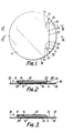
- a label in accordance with the invention is made from a longitudinal strip 2 of paper which divided by transverse folded lines 4, 6, 8 into four panels 10, 12, 14, 16.
- the transverse fold lines, 4, 6, 8 need not exist prior to the folding operations used to form the label during its manufacture.
- the upper surface (in Figures 4 and 5) of each of the panels 10, 12, 14, 16 may carry printed information, as can the lowest surface of each of the panels 10, 14 and 16.
- the lower (or rear) surface of panel 12 is adhered to a support web 18 by a layer of adhesive 20.
- the upper surface of the support web 18 also carries information on those portions thereof which are not covered by the folded strip 2.
- the support web 18 may also have an adhesive on its underside suitable for adhering support web 18 together with its associated strip 2 of panels to a container.
- the adhesive on the underside of the support web 18 is a pressure-sensitive adhesive which is protected by a release backing material (not shown).
- panel 16 is folded about fold line 8 to lie over panel 14. Then panels 14 and 16 are folded about fold line 6 to lie over panel 12. Panel 12 acts as a back cover for the folded label. Thereafter, panel is folded about fold line 4 to lie over panels 14 and 16 and thereby to act as a front cover for the folded label.
- the fold lines 4, 6, 8 are spaced from one another in such a manner that panels 14 and 16 after folding are both contained within the front and back cover panels 10 and 12.
- the width of the front cover panel 10 is greater than the width of back cover panel 12 such that the front cover panel 10 has an overlapping portion 22 which in the folded condition extends beyond the right-hand edge of the folded panels 14 and 16, which edge is defined by the fold line 6, and the right-hand edge of the back cover panel 12.
- Two cut-outs 24, 26 are provided in the front cover panel 10 at the free outer edge 28 thereof which is opposite to the fold line 4 between the front cover panel 10 and the back cover panel 12.
- the cut-outs 24, 26 are semi-circular but may, alternatively, be any desired shape.
- the cut-outs 24, 26 extend inwardly of the panel 10 towards the fold line 4 to a distance which is greater than the width of the overlapping portion 22.
- the cut-outs 24, 26 each expose a surface portion both of the support web 18 and of the folded panel 14, when panel 14 is above panel 16 when the label is folded.
- a layer of a see-through, preferably transparent, plastics material 30 covers the folded strip 2 and the front surface of the support web 18 which is not covered by the folded strip 2.
- the plastics material 30 is self-adhesive and has a coating of a pressure-sensitive adhesive on the underside thereof via which adhesive the plastics material 30 is adhered to the exposed upper surface of the folded strip 2/support web 18 combination.
- the plastics material 30 is an acetate or a polyester film.
- any information which is printed on the front surface of the front cover panel 10 and on the surrounding surfaces of the support web 18 can be seen by a user through the see-through plastics material.
- the layer of plastics material 30 may be opaque and, if desired, itself be printed with information.
- a pressure-sensitive self-adhesive paper may be employed in the labels of the invention.
- the layer of plastics material 30 completely covers the front surface of the label. However, if desired the layer of plastics material 30 may cover only a part of the front surface of the label, provided that the layer of plastics material 30 can adhere the front cover panel 10 to the support web 18 and thereby maintain the folded label in a closed condition.
- the layer of plastics material 30 covers and is adhered by its layer of presure-sensitive adhesive to the surface of the front cover panel 10 and to the front surface of the support web 18 at the side of the folded strip 2.
- the layer of plastics material 30 is also adhered, due to the presence of cut-outs 24, 26 which expose the self-adhesive surface of the layer of plastics material 30 in those regions, to those surface portions of the folded panel 14 and of the support web 18 which are underneath the cut-outs 24, 26 when the label is folded.
- a cut 32 through the thickness of the layer of plastics material 30 extends generally along the free outer edge 28 of the front cover panel 10.
- the cut 32 is formed as a straight line and so does not coincide with the edges of the cut-outs 24, 26 thereby to provide two tabs 34, 36 of plastics material 30 which are located in the registry with the cut-outs 24, 26.
- the cut 32 is shown in Figure 1 as slightly spaced from the free outer edge 28, whereas in the actual embodiment the cut 32 extends along each portion of the free outer edge 28 which is straight.
- the two tabs 34, 36 act so as to adhere the front cover panel 10 to the support web 18 and to the folded panel 14, and thereby to retain the folded label in a closed condition.
- the two adhered tabs 34, 36 are pulled away from the support web 18 and the folded panel 14 so as to release the front cover panel 10 and allow the label to be opened, to a position such as that shown in Figures 4 and 5, where the printed information on the inner surfaces of the panels can be read by a user.
- the folded panels 14, 16 are folded over back cover panel 12 and then front cover panel 10 is folded over the folded panels 14, 16.
- the front cover panel 10 is re-adhered via tabs 34, 36 of plastics material 30 to the support web 18 and to the folded panel 14.
- the pressure-sensitive adhesive which is coated on plastics material 30 is preferably of such a composition so as to allow the front of the panel 10 to be successfully detached from and re-attached to the support web 18 and to the folded panel 14 so that a user can repeatedly open and close the folded label.
- the cut-outs 24, 26 may be dimensioned so that they extend inwardly of the front cover panel 10 to a distance which is less than the width of the overlapping portion 22. In that arrangement, when the folded label is closed the tabs 34, 36 of the plastics material 30 are adhered only to the support web 18 and are not adhered to the folded label 14.
- each label consists of rectangular support web 18 to which is adhered a rectangular folded strip of paper 2.
- the back surface of each support web 18 is coated with a pressure-sensitive adhesive so that each label is self-adhesive and is releasably carried on the release backing material 37.
- the strip 2 is folded in a manner similar to that in the embodiment of Figures 1 to 5 and the back cover panel 12 of the strip is adhered by a layer of adhesive 20 to the front surface of the support web 18.
- the layer of 30 of plastics material covers the label and adheres the front cover panel 10 to the support web 18.
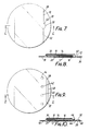
- the front cover panel 10 is provided with only one cut-out 24 at its free outer edge 28 and the cut 32 extends in a straight line along the free outer edge 28 so as to result in a single tab 34 of plastics material 30 which adheres the front cover panel 10 to the support web 18 and maintains the label in a folded condition.
- the labels shown in Figure 6 differ from those shown in Figure 1 to 5 in that in the former labels only one tab 34 of plastics material 30 is present in the label and also the labels are rectangular, rather than circular, in shape.
- the width of the overlapping portion 22 of the front cover of panel 10 is greater than the depth of the cut-out 24 such that when the label is folded, the cut-out 24 exposes only a portion of the support web 18 and not a portion of the folded panel 14, as is the case in the embodiment of Figures 1 to 5.
- the tab 34 of plastics material 30 is adhered only to the support web 18 and not to the folded panel 14.
- the front cover panel 10 is not provided with cut-outs.
- the cut 32 through the plastics material 30 is not a straight line all along its length, as in the embodiment illustrated in Figures 1 to 5.
- the cut 32 is, however, formed as a line of which a major portion is a straight line extending along the free outer edge 28 of the front cover panel 10 and which is provided with a laterallly extending portion 38 which extends away from the free outer edge 28 of the front cover panel 10.
- the laterally extending portion 38 defines a tab 40 of plastics material 30 by which the front cover panel 10 is adhered to the support web 18.
- the folded label may be repeatedly opened and closed by detaching and re- attaching the tab 40 from and to the support web 18.
- the tab 40 is semi-circular but it may be made any particular desired shape.
- FIG. 9 and 10 A further embodiment of the label of the present invention is shown in Figures 9 and 10.
- cut outs 42 are not at the free outer edge 28 of the front cover panel 10 but the cut-outs 42 are punched holes which are situated inwardly of the free outer edge 28 rather than extend inwardly of the free outer edge 28 as in the embodiments of Figures 1 to 5 and Figure 6.
- four circular cut-outs 42 are formed as holes in a line which is parallel to and spaced from the free outer edge 28.
- the cut-outs 42 are formed by punching or by any other suitable manner.
- the cut-outs 42 are dimensioned so that when the front cover panel 10 is folded over the remainder of the folded strip, each cut-out 42 reveals an upper portion of the folded panel 14 and also a portion 44 of the support web 18.
- the layer of plastics material 30 covers the label so that in registry with each cut-out 42 there is a tab portion 46 of the layer of plastics material 30 which is exposed by the respective cut-out 42.
- each exposed tab portion 46 of the plastics material 30 is adhered by its self-adhesive surface to the respective revealed portion of folded panel 14 and portion 44 of the support web 18.
- Cut 32 is formed as a straight line. However, unlike the previous embodiments the cut 32 passes not only through the layer of plastics material 30 but also the front cover panel 10. Thus cut 32 defines a strip 48 of the edge of front cover panel 10 which is adhered by the layer of plastics material 30 to the support web 18 and is adjacent the foldable part of the front cover panel 10.
- the foldable part of the front cover panel 10 may be pulled open by pulling free outer edge 28 away from the support web 18.
- the tab portions 46 are released from the folded panel 14 and the portions 44 of the support web 18.
- the label may be refolded and the tab portions 46 re-adhered by their self-adhesive surface to the folded panel 14 and the portions 44 of the support web 18.
- a major advantage of this embodiment of the invention is that by cutting the cut 32 through both the plastics material and front cover panel 10 in a single step the cut edges of the front cover panel 10 and of the plastics material 30 are automatically in registry.
- the cut 32 is only cut through the plastics material 30 and consequently during the cutting step the cut 32 must be aligned with the free-outer edge 28 of the front cover panel 10, which alignment is often difficult to achieve in a high output automatic production method.
- the cut-outs 42 permit the front cover panel 10 to be conveniently and satisfactorily adhered along the length of free outer edge 28 to both folded panel 14 and to the support web 18. In this way the front cover panel 10 is firmly adhered to and may readily be re-adhered to the folded panel 14 and to the support web 18.
- the cut-outs 42 may be positioned in the front cover panel 10 such that when the label is folded the tab portions 46 are adhered only to the portions 44 of the support web 18 and not to the folded panel 14.
- tabs 34, 36 or 40 or tab portions 46 may be provided in the labels of the present invention, and that those tab or tab portions may be any appropriate desired shape.
- the cut 32 may alternatively be a weakened tear-line, such as, for example, a line of perforations, which is torn when the label is first opened.
- the cut 32 may be spaced from the free outer edge 28 of the front cover panel 10 so as to provide an elongate band of plastics material 30 which can, in addition to the tab or tabs, adhere the front cover panel 10 to the support web 18.
- the circular labels of the preferred embodiments have particular application in the labelling of containers which are circular pots or cans having a removable lid, such as paint pots.
- the labels are dimensioned so that they can be adhered to and fit within the edge of the removable lid.
- the provision of the layer of plastics material helps to protect the label from accidental damage by tearing or soiling, particularly when the pots are stacked one upon another.
- the layer of plastics material is see-through and allows information which is printed on the front surface of the label to be seen by a user.
- the front surface of the folded label may have instructions on how to open the folded label.
- the surface of the panels of the folded strip, which are revealed when the label is unfolded in the manner described hereinabove, may be printed with information regarding the use of the product in the container or relating to the marketing or promotion of the product.
- FIG. 11 there is shown an apparatus, designated generally as 52, for preparing a reel 54 carrying a succession of self-adhesive labels 56 in accordance with the invention.
- the reel 54 of labels is produced starting from a reel 58 of a laminar material 60 commonly known in the art as self-adhesive stock or pressure-sensitive stock.
- a laminar material 60 commonly known in the art as self-adhesive stock or pressure-sensitive stock.
- Such laminar material usually consists of a support web of paper of indeterminate length coated on its reverse side with a layer of pressure-sensitive adhesive, with the adhesive side of the paper being protected with a backing layer 61 of a release material such as silicone-faced backing paper.
- the upper surface of the web of paper is printed along its length with a succession of images, each of which is to constitute the front surface of a respective resultant label 56.
- the web of paper may not be so printed; such an arrangement is employed when the front surface of the resultant self-adhesive labels 56 is to be composed only of the front surface of the folded longitudinal strip 72 which is adhered to the web of paper in the manner which is described hereinbelow.
- the folded longitudinal strip 72 is similar to those which are employed in the embodiments of Figures 1 to 5, Figure 6 or Figures 7 and 8 or Figures 9 and 10.
- the laminar material 60 is unwound from the reel 58 and guided by appropriate guide rollers (not shown) to a folded longitudinal strip applying station 62 and passes, in turn, a "START” sensor 64, a "STOP” sensor 66 and an adhesive-applying station 68 including an adhesive applicator 70.
- START sensor 64 includes a photodetector which scans the laminar material 60 as its passes thereunder.
- the photodetector in the START sensor 64 is arranged to detect a mark which is printed at a succession of particular positions along the length of the laminar material 60.
- an electrical signal is sent therefrom to initiate the operation of the adhesive applicator 70, either immediately or after a predetermined delay of time.
- the adhesive applicator 70 deposits a layer of adhesive across a particular portion of the width of the laminar material 60.
- the adhesive may be any suitable adhesive for paper, such as, for example, PVA (poly vinyl alcohol) adhesive.
- the adhesive is applied to a part of the laminar material 60 which is downstream along the laminar material 60 from that part of the laminar material 60 which was detected by the START sensor 64.
- STOP sensor 66 also includes a photodetector which is similar in operation and construction to that included in START sensor 64.
- the photodetector in STOP sensor 66 detects the same or a different mark on the laminar material 60 as the photodetector in START sensor 64.
- an electrical signal is sent therefrom to terminate the operation of the adhesive applicator 70, either immediately or after a predetermined delay of time.
- the laminar material 60 has applied thereto a succession of layers of adhesive of predetermined dimensions.
- the laminar material 60 is then conveyed to the label applying station 62.
- the START and STOP sensors 64, 66 detect the same mark the START sensor 64 and the STOP sensor 66 are separated, along the direction of travel of the laminar material 60, by a distance which is equal to the length of each layer of adhesive.
- Adhesive applicator 70 may include an applicator head which is elongate and extends transverse the direction of movement of the web. A row of holes is provided along the length of the applicator head. When adhesive is to be applied to the laminar material 60, adhesive is expressed through the holes for a given period on to the upper surface of the moving laminar material 60. This causes a plurality of elongate beads of adhesive of given length to be formed along the length of, and across a desired portion of the width of, the laminar material 60.
- the expressing of the adhesive through the holes may be made intermittent and, in addition, the particular holes through which the adhesive is expressed may be varied for any cycle of adhesive application.
- the resultant dots of adhesive are deposited on to the laminar material in a manner similar to dot-matrix printing whereby a desired pattern of dots of adhesive is applied to the laminar material 60.
- a plurality of the folded longitudinal strips 72 similar to those shown in the preceding figures are held as a stack thereof in a magazine 74.
- Each folded longitudinal strip 72 is pre-printed as desired and is already formed with the appropriate cut-outs, the type of cut-outs depending on which embodiment of the invention is being made.
- the front cover panel 10 of the folded strips is the uppermost of the panels of each folded strip so that each folded strip is ready for application to the support web.
- the bottom of the magazine 74 includes an opening 76 in the bottom wall 78 which extends as far as one of the side walls 80 of the magazine 74.
- a rotatable cylinder 82 which is hollow and has a plurality of holes provided in the cylindrical wall of the cylinder 82, which holes pass through the thickness of the cylindrical wall, is mounted beneath the opening 76 with the axis of the cylinder being perpendicular to the stack of folded longitudinal strips 72.
- the cylinder 82 extends into the opening 76 so that the bottom folded strip 72 in the stack rests against the uppermost surface portion of the cylinder 82.
- a vacuum is continuously maintained in the cylinder 82 by evacuating means (not shown), e.g. a vacuum pump, so that the folded strip 72 which is at the bottom of the stack has the back cover panel 12 thereof which is adjacent the cylinder 82 sucked by the vacuum against the upper surface of the cylinder 82.
- the strength of the vacuum is such as substantially not to deform the bottom folded strip 72 but so as to ensure that the bottom folded strip 72 can be moved, by rotation of the cylinder 82 by a rotary drove means 84, out of the opening 76 in the magazine 74 against the friction between the said folded strip 72 and the next-to-bottom folded strip 72.
- the cylinder 82 is rotated intermittently in order successively to feed out folded strips 72 from the stack in the magazine 74.
- the rotary drive means 84 is preferably an electric motor which drives the cylinder 82 either via a belt or directly.
- the folded strips 72 which are fed out from the magazine 74 by the rotation of the vacuum cylinder 82 are deposited onto and travel along the upper surface of a plate 86.
- the folded strips 72 are conveyed along the plate 86 by means of a rotatable endless belt 88 which is mounted on two spaced rollers 89 and which is driven by a drive means 90 which drives one of the rollers 89.
- the drive means 90 is an electric motor which drives the roller 89 either via a belt or directly.
- the endless belt 88 extends along the length of the plate 86 with the bottom surface of the endless belt 88 being located parallel to and slightly above the upper surface of the plate 86 so that each folded strip 72 is held firmly between plate 86 and endless belt 88 as it moves along the plate 86.
- the endless belt 88 may be made of any suitable material such as, for example, rubber.
- the endless belt 48 is rotated in an anti-clockwise direction in the apparatus of Figure 11.
- the endless belt 88 is rotated intermittently and in synchronism with the rotation of the vacuum cylinder 82, so that when a folded strip 72 is fed out from the magazine 74 by the rotation of the vacuum cylinder 82, the rotating endless belt 88 engages the top surface of the folded strip 72 and urges the folded strip 72 along the plate 86.
- the duration of the rotation cycle of the vacuum cylinder 82 and the endless belt 48 can be such so as to provide along the plate 86 a succession of folded strips 72 in abutting relationship. Alternatively, the duration of the rotation cycle by be such so as to have the succession of folded strips 72 in overlapping relationship.
- the ram 92 consists of one or more rollers. More preferably, the ram 92 consists of one or more rollers which are driven when the ram 92 pushes the folded strips 72 as aforesaid, the speed of rotation of the surface of the rollers being the same as the surface speed of movement of the web.
- the folded strip applying station 62 includes control means for controlling the operation of the rotary drive means 84 for the vacuum cylinder 82; control means for controlling the operation of the drive means 90 for the endless belt 88; and the ram 92, and is situated at the downstream end of the plate 86.
- the label applying station 62 includes a label detector which is a photodetector 96 which is situated at, and directed towards the upper surface of, the downstream end of plate 86. The photodetector 96 detects whether or not a folded strip 72 is underneath the photodetector 96 at the downstream end of the plate 86 by sensing the amount of light reflected into the photodector 96 from the plate 86 or from a folded strip 72.
- the photodetector 96 When a folded strip 72 is under the photodetector 96 the amount of light reflected from the folded strip 72 into the photodetector 96 is different from that reflected from the plate 86 when a folded strip 72 is not under the photodetector 96.
- the photodetector 96 detects that a folded strip 72 is not under the photodetector 96 at the end of the plate 86, the photodetector 96 emits an electrical signal which switches ON the rotary drive means 84 for the vacuum cylinder 82 and drive means 90 for the endless belt 88.
- folded strips 72 are fed along the plate 86 from the magazine 74 towards the the photodetector 96.
- the leading folded strip 72 passes along the plate 86 under the photodetector 96 and then under the ram 92.
- the leading edge of the leading folded strip 72 then contacts a front-edge detector 98 which is situated downstream of the ram 92 and extends across the pathway of the folded strips 72.
- the front-edge detector 98 acts as a switch when the front-edge of the leading folded strip 72 contacts the front-edge detector 98. When so contacted, the front-edge detector 98 switches OFF the rotary drive means 84 for the vacuum cylinder 82 and the drive means 90 for the endless belt 88.
- the front edge detector 98 also sends an electrical signal to the ram 92 which signal is an ENABLE signal for enabling the ram 92 to operate. The ENABLE signal does not initiate the operation of the ram 92 but rather allows the ram 92 to operate.
- the operation of the ram 92 is initiated by an electrical signal which is sent to the ram 92 from START sensor 64.
- the START sensor 64 sends the signal to the ram 92 when the START sensor 64 initiates the operation of the adhesive applicator 70, either immediately or after a predetermined delay of time.
- ram 92 moves downwardly towards and against the upper surface of the leading folded strip 72 so as to push the leading folded strip 72 towards the moving laminar material 60.
- the arrangement is such that the leading edge of the leading folded strip 72 is pushed by the ram 92 onto a respective adhesive layer on laminar material 60.
- the ram 92 continues to act on the leading folded strip 72 and the leading folded strip 72 is carried away from the ram 92 by the moving adhesive layer.
- the translational movement of the leading folded strip 72 as it is carried away along the web causes rotation of the one or more rollers.
- the provision of one or more rollers tends to minimise the frictional resistance acting on the leading folded strips 72 as it moves away from the label applying station 62.
- the one or more rollers are driven, the one or more rollers help to overcome the frictional resistance and drive the leading folding strip 72 onto the adhesive layer on the moving web.
- the ram 92 pushes the leading folded strip 72 beneath the level of the bottom of the front-edge detector 98 so that the adhered folded strip 72 can pass beneath the front-edge detector 98.
- the ram 92 is arranged to operate when the leading edge of the leading folded strip 72 substantially coincides with the leading edge of the respective layer of adhesive on the laminar material 60.
- the length of each layer of adhesive substantially corresponds to the length of the back cover of the folded strip 72.
- the photodetector 96 senses that there is no folded strip 72 at the end of plate 86 and so initiates the operation of the vacuum cylinder 82 and the endless belt 88 to deliver another folded strip 72 from the magazine 74 onto the upstream end of plate 86 and the new leading folded strip 72 on the plate 86 to the label applying station 62.
- operation of the ram is initiated as described hereinabove so that the next folded strip 72 is adhered to the next layer of adhesive.
- the laminar material 60 with the succession of folded strips 72 applied thereto is then fed to a self-adhesive material applying station 100 which includes a pair of nip rollers 102.
- a self-adhesive material applying station 100 which includes a pair of nip rollers 102.
- an elongate web of a pressure-sensitive self-adhesive material 104 such as a polyester or acetate plastics film having a coating of a pressure-sensitive adhesive, is fed from a reel 106 thereof to the nip rollers 102.
- the nip rollers 102 press the self-adhesive surface of the self-adhesive material 104 against the upper surface of the laminar material 60 and of the folded strips 72, so that the self-adhesive material 104 is adhered thereto.
- the combination of the laminar material 60 with the succession of folded strips 72 applied thereto and the layer of self-adhesive material 104 is then fed to die-cutting station 108 which includes a die-cutting roller 110 coupled with a backing roller 112.
- the die-cutting roller 110 cuts through the self-adhesive material 104, the support web of paper and the folded strips 72 as far as the backing layer 61.
- the backing layer 61 is not cut by the die-cutting roller, thereby to provide a succession of spaced individual composite labels 56 on the backing layer 61, which is then wound up onto a reel 54.
- the waste web remnant 114 consisting of portions of the self-adhesive material 104, the web and the folded strips 72 outside the edge of the composite labels 56 is removed from the backing layer 61 and wound up on a roll 116.
- the die-cutting roller 110 also cuts the cut 32 through the layer of self-adhesive material 104 so as to form the tab or tabs of self-adhesive material which releasably adhere the front cover panel 10 of the folded strips 72 to the support web 18.
- the die-cutting roller also cuts the cut 32 through the layer of plastics material 104 and the front cover panel 10 so that the front cover panel 10 is releasbly adhered to the folded panel 14 and to the support web by the tab portions 46.
- the cut 32 may be cut before or after the cutting of the succession of labels 56 by means of a separate die-cutting roller (not shown).
- the folded strip may extend across the whole of the width of the support web so that in the cutting step both the support web and the ends of the folded strip are cut away so that the ends of each folded strip coincide with the edge of the support web.
- the folded strip may be positioned in the centre of the width of the support web and not be so cut as aforesaid.
- the cut or weakened tear line through the layers of self-adhesive material would have to extend around the sides of the folded strip so as to allow it to be opened by pulling the tab or tabs away from the support web.
Claims (11)
Priority Applications (1)
| Application Number | Priority Date | Filing Date | Title |
|---|---|---|---|
| AT85307353T ATE76524T1 (de) | 1984-10-29 | 1985-10-14 | Etiketten und deren herstellung. |
Applications Claiming Priority (4)
| Application Number | Priority Date | Filing Date | Title |
|---|---|---|---|
| GB8427291 | 1984-10-29 | ||
| GB848427291A GB8427291D0 (en) | 1984-10-29 | 1984-10-29 | Labels |
| GB8504113 | 1985-02-18 | ||
| GB08504113A GB2166109B (en) | 1984-10-29 | 1985-02-18 | Labels and manufacture thereof |
Publications (3)
| Publication Number | Publication Date |
|---|---|
| EP0180365A2 EP0180365A2 (fr) | 1986-05-07 |
| EP0180365A3 EP0180365A3 (en) | 1990-02-28 |
| EP0180365B1 true EP0180365B1 (fr) | 1992-05-20 |
Family
ID=26288388
Family Applications (1)
| Application Number | Title | Priority Date | Filing Date |
|---|---|---|---|
| EP85307353A Expired - Lifetime EP0180365B1 (fr) | 1984-10-29 | 1985-10-14 | Etiquettes et leur fabrication |
Country Status (7)
| Country | Link |
|---|---|
| US (2) | US4744591A (fr) |
| EP (1) | EP0180365B1 (fr) |
| JP (1) | JPH069893B2 (fr) |
| AU (1) | AU577632B2 (fr) |
| CA (1) | CA1294433C (fr) |
| DE (1) | DE3586084D1 (fr) |
| HK (1) | HK138295A (fr) |
Cited By (1)
| Publication number | Priority date | Publication date | Assignee | Title |
|---|---|---|---|---|
| DE10218488A1 (de) * | 2002-04-25 | 2003-11-06 | Eurostic Kg | Etikett und Überdeckungsetikett |
Families Citing this family (92)
| Publication number | Priority date | Publication date | Assignee | Title |
|---|---|---|---|---|
| GB2171386B (en) * | 1985-02-18 | 1988-06-02 | Instance Ltd David J | Labels and manufacture thereof |
| GB2186545B (en) * | 1986-01-24 | 1989-11-01 | Instance Ltd David J | Labels and manufacture thereof |
| GB2192605B (en) * | 1986-07-16 | 1990-10-03 | Instance Ltd David J | Method of producing a label |
| GB8623496D0 (en) * | 1986-09-30 | 1986-11-05 | Ko Pack Uk Ltd | Labels |
| GB2198411B (en) * | 1986-12-02 | 1990-04-18 | Instance Ltd David J | Labels and manufacture thereof |
| GB2199010B (en) * | 1986-12-22 | 1990-10-03 | Instance Ltd David J | Method and apparatus for producing labels |
| DE3712766A1 (de) * | 1986-12-22 | 1988-06-23 | Zweckform Etikettiertechnik | Etikett und verfahren zu seiner herstellung |
| JPS63246290A (ja) * | 1987-04-01 | 1988-10-13 | コダック・イマジカ株式会社 | ポストカ−ドの製作方法 |
| GB8719217D0 (en) * | 1987-08-13 | 1987-09-23 | Denny Bros Printing | Adhesive label assemblies |
| GB2218541B (en) * | 1988-05-11 | 1993-04-21 | Instance Ltd David J | Method of and apparatus for producing labels |
| GB2223476B (en) * | 1988-08-16 | 1992-09-02 | Instance Ltd David J | Labels and manufacture thereof |
| GB8827507D0 (en) * | 1988-11-24 | 1988-12-29 | Instance Ltd David J | Labels & manufacture thereof |
| GB2232141B (en) * | 1989-05-25 | 1993-10-06 | Instance Ltd David J | Method of producing labels |
| DE3920496A1 (de) * | 1989-06-22 | 1991-01-03 | Fritz Steffen | Etikett |
| US4955640A (en) * | 1989-08-25 | 1990-09-11 | Moore Business Forms, Inc. | Z-folded packing list/invoice |
| US5975575A (en) * | 1989-09-28 | 1999-11-02 | Instance; David John | Labels and manufacture thereof |
| EP0628405B1 (fr) * | 1989-09-28 | 1998-06-17 | David John Instance | Etiquettes et leur fabrication |
| ATE231637T1 (de) * | 1989-09-28 | 2003-02-15 | David John Instance | Etiketten und deren herstellung |
| US5021110A (en) * | 1989-11-20 | 1991-06-04 | Ko-Pack Corporation | Process for manufacturing self-adhesive multilayer label |
| GB2248052B (en) * | 1990-08-31 | 1994-06-08 | Instance Ltd David J | Bag ties and manufacture thereof |
| GB2247662B (en) * | 1990-08-31 | 1994-11-02 | Instance Ltd David J | Labels and manufacture thereof |
| US5147699A (en) * | 1991-01-07 | 1992-09-15 | Ncr Corporation | Distribution label |
| US5203851A (en) * | 1991-01-07 | 1993-04-20 | Ncr Corporation | Distribution label |
| US5074595A (en) * | 1991-01-22 | 1991-12-24 | York Tape And Label Company | Resealable folded label structure |
| JPH04124277U (ja) * | 1991-04-22 | 1992-11-12 | 有限会社トーヨープリント | 表示用ラベル |
| US5284363A (en) * | 1991-08-15 | 1994-02-08 | Gar-Doc, Inc. | Multi-layer hinged label |
| DE4132493C1 (fr) * | 1991-09-30 | 1993-03-18 | Bayer Ag, 5090 Leverkusen, De | |
| GB9127234D0 (en) * | 1991-12-23 | 1992-02-19 | Denny Bros Printing | Label/leaflet assemblies |
| JP2505317Y2 (ja) * | 1992-07-28 | 1996-07-31 | 株式会社タカラ | 折り畳みラベル |
| US5263743A (en) * | 1992-09-25 | 1993-11-23 | Pharmagraphics, Inc. | Package label |
| US5290616A (en) * | 1992-11-27 | 1994-03-01 | Ccl Label, Inc. | Resealable overlaminated leaflet label |
| DE4311823A1 (de) * | 1993-04-13 | 1994-10-27 | Beiersdorf Ag | Gefaltetes Etikett mit indirektem Anfasser |
| GB9310951D0 (en) * | 1993-05-27 | 1993-07-14 | Instance Ltd David J | Labels and manufacture thereof |
| GB2289664B (en) * | 1994-05-27 | 1998-04-29 | Instance Ltd David J | Labels and manufacture thereof |
| US5605730A (en) * | 1994-06-15 | 1997-02-25 | Westlake Ventures, L.L.C. | Label |
| FR2726929A1 (fr) * | 1994-11-15 | 1996-05-15 | Techmay Sa | Dispositif pour associer un ou plusieurs feuillets a une etiquette adhesive |
| US5718098A (en) * | 1994-12-30 | 1998-02-17 | Pharmagraphics L.L.C., Midwest | Method for producing sample package |
| US5588239A (en) * | 1995-02-13 | 1996-12-31 | Ccl Label, Inc. | Expanded content label adapted for application to curved surfaces |
| GB9509880D0 (en) * | 1995-05-16 | 1995-07-12 | Denny Bros Printing | Adhesive label/leaflet assemblies |
| US6613410B1 (en) * | 1999-09-23 | 2003-09-02 | National Label Company | Extended wrap label |
| US20070148393A1 (en) * | 2003-08-05 | 2007-06-28 | Sellars Neil G | Reactive labels and methods of making and using the same |
| US20070065619A1 (en) * | 2003-08-05 | 2007-03-22 | Sellars Neil G | Reactive labels and methods of making and using the same |
| US20030118768A1 (en) * | 1995-06-12 | 2003-06-26 | Sellars Neil G. | Label assembly |
| US6274236B1 (en) | 1995-06-12 | 2001-08-14 | National Label Company | Labels and method of making same |
| GB2303351B (en) * | 1995-07-19 | 1998-08-12 | Instance Ltd David J | Labels and manufacture thereof |
| US5874142A (en) * | 1995-08-28 | 1999-02-23 | Wallace Computer Services, Inc. | Linerless adhesive-equipped carrier assembly and method |
| US5704648A (en) | 1995-11-29 | 1998-01-06 | American Home Products Corporation | Removably replaceable, readherable label |
| US5738382A (en) * | 1996-02-09 | 1998-04-14 | Pharmagraphics (Midwest), L.L.C. | Laminated package label |
| US5788203A (en) * | 1996-04-30 | 1998-08-04 | Nitti; John A. | Computer mouse pads |
| US5727819A (en) * | 1996-05-31 | 1998-03-17 | Pharmagraphics L.L.C, Midwest | Resealable laminated package label having tamper resistant feature |
| CN1089677C (zh) * | 1996-06-12 | 2002-08-28 | 国家标签公司 | 标贴及其制作方法 |
| US5863628A (en) * | 1996-08-08 | 1999-01-26 | Inprint Systems, Inc. | Self-adhesive labels and manufacture thereof |
| US5730469A (en) * | 1996-08-08 | 1998-03-24 | Office Electronics, Inc. | Unitary shipping and packing list label |
| DE19640485C2 (de) † | 1996-09-30 | 1999-01-21 | Faubel & Co Nachfolger Gmbh | Etikett mit wiederverschließbarem Verschluß |
| US5788802A (en) * | 1996-10-22 | 1998-08-04 | Preco Industries, Inc. | Vacuum drum feed and alignment apparatus for multiple layer laminator |
| US5849138A (en) * | 1996-10-28 | 1998-12-15 | Product Engineering, Inc. | Labeling system |
| US5866219A (en) | 1996-10-30 | 1999-02-02 | Product Engineering, Inc. | Product information label system |
| GB2319508B (en) * | 1996-11-25 | 2000-03-08 | Instance Ltd David J | Labels and manufacture thereof |
| US5975582A (en) * | 1997-12-04 | 1999-11-02 | Pharmagraphica (Midwest), L.L.C. | Self-adhesive extended text label having laminate cover and adhesive-free gap |
| GB9816130D0 (en) * | 1998-07-23 | 1998-09-23 | Instance Ltd David J | Display device |
| US6329034B1 (en) * | 1999-01-18 | 2001-12-11 | Roger L. Pendry | Label having tab member and methods for forming, applying and using the same |
| US6135506A (en) * | 1999-03-02 | 2000-10-24 | Moore North America, Inc. | Multiple part Z-fold mailer |
| US6413604B1 (en) | 1999-03-11 | 2002-07-02 | Ampersand Label, Inc. | Multiple layer labels and methods |
| US6179335B1 (en) | 1999-08-17 | 2001-01-30 | Minigraphics, Inc. | Product label bearing an instructional booklet |
| DE19949778C1 (de) * | 1999-10-15 | 2001-08-09 | Schreiner Etiketten | Selbstüberlappendes Etikett |
| AU4705501A (en) | 1999-11-19 | 2001-06-25 | Pharmagraphics (Midwest), L.L.C. | Tamper evident resealable extended text label |
| US6213520B1 (en) | 1999-11-19 | 2001-04-10 | Pharmagraphics (Midwest), L.L.C. | Tamper evident resealable extended text label |
| US6749916B1 (en) | 2000-03-10 | 2004-06-15 | Ampersand Label | Multiple layer labels for application to non-planar surfaces and apparatus and methods for production |
| US6451397B1 (en) | 2000-05-16 | 2002-09-17 | Menasha Corporation | Pouch label |
| US20040243147A1 (en) | 2001-07-03 | 2004-12-02 | Lipow Kenneth I. | Surgical robot and robotic controller |
| US6818084B2 (en) * | 2001-07-13 | 2004-11-16 | Pittsfield Weaving Co., Inc. | Method and apparatus for bonding an additional layer of fabric to a label |
| FR2828573B1 (fr) * | 2001-08-07 | 2004-06-25 | Bruno Rollain | Etiquette multi-informative |
| US6730185B2 (en) | 2001-09-05 | 2004-05-04 | Rock Ridge Technologies Co. | Adhesive leaflet assemblies |
| AU2002363476A1 (en) * | 2001-11-05 | 2003-05-19 | National Label Company | Label assembly |
| US6651558B2 (en) * | 2002-03-12 | 2003-11-25 | Harry A. Benson | System for inserting pamphlets into a printing press |
| GB0211244D0 (en) * | 2002-05-17 | 2002-06-26 | Hewlett Packard Co | Printing apparatus and method |
| US6811640B2 (en) * | 2002-06-21 | 2004-11-02 | Quality Assured Enterprises, Inc. | Roll-to-roll method of creating extended text labels |
| US6881459B2 (en) * | 2002-07-12 | 2005-04-19 | Joseph D. Franko, Sr. | Label having an integral extension tube and method of manufacture thereof |
| EP1604343A1 (fr) * | 2003-03-11 | 2005-12-14 | Hilfling Dan Petersen | Etiquette auto-adhesive repliable |
| US20040228996A1 (en) * | 2003-05-12 | 2004-11-18 | Franzo Frank A. | Multi-layer label products |
| US7306837B2 (en) * | 2004-04-29 | 2007-12-11 | Ws Packaging Group, Inc. | Heat resistant labeled product and method |
| EP1703485A1 (fr) * | 2005-03-17 | 2006-09-20 | Stralfors AB | Etiquette auto-collante et sa méthode de fabrication |
| US20060220373A1 (en) * | 2005-04-05 | 2006-10-05 | Ccl Label, Inc. | Expanded content label and related method of manufacture |
| US7306263B2 (en) * | 2005-07-01 | 2007-12-11 | Ccl Label, Inc. | Expanded content label and related method of manufacture |
| US20070011993A1 (en) * | 2005-07-18 | 2007-01-18 | Jack Salvatore Mannoia | Method and system for manufacturing adhesive packets |
| US20090183410A1 (en) * | 2008-01-23 | 2009-07-23 | Tursso Companies, Inc. | Customizable, double-sided adhesive information label |
| US8616582B2 (en) | 2011-01-11 | 2013-12-31 | The Kennedy Group Inc. | Booklet with ultra removable adhesive label |
| CN102774171A (zh) * | 2012-07-26 | 2012-11-14 | 苏州市百利泰印刷有限公司 | 一种自粘式说明书及其生产设备 |
| JP5525586B2 (ja) * | 2012-11-15 | 2014-06-18 | 石田レーベル株式会社 | 包装資材フィルムの原反ロール、その製造方法、プラスチック容器、包装フィルム及び包装容器 |
| CN103247233B (zh) * | 2013-04-28 | 2015-09-23 | 京东方科技集团股份有限公司 | 柔性基板、显示装置及在柔性基板上贴附电子器件的方法 |
| US9949439B2 (en) * | 2013-05-31 | 2018-04-24 | Tama Plastic Industry | Hinged covering for adhesive surface |
| KR20210078493A (ko) * | 2018-10-24 | 2021-06-28 | 무사시 에너지 솔루션즈 가부시키가이샤 | 전극 제조 장치 및 전극 제조 방법 |
Family Cites Families (20)
| Publication number | Priority date | Publication date | Assignee | Title |
|---|---|---|---|---|
| US4153496A (en) * | 1978-02-27 | 1979-05-08 | Markem Corporation | Label manufacturing apparatus |
| US4288877A (en) * | 1979-12-14 | 1981-09-15 | Klepfer Harlan A | Disposable protective garment |
| US4323608A (en) * | 1980-06-30 | 1982-04-06 | Denny Russell W | Label |
| US4507163A (en) * | 1981-08-27 | 1985-03-26 | Johnson & Johnson Baby Products Company | Imparting an inelastic and elastic character to predetermined portions of an elastic web for use in making disposable diapers |
| CA1259793A (fr) * | 1982-03-03 | 1989-09-26 | David J. Instance | Etiquette |
| ATE21460T1 (de) * | 1982-04-02 | 1986-08-15 | Labeltech Limited | Etiketten. |
| DE3272581D1 (en) * | 1982-04-02 | 1986-09-18 | Labeltech Limited | Improvements in or relating to labels |
| GB2119345B (en) * | 1982-04-28 | 1985-10-23 | Denny Douglas Cornelius | Adhesive labels |
| GB2122968B (en) * | 1982-06-25 | 1985-09-04 | Instance David John | Method and apparatus for producing labels |
| GB2127378B (en) * | 1982-09-15 | 1985-07-24 | David John Instance | Methods of producing labels |
| US4556441A (en) * | 1983-01-24 | 1985-12-03 | Faasse Jr Adrian L | Pharmaceutical packaging method |
| DE3315271C1 (de) * | 1983-04-27 | 1984-10-31 | Lohmann Gmbh & Co Kg, 5450 Neuwied | Laminatabschnitte mit Abdeckung und Abziehhilfe hierfuer |
| GB8316796D0 (en) * | 1983-06-21 | 1983-07-27 | Instance D J | Label |
| US4487645A (en) * | 1983-07-18 | 1984-12-11 | Weston Colin K | Sheet carrier for tractor-feed printers |
| GB2159118B (en) * | 1984-05-18 | 1987-07-08 | David John Instance | Method and apparatus for producing labels |
| US4599125A (en) * | 1984-08-03 | 1986-07-08 | Buck Byron L | Method and system for forming sheet material into apertured shapes |
| GB2164915B (en) * | 1984-09-27 | 1988-04-07 | Instance Ltd David J | Producing composite labels |
| GB2171386B (en) * | 1985-02-18 | 1988-06-02 | Instance Ltd David J | Labels and manufacture thereof |
| GB2174675B (en) * | 1985-05-10 | 1988-12-07 | Instance Ltd David J | A label |
| GB2179021A (en) * | 1985-08-14 | 1987-02-25 | Instance Ltd David J | A label |
-
1985
- 1985-10-14 EP EP85307353A patent/EP0180365B1/fr not_active Expired - Lifetime
- 1985-10-14 DE DE8585307353T patent/DE3586084D1/de not_active Expired - Lifetime
- 1985-10-23 CA CA000493678A patent/CA1294433C/fr not_active Expired - Lifetime
- 1985-10-29 US US06/792,735 patent/US4744591A/en not_active Expired - Lifetime
- 1985-10-29 AU AU49178/85A patent/AU577632B2/en not_active Ceased
- 1985-10-29 JP JP60242591A patent/JPH069893B2/ja not_active Expired - Fee Related
-
1988
- 1988-02-25 US US07/160,203 patent/US4933043A/en not_active Expired - Lifetime
-
1995
- 1995-08-31 HK HK138295A patent/HK138295A/xx not_active IP Right Cessation
Cited By (3)
| Publication number | Priority date | Publication date | Assignee | Title |
|---|---|---|---|---|
| DE10218488A1 (de) * | 2002-04-25 | 2003-11-06 | Eurostic Kg | Etikett und Überdeckungsetikett |
| DE10218488B4 (de) * | 2002-04-25 | 2007-10-25 | Eurostic Kg | Etikett und Überdeckungsetikett |
| DE10218488C5 (de) * | 2002-04-25 | 2011-02-10 | Eurostic Kg | Etikett und Überdeckungsetikett |
Also Published As
| Publication number | Publication date |
|---|---|
| AU577632B2 (en) | 1988-09-29 |
| EP0180365A3 (en) | 1990-02-28 |
| US4744591A (en) | 1988-05-17 |
| US4933043A (en) | 1990-06-12 |
| EP0180365A2 (fr) | 1986-05-07 |
| DE3586084D1 (de) | 1992-06-25 |
| HK138295A (en) | 1995-09-08 |
| JPS61114842A (ja) | 1986-06-02 |
| AU4917885A (en) | 1986-05-08 |
| JPH069893B2 (ja) | 1994-02-09 |
| CA1294433C (fr) | 1992-01-21 |
Similar Documents
| Publication | Publication Date | Title |
|---|---|---|
| EP0180365B1 (fr) | Etiquettes et leur fabrication | |
| EP0179575B1 (fr) | Appareil pour la fabrication d'étiquettes | |
| EP0232054B1 (fr) | Etiquettes et leur fabrication | |
| EP0192444B1 (fr) | Etiquette et sa production | |
| EP1036386B1 (fr) | Etiquette auto-adhesive pour texte long avec revetement plastifie et zone intercalaire non adhesive | |
| US6234943B1 (en) | Process and device for preparing a packaging blank and packaging prepared by such blank | |
| US6669804B2 (en) | Label having tab member and methods for forming, applying and using the same | |
| EP0301814B1 (fr) | Une étiquette | |
| EP0628405B1 (fr) | Etiquettes et leur fabrication | |
| EP0988627B1 (fr) | Configurations d'etiquettes a couche antiadhesive centrale | |
| EP0212919B1 (fr) | Etiquettes et leur fabrication | |
| GB2166109A (en) | Labels | |
| CA2342823C (fr) | Etiquettes adhesives et leur fabrication | |
| EP0494191B1 (fr) | Etiquettes et procede de fabrication | |
| EP0386849B1 (fr) | Procédé de fabrication d'étiquettes et étiquette | |
| GB2350599A (en) | Adhesive labels including multi-page leaflets | |
| US6881290B2 (en) | Process and device for the production of labels and label obtainable by this process |
Legal Events
| Date | Code | Title | Description |
|---|---|---|---|
| PUAI | Public reference made under article 153(3) epc to a published international application that has entered the european phase |
Free format text: ORIGINAL CODE: 0009012 |
|
| AK | Designated contracting states |
Kind code of ref document: A2 Designated state(s): AT BE CH DE FR GB IT LI LU NL SE |
|
| PUAL | Search report despatched |
Free format text: ORIGINAL CODE: 0009013 |
|
| AK | Designated contracting states |
Kind code of ref document: A3 Designated state(s): AT BE CH DE FR GB IT LI LU NL SE |
|
| RHK1 | Main classification (correction) |
Ipc: G09F 3/02 |
|
| 17P | Request for examination filed |
Effective date: 19900823 |
|
| 17Q | First examination report despatched |
Effective date: 19910704 |
|
| GRAA | (expected) grant |
Free format text: ORIGINAL CODE: 0009210 |
|
| RAP3 | Party data changed (applicant data changed or rights of an application transferred) |
Owner name: INSTANCE, DAVID JOHN |
|
| AK | Designated contracting states |
Kind code of ref document: B1 Designated state(s): AT BE CH DE FR GB IT LI LU NL SE |
|
| REF | Corresponds to: |
Ref document number: 76524 Country of ref document: AT Date of ref document: 19920615 Kind code of ref document: T |
|
| REF | Corresponds to: |
Ref document number: 3586084 Country of ref document: DE Date of ref document: 19920625 |
|
| ITF | It: translation for a ep patent filed |
Owner name: SOCIETA' ITALIANA BREVETTI S.P.A. |
|
| ET | Fr: translation filed | ||
| PLBE | No opposition filed within time limit |
Free format text: ORIGINAL CODE: 0009261 |
|
| STAA | Information on the status of an ep patent application or granted ep patent |
Free format text: STATUS: NO OPPOSITION FILED WITHIN TIME LIMIT |
|
| 26N | No opposition filed | ||
| EPTA | Lu: last paid annual fee | ||
| EAL | Se: european patent in force in sweden |
Ref document number: 85307353.4 |
|
| REG | Reference to a national code |
Ref country code: FR Ref legal event code: CL |
|
| PGFP | Annual fee paid to national office [announced via postgrant information from national office to epo] |
Ref country code: SE Payment date: 20000906 Year of fee payment: 16 |
|
| PGFP | Annual fee paid to national office [announced via postgrant information from national office to epo] |
Ref country code: LU Payment date: 20000921 Year of fee payment: 16 |
|
| PGFP | Annual fee paid to national office [announced via postgrant information from national office to epo] |
Ref country code: AT Payment date: 20001024 Year of fee payment: 16 |
|
| PG25 | Lapsed in a contracting state [announced via postgrant information from national office to epo] |
Ref country code: LU Free format text: LAPSE BECAUSE OF NON-PAYMENT OF DUE FEES Effective date: 20011014 Ref country code: AT Free format text: LAPSE BECAUSE OF NON-PAYMENT OF DUE FEES Effective date: 20011014 |
|
| PG25 | Lapsed in a contracting state [announced via postgrant information from national office to epo] |
Ref country code: SE Free format text: LAPSE BECAUSE OF NON-PAYMENT OF DUE FEES Effective date: 20011015 |
|
| REG | Reference to a national code |
Ref country code: GB Ref legal event code: IF02 |
|
| EUG | Se: european patent has lapsed |
Ref document number: 85307353.4 |
|
| PGFP | Annual fee paid to national office [announced via postgrant information from national office to epo] |
Ref country code: GB Payment date: 20040817 Year of fee payment: 20 |
|
| PGFP | Annual fee paid to national office [announced via postgrant information from national office to epo] |
Ref country code: BE Payment date: 20040827 Year of fee payment: 20 |
|
| PGFP | Annual fee paid to national office [announced via postgrant information from national office to epo] |
Ref country code: CH Payment date: 20041006 Year of fee payment: 20 |
|
| PGFP | Annual fee paid to national office [announced via postgrant information from national office to epo] |
Ref country code: NL Payment date: 20041018 Year of fee payment: 20 |
|
| PGFP | Annual fee paid to national office [announced via postgrant information from national office to epo] |
Ref country code: FR Payment date: 20041028 Year of fee payment: 20 |
|
| PGFP | Annual fee paid to national office [announced via postgrant information from national office to epo] |
Ref country code: DE Payment date: 20041126 Year of fee payment: 20 |
|
| PG25 | Lapsed in a contracting state [announced via postgrant information from national office to epo] |
Ref country code: GB Free format text: LAPSE BECAUSE OF EXPIRATION OF PROTECTION Effective date: 20051013 |
|
| PG25 | Lapsed in a contracting state [announced via postgrant information from national office to epo] |
Ref country code: NL Free format text: LAPSE BECAUSE OF EXPIRATION OF PROTECTION Effective date: 20051014 |
|
| BE20 | Be: patent expired |
Owner name: *INSTANCE DAVID JOHN Effective date: 20051014 |
|
| REG | Reference to a national code |
Ref country code: GB Ref legal event code: PE20 |
|
| REG | Reference to a national code |
Ref country code: CH Ref legal event code: PL |
|
| NLV7 | Nl: ceased due to reaching the maximum lifetime of a patent |
Effective date: 20051014 |
|
| BE20 | Be: patent expired |
Owner name: *INSTANCE DAVID JOHN Effective date: 20051014 |