EP0278638B1 - Linse - Google Patents
Linse Download PDFInfo
- Publication number
- EP0278638B1 EP0278638B1 EP88300740A EP88300740A EP0278638B1 EP 0278638 B1 EP0278638 B1 EP 0278638B1 EP 88300740 A EP88300740 A EP 88300740A EP 88300740 A EP88300740 A EP 88300740A EP 0278638 B1 EP0278638 B1 EP 0278638B1
- Authority
- EP
- European Patent Office
- Prior art keywords
- lens
- point
- mould
- axis
- feed point
- Prior art date
- Legal status (The legal status is an assumption and is not a legal conclusion. Google has not performed a legal analysis and makes no representation as to the accuracy of the status listed.)
- Expired - Lifetime
Links
- 239000000463 material Substances 0.000 claims abstract description 6
- 229920003023 plastic Polymers 0.000 claims abstract description 5
- 238000004519 manufacturing process Methods 0.000 claims description 6
- 230000003287 optical effect Effects 0.000 abstract description 8
- 238000001746 injection moulding Methods 0.000 description 3
- 238000000034 method Methods 0.000 description 3
- 238000002347 injection Methods 0.000 description 2
- 239000007924 injection Substances 0.000 description 2
- 239000004033 plastic Substances 0.000 description 2
- 230000003247 decreasing effect Effects 0.000 description 1
- 238000000465 moulding Methods 0.000 description 1
Images
Classifications
-
- G—PHYSICS
- G02—OPTICS
- G02B—OPTICAL ELEMENTS, SYSTEMS OR APPARATUS
- G02B3/00—Simple or compound lenses
-
- Y—GENERAL TAGGING OF NEW TECHNOLOGICAL DEVELOPMENTS; GENERAL TAGGING OF CROSS-SECTIONAL TECHNOLOGIES SPANNING OVER SEVERAL SECTIONS OF THE IPC; TECHNICAL SUBJECTS COVERED BY FORMER USPC CROSS-REFERENCE ART COLLECTIONS [XRACs] AND DIGESTS
- Y10—TECHNICAL SUBJECTS COVERED BY FORMER USPC
- Y10S—TECHNICAL SUBJECTS COVERED BY FORMER USPC CROSS-REFERENCE ART COLLECTIONS [XRACs] AND DIGESTS
- Y10S359/00—Optical: systems and elements
- Y10S359/90—Methods
Definitions
- the present invention relates to lenses produced from plastics material by an injection moulding process.
- a convex lens (which term includes bi-convex and planoconvex) is by its nature, thicker at the centre than at its edges.
- a feed point or gate In order to feed the plastics material in the injection moulding process, a feed point or gate must be provided at an edge so as not to impair the optical surfaces of the lens.
- the injection process feed point is of finite thickness and in fact needs to be sufficiently large to assure good lens quality. In order to accommodate the size of the feed point, it has hitherto been necessary to increase the thickness of the lens overall.
- the lens uses less material; is lighter, which may be important for hand-held magnifying lenses, and most importantly, it allows a decrease in the manufacturing time and hence the manufacturing cost.
- the face of a lens it may be circular, elliptical, square, rectangular or occasionally any other shape. Whatever the shape there will be a central point.
- the geometric axis is defined as an axis passing through the lens at this central point normally to the general plane of the lens.
- the optical axis is defined as an axis passing through the lens between its focal points.
- a method of manufacturing a convex lens comprising the steps of providing a mould the inner surface of which has the shape of the lens to be manufactured, said mould having a geometric axis corresponding to the geometric axis of the lens to be made, which axis is defined as the axis passing through the lens at the central point of the lens normally to the general plane of the lens, characterised in that at least one concave surface of said mould has a deepest point which is spaced from said geometrical axis, said mould having a feed point located at a side edge of the mould, said feed point being located at the side edge of the mould that is located nearer to said deepest point than to said geometric axis, and injecting into the mould cavity through said feed point a transparent plastics material.
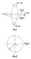
- a circular bi-convex lens As can be seem from Figure 2, the centre of the lens is marked by point C and an axis passing through this point C and projecting out of the page, or as shown in Figure 1, is termed the geometric axis. It is conventional in lenses that this axis is also the optical axis, by which is meant the axis joining the focal points of the lens. Conventionally, these two axes are coincident and the lens is generally symmetrical about point C. However, in order to avoid or minimise distortion, the lens need only be symmetrical about the optical axis and it has been found that if the geometric axis is displaced from the line of the optical axis, no undue distortion results.
- the thickness of the lens is determined by the thickness of the maximum edge, which must accommodate the injection process feed point, the lens may be overall made thinner. This is shown clearly in Figure 1.
- the feed point should always be on that size of the lens nearer the optical axis than the geometric axis.
- Lenses embodying the invention may be made by conventional moulding techniques, with the exception that the mould surfaces are shaped to correspond with these offset lens surfaces. Since the lens is less thick, the manufacturing time is reduced and hence the manufacturing costs are reduced.
- the surfaces of the lens may be spherical or aspheric, in either case being symmetrical about the optical axis.
- the amount of offset between the axes may be determined by the size of the maximum edge thickness required, the curvature of the lens, the overall dimensions of the lens, and the degree of thickness reduction desired. Quite small offsets between the axes can make considerable differences to the overall lens thickness.
- the minimum edge thickness is 1.574 mm and the maximum edge thickness is 4.655 mm, in each case for a lens of overall diameter 84 mm.
- the offset distance is 1.9445 mm, in another 2.56 mm.
- figures for edge thickness at various points on the circumference are given in the Table below.
Landscapes
- Physics & Mathematics (AREA)
- General Physics & Mathematics (AREA)
- Optics & Photonics (AREA)
- Moulds For Moulding Plastics Or The Like (AREA)
- Non-Silver Salt Photosensitive Materials And Non-Silver Salt Photography (AREA)
- Injection Moulding Of Plastics Or The Like (AREA)
- Window Of Vehicle (AREA)
- Glass Compositions (AREA)
- Testing Of Optical Devices Or Fibers (AREA)
- Lenses (AREA)
Claims (1)
- Verfahren zum Herstellen einer konvexen Linse, welches folgende Verfahrensschritte umfaßt: Erzeugen einer Gußform, deren innere Oberfläche die Form der herzustellenden Linse besitzt, wobei diese Form eine geometrische Achse besitzt, die der geometrischen Achse der herzustellenden Linse entspricht, welche Achse als diejenige Achse definiert ist, die durch die Linse am Mittelpunkt der Linse senkrecht zur allgemeinen Ebene der Linse geht, dadurch gekennzeichnet, daß wenigstens eine konkave Oberfläche der Form einen tiefsten Punkt besitzt, der von der geometrischen Achse entfernt ist, wobei die Form einen Einfüllpunkt besitzt, der sich an der Seitenkante der Form befindet, die sich näher bei dem tiefsten Punkt als bei der geometrischen Achse befindet, und Eingießen eines transparenten Plastikmaterials durch den Einfüllpunkt in den Gußformhohlraum.
Priority Applications (1)
| Application Number | Priority Date | Filing Date | Title |
|---|---|---|---|
| AT88300740T ATE76979T1 (de) | 1987-01-28 | 1988-01-28 | Linse. |
Applications Claiming Priority (2)
| Application Number | Priority Date | Filing Date | Title |
|---|---|---|---|
| GB8701879 | 1987-01-28 | ||
| GB8701879A GB2200762B (en) | 1987-01-28 | 1987-01-28 | Biconvex lens having offset optical and geometrical axes. |
Publications (2)
| Publication Number | Publication Date |
|---|---|
| EP0278638A1 EP0278638A1 (de) | 1988-08-17 |
| EP0278638B1 true EP0278638B1 (de) | 1992-06-03 |
Family
ID=10611347
Family Applications (1)
| Application Number | Title | Priority Date | Filing Date |
|---|---|---|---|
| EP88300740A Expired - Lifetime EP0278638B1 (de) | 1987-01-28 | 1988-01-28 | Linse |
Country Status (5)
| Country | Link |
|---|---|
| US (1) | US4836659A (de) |
| EP (1) | EP0278638B1 (de) |
| AT (1) | ATE76979T1 (de) |
| DE (1) | DE3871541T2 (de) |
| GB (1) | GB2200762B (de) |
Families Citing this family (1)
| Publication number | Priority date | Publication date | Assignee | Title |
|---|---|---|---|---|
| US5239416A (en) * | 1992-06-29 | 1993-08-24 | Optical Designs, Inc. | Variable power zoom stand magnifier |
Family Cites Families (4)
| Publication number | Priority date | Publication date | Assignee | Title |
|---|---|---|---|---|
| US2473588A (en) * | 1943-09-06 | 1949-06-21 | Combined Optical Ind Ltd | Method of molding lenses and like optical elements |
| GB710967A (en) * | 1950-10-11 | 1954-06-23 | Kurt Kirchhoff | Improvements in or relating to lens attachments for photographic cameras |
| US2906160A (en) * | 1958-11-07 | 1959-09-29 | Palley Stephen L St | Automatic gunsight |
| FR2128940A5 (de) * | 1971-03-09 | 1972-10-27 | Ducellier & Cie |
-
1987
- 1987-01-28 GB GB8701879A patent/GB2200762B/en not_active Revoked
-
1988
- 1988-01-28 AT AT88300740T patent/ATE76979T1/de active
- 1988-01-28 EP EP88300740A patent/EP0278638B1/de not_active Expired - Lifetime
- 1988-01-28 US US07/149,281 patent/US4836659A/en not_active Expired - Fee Related
- 1988-01-28 DE DE8888300740T patent/DE3871541T2/de not_active Expired - Fee Related
Also Published As
| Publication number | Publication date |
|---|---|
| GB2200762A (en) | 1988-08-10 |
| US4836659A (en) | 1989-06-06 |
| DE3871541D1 (de) | 1992-07-09 |
| GB2200762B (en) | 1990-12-05 |
| DE3871541T2 (de) | 1993-01-21 |
| GB8701879D0 (en) | 1987-03-04 |
| ATE76979T1 (de) | 1992-06-15 |
| EP0278638A1 (de) | 1988-08-17 |
Similar Documents
| Publication | Publication Date | Title |
|---|---|---|
| AU715443B2 (en) | Decentered noncorrective lens for eyewear | |
| JP2019120725A (ja) | レンズユニット及び金型の製造方法 | |
| JP2019120725A5 (de) | ||
| JPS6155452B2 (de) | ||
| US5213825A (en) | Plastic lens molding apparatus | |
| EP0278638B1 (de) | Linse | |
| JPH0961689A (ja) | 組立レンズ用の鏡枠 | |
| US5150547A (en) | Ophthalmic lens prism blocking ring | |
| US6338558B1 (en) | Spectacle lenses and a pair of spectacles using the same | |
| US3583785A (en) | Positive optical system | |
| JPS5848883B2 (ja) | セツゴウレンズ | |
| US5137344A (en) | Semi-finished lens | |
| JPS619601A (ja) | 光学レンズ | |
| JPS5939527A (ja) | プラスチツクレンズ | |
| JP2003337270A (ja) | レンズ保持枠 | |
| US3001448A (en) | Toric surface for the astigmatic correction of a shallow dome and prism combination | |
| JP2006276321A (ja) | 水中眼鏡及び水中眼鏡用レンズ | |
| EP3770663A1 (de) | Raumring, linsensystem, verfahren zur herstellung eines raumrings und verfahren zum zusammenbau eines linsensystems | |
| JPS6016895Y2 (ja) | 金属製眼鏡枠 | |
| JPH0554085B2 (de) | ||
| US4573777A (en) | Aspheric spectacle lens blank | |
| JPS63204208A (ja) | レンズ保持機構 | |
| JPH07117143A (ja) | モールドレンズ | |
| JPS56151902A (en) | Plastic lens | |
| JP4084919B2 (ja) | レンズの芯出し方法及びレンズの製造方法 |
Legal Events
| Date | Code | Title | Description |
|---|---|---|---|
| PUAI | Public reference made under article 153(3) epc to a published international application that has entered the european phase |
Free format text: ORIGINAL CODE: 0009012 |
|
| AK | Designated contracting states |
Kind code of ref document: A1 Designated state(s): AT BE DE FR GB IT NL SE |
|
| 17P | Request for examination filed |
Effective date: 19881122 |
|
| 17Q | First examination report despatched |
Effective date: 19900817 |
|
| GRAA | (expected) grant |
Free format text: ORIGINAL CODE: 0009210 |
|
| AK | Designated contracting states |
Kind code of ref document: B1 Designated state(s): AT BE DE FR GB IT NL SE |
|
| PG25 | Lapsed in a contracting state [announced via postgrant information from national office to epo] |
Ref country code: IT Free format text: LAPSE BECAUSE OF FAILURE TO SUBMIT A TRANSLATION OF THE DESCRIPTION OR TO PAY THE FEE WITHIN THE PRESCRIBED TIME-LIMIT;WARNING: LAPSES OF ITALIAN PATENTS WITH EFFECTIVE DATE BEFORE 2007 MAY HAVE OCCURRED AT ANY TIME BEFORE 2007. THE CORRECT EFFECTIVE DATE MAY BE DIFFERENT FROM THE ONE RECORDED. Effective date: 19920603 Ref country code: SE Effective date: 19920603 Ref country code: AT Effective date: 19920603 Ref country code: NL Effective date: 19920603 Ref country code: BE Effective date: 19920603 |
|
| REF | Corresponds to: |
Ref document number: 76979 Country of ref document: AT Date of ref document: 19920615 Kind code of ref document: T |
|
| REF | Corresponds to: |
Ref document number: 3871541 Country of ref document: DE Date of ref document: 19920709 |
|
| ET | Fr: translation filed | ||
| NLV1 | Nl: lapsed or annulled due to failure to fulfill the requirements of art. 29p and 29m of the patents act | ||
| PLBE | No opposition filed within time limit |
Free format text: ORIGINAL CODE: 0009261 |
|
| STAA | Information on the status of an ep patent application or granted ep patent |
Free format text: STATUS: NO OPPOSITION FILED WITHIN TIME LIMIT |
|
| 26N | No opposition filed | ||
| NLV4 | Nl: lapsed or anulled due to non-payment of the annual fee | ||
| REG | Reference to a national code |
Ref country code: GB Ref legal event code: IF02 |
|
| PGFP | Annual fee paid to national office [announced via postgrant information from national office to epo] |
Ref country code: FR Payment date: 20020110 Year of fee payment: 15 |
|
| PGFP | Annual fee paid to national office [announced via postgrant information from national office to epo] |
Ref country code: GB Payment date: 20020130 Year of fee payment: 15 |
|
| PGFP | Annual fee paid to national office [announced via postgrant information from national office to epo] |
Ref country code: DE Payment date: 20020227 Year of fee payment: 15 |
|
| PG25 | Lapsed in a contracting state [announced via postgrant information from national office to epo] |
Ref country code: GB Free format text: LAPSE BECAUSE OF NON-PAYMENT OF DUE FEES Effective date: 20030128 |
|
| PG25 | Lapsed in a contracting state [announced via postgrant information from national office to epo] |
Ref country code: DE Free format text: LAPSE BECAUSE OF NON-PAYMENT OF DUE FEES Effective date: 20030801 |
|
| GBPC | Gb: european patent ceased through non-payment of renewal fee | ||
| PG25 | Lapsed in a contracting state [announced via postgrant information from national office to epo] |
Ref country code: FR Free format text: LAPSE BECAUSE OF NON-PAYMENT OF DUE FEES Effective date: 20030930 |
|
| REG | Reference to a national code |
Ref country code: FR Ref legal event code: ST |