EP0277478B1 - Combat vehicle - Google Patents
Combat vehicle Download PDFInfo
- Publication number
- EP0277478B1 EP0277478B1 EP88100084A EP88100084A EP0277478B1 EP 0277478 B1 EP0277478 B1 EP 0277478B1 EP 88100084 A EP88100084 A EP 88100084A EP 88100084 A EP88100084 A EP 88100084A EP 0277478 B1 EP0277478 B1 EP 0277478B1
- Authority
- EP
- European Patent Office
- Prior art keywords
- magazine
- hull
- side rotary
- turret
- ammunition
- Prior art date
- Legal status (The legal status is an assumption and is not a legal conclusion. Google has not performed a legal analysis and makes no representation as to the accuracy of the status listed.)
- Expired - Lifetime
Links
Images
Classifications
-
- F—MECHANICAL ENGINEERING; LIGHTING; HEATING; WEAPONS; BLASTING
- F41—WEAPONS
- F41A—FUNCTIONAL FEATURES OR DETAILS COMMON TO BOTH SMALLARMS AND ORDNANCE, e.g. CANNONS; MOUNTINGS FOR SMALLARMS OR ORDNANCE
- F41A9/00—Feeding or loading of ammunition; Magazines; Guiding means for the extracting of cartridges
- F41A9/82—Reloading or unloading of magazines
-
- F—MECHANICAL ENGINEERING; LIGHTING; HEATING; WEAPONS; BLASTING
- F41—WEAPONS
- F41A—FUNCTIONAL FEATURES OR DETAILS COMMON TO BOTH SMALLARMS AND ORDNANCE, e.g. CANNONS; MOUNTINGS FOR SMALLARMS OR ORDNANCE
- F41A9/00—Feeding or loading of ammunition; Magazines; Guiding means for the extracting of cartridges
- F41A9/01—Feeding of unbelted ammunition
- F41A9/06—Feeding of unbelted ammunition using cyclically moving conveyors, i.e. conveyors having ammunition pusher or carrier elements which are emptied or disengaged from the ammunition during the return stroke
- F41A9/09—Movable ammunition carriers or loading trays, e.g. for feeding from magazines
- F41A9/10—Movable ammunition carriers or loading trays, e.g. for feeding from magazines pivoting or swinging
- F41A9/11—Movable ammunition carriers or loading trays, e.g. for feeding from magazines pivoting or swinging in a horizontal plane
-
- F—MECHANICAL ENGINEERING; LIGHTING; HEATING; WEAPONS; BLASTING
- F41—WEAPONS
- F41A—FUNCTIONAL FEATURES OR DETAILS COMMON TO BOTH SMALLARMS AND ORDNANCE, e.g. CANNONS; MOUNTINGS FOR SMALLARMS OR ORDNANCE
- F41A9/00—Feeding or loading of ammunition; Magazines; Guiding means for the extracting of cartridges
- F41A9/01—Feeding of unbelted ammunition
- F41A9/24—Feeding of unbelted ammunition using a movable magazine or clip as feeding element
- F41A9/26—Feeding of unbelted ammunition using a movable magazine or clip as feeding element using a revolving drum magazine
-
- F—MECHANICAL ENGINEERING; LIGHTING; HEATING; WEAPONS; BLASTING
- F41—WEAPONS
- F41A—FUNCTIONAL FEATURES OR DETAILS COMMON TO BOTH SMALLARMS AND ORDNANCE, e.g. CANNONS; MOUNTINGS FOR SMALLARMS OR ORDNANCE
- F41A9/00—Feeding or loading of ammunition; Magazines; Guiding means for the extracting of cartridges
- F41A9/61—Magazines
- F41A9/64—Magazines for unbelted ammunition
- F41A9/76—Magazines having an endless-chain conveyor
Definitions
- the invention relates to a combat vehicle with front-wheel drive, which has a vehicle trough and a turret with a gun and a front circulation magazine arranged in the area of the gun on the floor of the turret for large-caliber ammunition used standing.
- the object of the invention is to provide a mechanized and largely automated ammunition flow within the vehicle with the largest possible ammunition supply.
- This object is achieved in that on the floor of the vehicle trough behind the front, tower-side circulation magazine a largely filling the rear vehicle compartment, the standing ammunition-receiving circulation-side magazine is arranged and that between the two circulation magazines an empty position on the front circulation magazine from the rear circulation magazine occupying transfer device is provided.
- the invention takes advantage of the fact that in front-wheel-drive combat vehicles, the vehicle trough behind the gun is largely free of internals.
- This free space is used according to the invention for a correspondingly large ammunition store that a rear tub-side circulation magazine is arranged on the floor of the vehicle tub, which can hold a larger ammunition store and from which the ammunition can be converted into the tower-side circulation magazine by means of the transfer device.
- the tower-side circulation magazine can be controlled so that after each shot or after a few shots the empty positions are moved into the area of the transfer device in order to be filled with new ammunition from the tub-side circulation magazine so that there is always sufficient ammunition for one in the tower-side circulation magazine Battle task is available.
- the tub-side circulation magazine has a large number of smaller magazine units which are interchangeably inserted in the circulation magazine and are driven in such a way that, in conjunction with the drive movement of the tub-side circulation magazine, each position of the magazine unit can be moved into the movement path of the transfer device is.
- the tub-side circulation magazine can be easily re-ammunition.
- the large-caliber ammunition can be made available in small magazine units, inserted into the vehicle and inserted into the circulation magazine on the tub side. This enables quick and easy re-ammunition of the circulation magazine on the side of the tub.
- the tub-side circulation magazine is circular with a central drive and has a plurality of rotatable receptacles for one magazine unit each on a circle.
- the rear circulation magazine is thus designed in the manner of a large turret plate, on which in turn smaller magazine units in the form of turret plates are seated.
- the drive movements of both the circulation magazine and the magazine units are circular movements that are particularly easy to implement in terms of drive technology.
- Each magazine unit is preferably designed as a pallet, on which the cartridges are arranged standing in a circle.
- Each magazine unit has a transport bracket, by means of which it can be easily handled from the ammunition factory to the combat vehicle.
- a loading door or flap is expediently arranged in the region of the rear of the vehicle, the circulating magazine on the tub side having a holding position in the region of the loading door or flap.
- the loading door or flap can be opened either to the rear or upwards, so that the magazine units can be inserted into the vehicle pan from behind or from above and inserted into the circulation magazine.
- the transfer device consists of a transfer arm mounted on a vertical axis with at least one gripper for a projectile and that the transfer arm can be pivoted between a receiving position on the circulation magazine on the tub side and a delivery position on the circulation magazine on the tower side.
- the two circulation magazines are preferably arranged in such a way that their outer trajectories almost touch at one point in order to accommodate the largest possible ammunition supply in this way.
- the transfer device is then preferably also arranged, so that the ammunition can be transferred from the tub-side to the tower-side circulation magazine in the shortest possible way with the shortest possible time.
- the transfer arm can be arranged on a vertical column, which has the axis and is fastened to the vehicle pan. Instead, it is also possible for the transfer arm to be seated on a carriage which has the axle and can be moved horizontally between the tub-side and the tower-side circulation magazine on a guide on the vehicle pan, preferably the side wall thereof. The latter training is recommended if the two circulation magazines cannot be merged too closely due to the space or space requirements for the crew and consequently a larger transfer path has to be bridged.
- the two circulation magazines and the transfer device are advantageously linked to one another via a control system such that when an empty position on the tower-side circulation magazine enters the delivery position of the transfer device, an occupied position on the tub-side circulation magazine is always available in the receiving position. This enables a delay-free re-ammunition of the front circulation magazine.
- the front circulation magazine can be used with various types of large-caliber ammunition, e.g. B. explosive or fire ammunition.
- the tub-side circulation magazine has magazine units with correspondingly different types of ammunition, so that the tower-side circulation magazine can optionally be supplied with one or the other type of ammunition.
- the various types of ammunition and / or the magazine units receiving them are provided with sensors that indicate the type of ammunition, and the controller can have sensors to use the desired type of ammunition from the circulation magazine on the turret side at an empty position of the tower-side circulation magazine.
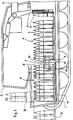
- the combat vehicle shown schematically in FIG. 1 has an armored vehicle hull 1 and a turret 2 rotatably mounted on the hull with a gun 3.
- a front circulation magazine 4 is arranged on the floor of the turret in the area of the turret 2, from which the large-caliber projectiles 5 can be removed by means of a loading device 6 and fed to the gun 3.
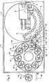
- the front circulation magazine 4 is, as can be seen from FIG. 2, formed in a part-circular loop which - as indicated by arrows - can be moved in both directions, namely between a position 7 for the loading device 6 (removal) and a transfer position 8 (receptacle ) a transfer device designated overall by 9.
- a rear circulation magazine 10 is arranged in direct connection to the front circulation magazine 4, which in the embodiment shown is designed as a centrally driven revolver magazine.
- the rear circulation magazine 10 has, on an outer arrangement circle, a multiplicity of smaller magazine units 11, which in turn are circular and each hold four storeys in the embodiment shown. These smaller magazine units are designed in the form of circular pallets, which in turn can be driven in their center 12.
- each projectile located on the magazine units can be moved into a receiving position 18, at which it is gripped by the transfer device 9 and into the transfer position 8 at the front Circulation magazine 4 can be implemented.
- the transfer device 9 consists of a vertical column 16 and a horizontal arm 17 mounted thereon with a gripper 18 which encompasses and clamps the projectile around the circumference and converts it from the solid position 15 into the transfer position 8 shown in dashed lines on the front circulation magazine 4 .
- the pallet-like magazine units 11 can accommodate various types of large-caliber ammunition in order to be able to fire various types of ammunition accordingly.
- the front circulation magazine 4, the rear circulation magazine 10 and the transfer device 9 are linked in terms of control in such a way that when an empty position on the front circulation magazine 4 is moved into the transfer position 8, a correspondingly occupied position on the rear circulation magazine 10 at the receiving position 18 is available to accommodate the position there To implement the projectile into the front circulation magazine 4 by means of the transfer device.
- both the projectiles and a corresponding number of positions in the front circulation magazine 4 can be provided with suitable sensors, for example to ensure that only a certain type of projectile can be used in these specific positions of the front circulation magazine 4.
- a loading door 19 opening to the rear or a loading flap opening upwards (not shown), through which the cartridge-like magazine units 11 are inserted into the vehicle pan and placed on corresponding receptacles of the rear circulation magazine 10 can be.
- the projectiles can already be placed on the empty pallets 11 in the ammunition factory or behind the front.
- These pallets have a transport liability, not shown, which is arranged, for example, in the center 12 of the pallet and by means of which the pallet can be gripped and transported.
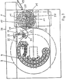
- the revolving magazine on the turret is drawn around in the front area below the weapon, while the space behind the weapon 3 is more accessible to the crew.
- the tray-side magazine 10 is moved back a little more and is smaller than in the embodiment according to FIG. 2.
- it has 11 individual receptacles 20 for projectiles between the rotatable magazine units, which fill the empty space between the magazine units.
- the transfer device has a carriage 21 on which the transfer arm 17 is mounted on an axis 22.
- the transfer arm 17 in turn has an axis 23 at the free end, on which the gripper 24 can be pivoted.
- the carriage 21 can be moved on a guide 25 which is arranged on the side wall 26 of the tub 1.
Abstract
Description
Die Erfindung betrifft ein Kampffahrzeug mit Frontantrieb, das eine Fahrzeugwanne und einen Turm mit Geschütz sowie ein im Bereich des Geschützes auf dem Boden der Turmbühne angeordnetes vorderes Umlaufmagazin für stehend eingesetzte, großkalibrige Munition aufweist.The invention relates to a combat vehicle with front-wheel drive, which has a vehicle trough and a turret with a gun and a front circulation magazine arranged in the area of the gun on the floor of the turret for large-caliber ammunition used standing.
Die Versorgung der Waffe eines Kampffahrzeugs mit kleinkalibriger Munition bietet heute kaum mehr Probleme. Diese kleinkalibrige Munition wird aufgereiht, z. B. an Gurten, transportiert, die über entsprechende Führungen in beliebigen Richtungen gefördert und umgelenkt werden können. Dabei bilden die Gurte sowohl die Halter, als auch das Transportmittel für die Munition. Großkalibrige Munition hingegen läßt sich wegen ihres Gewichtes und ihrer Größe nicht mehr mit Gurten fördern. Hier ist man deshalb bis heute weitgehend auf das manuelle Transportieren und Laden des Geschützes, also auf menschliche Kraft angewiesen. Abgesehen von der körperlichen Belastung erfordert dies in der Regel auch entsprechenden Freiraum innerhalb des Kampffahrzeugs. Hinzu kommen die nicht auszuschaltenden menschlichen Fehler.Nowadays, supplying the weapon of a combat vehicle with small-caliber ammunition hardly poses any problems. This small-caliber ammunition is lined up, e.g. B. transported on belts, which can be conveyed and deflected via appropriate guides in any direction. The straps form both the holder and the means of transport for the ammunition. Large-caliber ammunition, however, can no longer be conveyed with belts due to its weight and size. To this day, one is therefore largely dependent on the manual transport and loading of the gun, i.e. on human power. Aside from the physical strain, this usually also requires corresponding free space within the combat vehicle. Added to this are the human errors that cannot be eliminated.
Es hat deshalb nicht an Versuchen gefehlt, auch großkalibrige Munition innerhalb des Fahrzeugs zu magazinieren. So ist es beispielsweise bekannt, großkalibrige Munition im Heck des Fahrzeugturms so unterzubringen, daß sie sich nur über eine Indexposition automatisch in die Waffe überführen läßt. Aufgrund des beschränkten Raums im Geschützturm läßt sich dort auch nur ein beschränkter Munitionsvorrat unterbringen. Im übrigen muß das Turmmagazin von Hand aus der Fahrzeugwanne heraus oder von außen aufgefüllt werden.There has been no shortage of attempts to store large-caliber ammunition inside the vehicle. For example, it is known to accommodate large-caliber ammunition in the rear of the vehicle tower so that it can only be automatically transferred to the weapon via an index position. Due to the limited space in the turret, only a limited supply of ammunition can be accommodated there. In addition, the tower magazine must be filled out of the vehicle tub by hand or from the outside.
Bei dem eingangs genannten Fahrzeug ist es bekannt (WO-A 8 400 416), ein ringförmiges Umlaufmagazin unterhalb des Geschützturms auf der Turmbühne anzuordnen. Das Umlaufmagazin weist mehrere kleinere Ringmagazine auf. Die senkrechte Drehachse des Umlaufmagazins liegt etwa im Bereich des Verschlusses der Waffe. Im Bereich des Geschützes ist eine Ladeeinrichtung vorgesehen, die die im Umlaufmagazin stehend untergebrachte Munition entnimmt und durch entsprechende Bewegungsabläufe in die Seelenachse des Geschützrohrs bringt. Dieses Umlaufmagazin gestattet die Unterbringung eines größeren Munitionsvorrates in Geschütznähe und ferner eine automatische Entnahme und Übergabe der Munition an die Waffe. Auch dieses Umlaufmagazin muß aber vom Fahrzeugheck her manuell nachgefüllt werden, wobei jede einzelne Position des Umlaufmagazins gesondert mit einer Patrone besetzt werden muß.In the vehicle mentioned at the beginning, it is known (WO-A 8 400 416) to arrange an annular circulation magazine below the turret on the tower platform. The circulation magazine has several smaller ring magazines. The vertical axis of rotation of the circulation magazine lies approximately in the area of the weapon breech. A loading device is provided in the area of the gun, which takes the ammunition housed in the circulation magazine and brings them into the core axis of the gun barrel by means of corresponding movements. This circulation magazine allows the storage of a large ammunition reserve near the gun and also an automatic removal and transfer of the ammunition to the weapon. However, this circulation magazine also has to be refilled manually from the rear of the vehicle, with each individual position of the circulation magazine having to be filled separately with a cartridge.
Ausgehend von einem Kampffahrzeug des eingangs genannten Aufbaus liegt der Erfindung die Aufgabe zugrunde, innerhalb des Fahrzeugs bei größtmöglichem Munitionsvorrat für einen mechanisierten und weitgehend automatisierbaren Munitionsfluß zu sorgen.Starting from a combat vehicle of the construction mentioned in the introduction, the object of the invention is to provide a mechanized and largely automated ammunition flow within the vehicle with the largest possible ammunition supply.
Diese Aufgabe wird erfindungsgemäß dadurch gelöst, daß auf dem Boden der Fahrzeugwanne hinter dem vorderen, turmseitigen Umlaufmagazin ein den hinteren Fahrzeugraum weitgehend ausfüllendes, die Munition stehend aufnehmendes wannenseitiges Umlaufmagazin angeordnet ist und daß zwischen den beiden Umlaufmagazinen eine leere Positionen am vorderen Umlaufmagazin aus dem hinteren Umlaufmagazin besetzende Übergabeeinrichtung vorgesehen ist.This object is achieved in that on the floor of the vehicle trough behind the front, tower-side circulation magazine a largely filling the rear vehicle compartment, the standing ammunition-receiving circulation-side magazine is arranged and that between the two circulation magazines an empty position on the front circulation magazine from the rear circulation magazine occupying transfer device is provided.
Die Erfindung macht sich die Tatsache zunutze, daß bei Kampffahrzeugen mit Frontantrieb die Fahrzeugwanne hinter dem Geschütz weitgehend frei von Einbauten ist. Dieser Freiraum wird erfindungsgemäß dadurch für einen entsprechend großen Munitionsvorrat genutzt, daß auf dem Boden der Fahrzeugwanne ein hinteres wannenseitiges Umlaufmagazin angeordnet ist, das einen größeren Munitionsvorrat aufnehmen kann und aus dem die Munition mittels der Übergabeeinrichtung in das turmseitige Umlaufmagazin umgesetzt werden kann. Das turmseitige Umlaufmagazin kann so gesteuert werden, daß nach jedem Schuß oder nach einigen Schüssen die Leerpositionen in den Bereich der Übergabeeinrichtung bewegt werden, um dort aus dem wannenseitigen Umlaufmagazin wieder mit neuer Munition besetzt zu werden, so daß im turmseitigen Umlaufmagazin stets ausreichend Munition für eine Gefechtsaufgabe zur Verfügung steht.The invention takes advantage of the fact that in front-wheel-drive combat vehicles, the vehicle trough behind the gun is largely free of internals. This free space is used according to the invention for a correspondingly large ammunition store that a rear tub-side circulation magazine is arranged on the floor of the vehicle tub, which can hold a larger ammunition store and from which the ammunition can be converted into the tower-side circulation magazine by means of the transfer device. The tower-side circulation magazine can be controlled so that after each shot or after a few shots the empty positions are moved into the area of the transfer device in order to be filled with new ammunition from the tub-side circulation magazine so that there is always sufficient ammunition for one in the tower-side circulation magazine Battle task is available.
Vorzugsweise ist, wie an sich bekannt, vorgesehen, daß das wannenseitige Umlaufmagazin eine Vielzahl kleinerer Magazineinheiten aufweist, die in das Umlaufmagazin auswechselbar eingesetzt und derart angetrieben sind, daß in Verbindung mit der Antriebsbewegung des wannenseitigen Umlaufmagazins jede Position der Magazineinheit in die Bewegungsbahn der Übergabeeinrichtung bewegbar ist.Preferably, as is known per se, it is provided that the tub-side circulation magazine has a large number of smaller magazine units which are interchangeably inserted in the circulation magazine and are driven in such a way that, in conjunction with the drive movement of the tub-side circulation magazine, each position of the magazine unit can be moved into the movement path of the transfer device is.
Mit dieser Maßnahme kann das wannenseitige Umlaufmagazin in einfacher Weise nachmunitioniert werden. Es kann nämlich die großkalibrige Munition in kleinen Magazineinheiten bereitgestellt, in das Fahrzeug eingebracht und in das wannenseitige Umlaufmagazin eingesetzt werden. Dadurch ist ein schnelles und einfaches Nachmunitionieren des wannenseitigen Umlaufmagazins möglich. Selbstverständlich ist es auch möglich das Umlaufmagazin einzeln aufzumunitionieren.With this measure, the tub-side circulation magazine can be easily re-ammunition. This is because the large-caliber ammunition can be made available in small magazine units, inserted into the vehicle and inserted into the circulation magazine on the tub side. This enables quick and easy re-ammunition of the circulation magazine on the side of the tub. Of course, it is also possible to individually ammunition the circulation magazine.
In weiterer vorteilhafter, an sich jedoch bekannter Ausführung ist das wannenseitige Umlaufmagazin kreisförmig mit zentralem Antrieb ausgebildet und es weist auf einem Kreis eine Vielzahl von drehbaren Aufnahmen für je eine Magazineinheit auf.In a further advantageous, but known embodiment, the tub-side circulation magazine is circular with a central drive and has a plurality of rotatable receptacles for one magazine unit each on a circle.
Bei dieser Ausführungsform ist also das hintere Umlaufmagazin nach Art eines großen Revolvertellers ausgebildet, auf dem seinerseits wieder kleinere Magazineinheiten in Form von Revolvertellem sitzen. Die Antriebsbewegungen sowohl des Umlaufmagazins, als auch der Magazineinheiten sind jeweils antriebstechnisch besonders einfach zu verwirklichende Kreisbewegungen.In this embodiment, the rear circulation magazine is thus designed in the manner of a large turret plate, on which in turn smaller magazine units in the form of turret plates are seated. The drive movements of both the circulation magazine and the magazine units are circular movements that are particularly easy to implement in terms of drive technology.
Zur noch besseren Raumausnutzung kann vorgesehen sein, daß nahe der Peripherie des kreisförmigen, wannenseitigen Umlaufmagazins und zwischen den drehbaren Anfnahmen für je eine Magazineinheit Einzelaufnahmen für je ein Geschoß vorgesehen sind, die auf dem gleichen Kreis angeordnet sind, auf dem sich das am nächsten der Peripherie befindliche Geschoß der Magazineinheit befindet.For even better use of space it can be provided that near the periphery of the circular, tub-side circulation magazine and between the rotatable receptacles for one magazine unit, individual receptacles for each floor are provided, which are arranged on the same circle on which the closest to the periphery located floor of the magazine unit.
Vorzugsweise ist jede Magazineinheit als Palette ausgebildet, auf der die Patronen kreisförmig stehend angeordnet sind. Dabei weist jede Magazineinheit eine Transporthalterung auf, mittels der sie von der Munitionsfabrik bis zum Kampffahrzeug problemlos gehandhabt werden kann.Each magazine unit is preferably designed as a pallet, on which the cartridges are arranged standing in a circle. Each magazine unit has a transport bracket, by means of which it can be easily handled from the ammunition factory to the combat vehicle.
Zweckmäßigerweise ist im Bereich des Fahrzeughecks eine Ladetür oder -klappe angeordnet, wobei das wannenseitige umlaufmagazin eine Halteposition im Bereich der Ladetür oder -klappe aufweist.A loading door or flap is expediently arranged in the region of the rear of the vehicle, the circulating magazine on the tub side having a holding position in the region of the loading door or flap.
Die Ladetür bzw. -klappe kann entweder nach hinten oder nach oben geöffnet werden, so daß die Magazineinheiten von hinten oder von oben in die Fahrzeugwanne eingeführt und in das Umlaufmagazin eingesetzt werden können.The loading door or flap can be opened either to the rear or upwards, so that the magazine units can be inserted into the vehicle pan from behind or from above and inserted into the circulation magazine.
In weiterer vorteilhafter Ausgestaltung ist vorgesehen, daß die Übergabeeinrichtung aus einem an einer senkrechten Achse gelagerten öbergabearm mit wenigstens einem Greifer für ein Geschoß besteht und daß der Übergabearm zwischen einer Aufnahmeposition am wannenseitigen Umlaufmagazin und einer Abgabeposition am turmseitigen Umlaufmagazin schwenkbar ist.In a further advantageous embodiment, it is provided that the transfer device consists of a transfer arm mounted on a vertical axis with at least one gripper for a projectile and that the transfer arm can be pivoted between a receiving position on the circulation magazine on the tub side and a delivery position on the circulation magazine on the tower side.
Die beiden Umlaufmagazine werden vorzugsweise so angeordnet, daß sich ihre äußeren Bewegungsbahnen an einer Stelle annähernd berühren, um auf diese Weise einen größtmöglichen Munitionsvorrat unterbringen zu können. Im Bereich dieser größten Annäherung der Umlaufmagazine ist dann vorzugsweise auch die Übergabeeinrichtung angeordnet, so daß das Umsetzen der Munition aus dem wannenseitigen in das turmseitige Umlaufmagazin auf kürzestem Weg bei geringstem Zeitbedarf möglich ist.The two circulation magazines are preferably arranged in such a way that their outer trajectories almost touch at one point in order to accommodate the largest possible ammunition supply in this way. In the area of this greatest approximation of the circulation magazines, the transfer device is then preferably also arranged, so that the ammunition can be transferred from the tub-side to the tower-side circulation magazine in the shortest possible way with the shortest possible time.
Dabei kann der Übergabearm an einer senkrechten, die Achse aufweisenden, an der Fahrzeugwanne befestigten Säule angeordnet sein. Statt dessen ist es auch möglich, daß der Übergabearm auf einem die Achse aufweisenden Schlitten sitzt, der horizontal zwischen dem wannenseitigen und dem turmseitigen Umlaufmagazin auf einer Führung an der Fahrzeugwanne, vorzugsweise deren Seitenwand, verfahrbar ist. Die letztgenannte Ausbildung empfiehlt sich dann, wenn die beiden Umlaufmagazine bedingt durch die Platzverhältnisse bzw. den Raumbedarf für die Besatzung nicht allzu eng zusammengeführt werden können und folglich ein größerer übergabeweg zu überbrücken ist.The transfer arm can be arranged on a vertical column, which has the axis and is fastened to the vehicle pan. Instead, it is also possible for the transfer arm to be seated on a carriage which has the axle and can be moved horizontally between the tub-side and the tower-side circulation magazine on a guide on the vehicle pan, preferably the side wall thereof. The latter training is recommended if the two circulation magazines cannot be merged too closely due to the space or space requirements for the crew and consequently a larger transfer path has to be bridged.
Mit Vorteil sind die beiden Umlaufmagazine und die Übergabeeinrichtung über eine Steuerung derart miteinander verkettet, daß bei Einlaufen einer leeren Position am turmseitigen Umlaufmagazin in die Abgabeposition der Übergabeeinrichtung stets eine besetzte Position am wannenseitigen Umlaufmagazin in der Aufnahmeposition bereitsteht. Dadurch ist ein verzögerungsfreies Nachmunitionieren des vorderen Umlaufmagazins möglich.The two circulation magazines and the transfer device are advantageously linked to one another via a control system such that when an empty position on the tower-side circulation magazine enters the delivery position of the transfer device, an occupied position on the tub-side circulation magazine is always available in the receiving position. This enables a delay-free re-ammunition of the front circulation magazine.
Gemäß dem eingangs genannten bekannten Vorschlag (DE-P 36 27 042) kann das vordere Umlaufmagazin mit verschiedenartiger großkalibriger Munition, z. B. Sprengmunition oder Brandmunition ausgestattet sein. Bei einer solchen Ausrüstung ist erfindungsgemäß vorgesehen, daß das wannenseitige Umlaufmagazin Magazineinheiten mit entsprechend verschiedenartiger Munition aufweist, so daß das turmseitige Umlaufmagazin wahlweise mit der einen oder anderen Munitionsart versorgt werden kann.According to the known proposal mentioned at the beginning (DE-P 36 27 042), the front circulation magazine can be used with various types of large-caliber ammunition, e.g. B. explosive or fire ammunition. With such equipment, it is provided according to the invention that the tub-side circulation magazine has magazine units with correspondingly different types of ammunition, so that the tower-side circulation magazine can optionally be supplied with one or the other type of ammunition.
Dabei ist es von Vorteil, wenn die verschiedenartige Munition und/oder die sie aufnehmenden Magazineinheiten mit die Art der Munition indizierenden Sensoren versehen sind, wobei die Steuerung Aufnehmer aufweisen kann, um an einer Leerposition des turmseitigen Umlaufmagazins die gewünschte Munitionsart aus dem wannenseitigen Umlaufmagazin einzusetzen.It is advantageous if the various types of ammunition and / or the magazine units receiving them are provided with sensors that indicate the type of ammunition, and the controller can have sensors to use the desired type of ammunition from the circulation magazine on the turret side at an empty position of the tower-side circulation magazine.
Auf diese Weise ist es möglich, das turmseitige Umlaufmagazin je nach verschossener Munition aus dem wannenseitigen Umlaufmagazin wieder aufzufüllen.In this way it is possible to refill the revolving magazine on the tower side, depending on the ammunition fired, from the revolving magazine on the tub side.
Nachstehend ist die Erfindung anhand zweier in der Zeichnung dargestellten Ausführungsformen beschrieben. In der Zeichnung zeigen:
- Figur 1 einen schematischen, teilweise abgebrochenen Schnitt durch ein Kampffahrzeug;
Figur 2 eine Draufsicht auf die Fahrzeugwanne undFigur 3 eine Draufsicht auf die Fahrzeugwanne mit einer abgewandelten Ausführungsform.
- Figure 1 is a schematic, partially broken section through a combat vehicle;
- Figure 2 is a plan view of the vehicle pan and
- Figure 3 is a plan view of the vehicle pan with a modified embodiment.
Das in Figur 1 schematisch wiedergegebene Kampffahrzeug weist eine gepanzerte Fahrzeugwanne 1 und einen auf der Wanne drehbar gelagerten Geschützturm 2 mit einem Geschütz 3 auf. Auf dem Boden der Turmbühne im Bereich des Geschützturms 2 ist ein vorderes Umlaufmagazin 4 angeordnet, aus dem die großkalibrigen Geschosse 5 mittels einer Ladeeinrichtung 6 entnommen und dem Geschütz 3 zugeführt werden können.The combat vehicle shown schematically in FIG. 1 has an armored vehicle hull 1 and a
Das vordere Umlaufmagazin 4 ist, wie aus Figur 2 ersichtlich, in einer teilkreisförmigen Schleife ausgebildet, die - wie mit Pfeilen angedeutet - in beiden Richtungen bewegbar ist, und zwar zwischen einer Position 7 für die Ladeeinrichtung 6 (Entnahme) und einer Übergabeposition 8 (Aufnahnie) einer insgesamt mit 9 bezeichneten Übergabeeinrichtung.The
Im hinteren Bereich der Fahrzeugwanne ist im unmittelbaren Anschluß an das vordere Umlaufmagazin 4 ein hinteres Umlaufmagazin 10 angeordnet, das beim gezeigten Ausführungsbeispiel als zentral angetriebenes Revolvermagazin ausgebildet ist. Das hintere Umlaufmagazin 10 weist auf einem äußeren Anordnungskreis eine Vielzahl kleinerer Magazineinheiten 11 auf, die wiederum kreisförmig ausgebildet sind und in der gezeigten Ausführung jeweils vier Geschosse aufnehmen. Diese kleineren Magazineinheiten sind in Form von Kreispaletten ausgebildet, die wiederum in ihrem Zentrum 12 antreibbar sind.In the rear area of the vehicle trough, a
Mittels der mit Pfeil 13 angedeuteten Drehbewegung des hinteren Umlaufmagazins 10 und der mit Pfeil 14 angedeuteten Drehbewegung der palettenartigen Magazineinheiten läßt sich jedes auf den Magazineinheiten befindliche Geschoß in eine Aufnahmeposition 18 bewegen, an der es von der Übergabeeinrichtung 9 ergriffen und in die Übergabeposition 8 am vorderen Umlaufmagazin 4 umgesetzt werden kann.By means of the rotary movement of the
Die Übergabeeinrichtung 9 besteht beim gezeigten Ausführungsbeispiel aus einer senkrechten Säule 16 und einem daran gelagerten horizontalen Arm 17 mit einem Greifer 18, der das Geschoß am Umfang umfaßt und einspannt und aus der durchgezogen wiedergegebenen Aufnahmeposition 15 in die gestrichelt wiedergegebene Übergabeposition 8 am vorderen Umlaufmagazin 4 umsetzt.In the exemplary embodiment shown, the
Gegebenenfalls können die palettenartigen Magazineinheiten 11 verschiedenartige großkalibrige Munition aufnehmen, um entsprechend verschiedenartige Munition verschießen zu können. Ferner sind das vordere Umlaufmagazin 4, das hintere Umlaufmagazin 10 und die Übergabeeinrichtung 9 steuerungsmäßig so verkettet, daß bei Einfahren einer Leerposition am vorderen Umlaufmagazin 4 in die Übergabeposition 8 eine entsprechend besetzte Position am hinteren Umlaufmagazin 10 an der Aufnahmeposition 18 bereitsteht, um das dort befindliche Geschoß mittels der Übergabeeinrichtung in das vordere Umlaufmagazin 4 umzusetzen.If necessary, the pallet-
Bei verschiedenartiger Munition können sowohl die Geschosse, als auch eine entsprechende Anzahl von Positionen im vorderen Umlaufmagazin 4 mit geeigneten Sensoren versehen sein, um beispielsweise sicherzustellen, daß in diese bestimmten Positionen des vorderen Umlaufmagazins 4 jeweils nur eine bestimmte Geschoßart eingesetzt werden kann. Statt dessen ist es aber auch möglich, die beiden Umlaufmagazine 4, 10 von der Geschützsteuerung aus so anzusteuern, daß die am Geschütz jeweils angeforderte Munition in entsprechender Reihenfolge im Umlaufmagazin 4 bereitgestellt wird.In the case of different types of ammunition, both the projectiles and a corresponding number of positions in the
Wie in Figur 2 schematisch dargestellt, ist im Bereich des Fahrzeughecks eine entweder nach hinten öffnende Ladetür 19 oder eine nach oben öffnende Ladeklappe (nicht gezeigt) vorgesehen, durch die die patettenartigen Magazineinheiten 11 in die Fahrzeugwanne eingebracht und auf entsprechende Aufnahmen des hinteren Umlaufmagazins 10 aufgesetzt werden können. Die Geschosse können bereits in der Munitionsfabrik oder aber hinter der Front auf die leeren Paletten 11 aufgesetzt werden. Diese Paletten weisen eine nicht gezeigte Transporthafterung auf, die beispielsweise im Zentrum 12 der Palette angeordnet ist und mittels der die Palette ergriffen und transportiert werden kann.As shown schematically in FIG. 2, in the area of the rear of the vehicle there is provided either a
Bei der Ausführungsform gemäß Figur 3 sind gleiche bzw. funktionsgleiche Teile mit gleichen Bezugszeichen versehen. Das turmseitige Umlaufmagazin ist im vorderen Bereich unterhalb der waffe herumgezogen, während der Raum hinter der Waffe 3 für die Besatzung besser zugänglich ist. Das wannenseitige Magazin 10 ist etwas stärker nach hinten abgerückt und kleiner ausgebildet als bei der Ausführungsform gemäß Figur 2. Dafür besitzt es zwischen den drehbaren Magazineinheiten 11 Einzelaufnahmen 20 für Geschosse, die den Leerraum zwischen den Magazineinheiten ausfüllen.In the embodiment according to FIG. 3, identical or functionally identical parts are provided with the same reference symbols. The revolving magazine on the turret is drawn around in the front area below the weapon, while the space behind the
Die Übergabeeinrichtung weist statt der Säule 16 der Figur 2 einen Schlitten 21 auf, an dem der Übergabearm 17 an einer Achse 22 gelagert ist. Der Ubergabearm 17 weist seinerseits am freien Ende eine Achse 23 auf, an dem der Greifer 24 schwenkbar ist. Der Schlitten 21 ist auf einer Führung 25 verfahrbar, die an der Seitenwand 26 der Wanne 1 angeordnet ist.Instead of the
Mit der erfindungsgemäßen Ausbildung ist ein mechanisierter und weitgehend automatisierbarer Munitionsfluß innerhalb eines Kampffahrzeugs bei größtmöglichem Munitionsvorrat gegeben. Auch das Nachmunitionieren läßt sich weitgehend mechanisieren.With the design according to the invention, a mechanized and largely automatable ammunition flow within a combat vehicle is provided with the largest possible ammunition supply. Re-ammunition can also be largely mechanized.
Claims (13)
Applications Claiming Priority (2)
| Application Number | Priority Date | Filing Date | Title |
|---|---|---|---|
| DE19873701091 DE3701091A1 (en) | 1987-01-16 | 1987-01-16 | FIGHTING VEHICLE |
| DE3701091 | 1987-01-16 |
Publications (2)
| Publication Number | Publication Date |
|---|---|
| EP0277478A1 EP0277478A1 (en) | 1988-08-10 |
| EP0277478B1 true EP0277478B1 (en) | 1990-04-18 |
Family
ID=6318923
Family Applications (1)
| Application Number | Title | Priority Date | Filing Date |
|---|---|---|---|
| EP88100084A Expired - Lifetime EP0277478B1 (en) | 1987-01-16 | 1988-01-07 | Combat vehicle |
Country Status (3)
| Country | Link |
|---|---|
| US (1) | US4966064A (en) |
| EP (1) | EP0277478B1 (en) |
| DE (2) | DE3701091A1 (en) |
Families Citing this family (12)
| Publication number | Priority date | Publication date | Assignee | Title |
|---|---|---|---|---|
| DE3723699A1 (en) * | 1986-08-12 | 1989-02-02 | Porsche Ag | Device for loading a gun |
| DE3922317A1 (en) * | 1989-07-07 | 1991-01-17 | Wegmann & Co | MISSILE TRANSPORTER, ESPECIALLY FOR A COMBAT VEHICLE |
| DE4126688C1 (en) * | 1991-08-13 | 1996-09-19 | Wegmann & Co Gmbh | Battle tank with unmanned rotatable turret |
| DE19526664A1 (en) * | 1995-07-21 | 1997-01-23 | Kuka Wehrtechnik Gmbh | Tower for a wheeled or tracked vehicle |
| SE519911C2 (en) * | 2000-08-25 | 2003-04-22 | Alvis Haegglunds Ab | The weapon tower for a combat unit |
| WO2003025494A1 (en) * | 2001-08-30 | 2003-03-27 | Krauss-Maffei Wegmann Gmbh & Co. Kg | Artillery gun with a heavy weapon arranged on a support vehicle |
| SE520361C2 (en) * | 2001-12-05 | 2003-07-01 | Alvis Haegglunds Ab | Device for transferring coarse-caliber ammunition from an ammunition magazine to a charging position on a coarse-caliber weapon |
| US20070006724A1 (en) * | 2005-05-20 | 2007-01-11 | Strong Russell W | A mobile gunner station |
| US8162262B2 (en) * | 2007-07-31 | 2012-04-24 | The Boeing Company | Reconfigurable aircraft and associated methods |
| US8231083B2 (en) * | 2007-10-18 | 2012-07-31 | The Boeing Company | System and methods for airborne launch and recovery of aircraft |
| IT1400444B1 (en) | 2010-06-08 | 2013-05-31 | Oto Melara Spa | STORAGE SYSTEM FOR ARTILLERY AMMUNITIONS AND PROGRAM FOR ASSOCIATED PROCESSORS. |
| DE102019101906B3 (en) * | 2019-01-25 | 2020-07-09 | Krauss-Maffei Wegmann Gmbh & Co. Kg | Ammunition delivery system |
Family Cites Families (14)
| Publication number | Priority date | Publication date | Assignee | Title |
|---|---|---|---|---|
| US1565837A (en) * | 1924-10-01 | 1925-12-15 | Webster Thomas Herbert | Ammunition supply apparatus for gun turrets |
| US2971438A (en) * | 1951-05-11 | 1961-02-14 | Paul L Fox | Off-mount magazine ammunition transfer mechanism |
| US3075434A (en) * | 1952-08-27 | 1963-01-29 | Jean W Hickman | Ammunition transfer mechanism |
| SE408476B (en) * | 1974-10-18 | 1979-06-11 | Bofors Ab | SPECIAL FOR TANK WITH GROSS CALIBRIC FIREARMS INTENDED MAGAZINE |
| BR8103150A (en) * | 1980-05-23 | 1982-02-09 | Creusot Loire | DEVICE FOR TRANSPORTING A SEQUENCE OF CYLINDRICAL OBJECTS, LIKE MUNICIPALITY |
| DE3042675A1 (en) * | 1980-11-12 | 1982-06-16 | Ficht GmbH, 8011 Kirchseeon | Armoured vehicle gun loading equipment - has rotary plate supporting rounds upright parallel to axis of rotation |
| DE3111514A1 (en) * | 1981-03-24 | 1982-10-28 | Diehl GmbH & Co, 8500 Nürnberg | Loading device for a moving gun (weapon with a barrel) which is installed in an armoured vehicle |
| DE3132631A1 (en) * | 1981-08-18 | 1983-03-03 | Krauss-Maffei AG, 8000 München | Rotary magazine |
| US4495853A (en) * | 1982-07-13 | 1985-01-29 | Fmc Corporation | Fixed elevation automatic loading system for fixed ammunition |
| DE3332225A1 (en) * | 1983-09-07 | 1985-03-21 | Rheinmetall GmbH, 4000 Düsseldorf | ARMORED VEHICLE AS A PROPELLED AMMUNITION AND TEAM TRANSPORTER |
| US4671164A (en) * | 1985-05-03 | 1987-06-09 | Ares, Inc. | Shell magazine for tanks |
| AT385594B (en) * | 1985-10-03 | 1988-04-25 | Steyr Daimler Puch Ag | DEVICE FOR SUPPLYING THE CANNON OF AN AMMUNIZED VEHICLE |
| US4700609A (en) * | 1985-10-04 | 1987-10-20 | Fmc Corporation | Autoloader for military vehicle |
| DE3627042A1 (en) * | 1986-08-09 | 1988-02-11 | Kuka Wehrtechnik Gmbh | DEVICE FOR LOADING GUNS, IN PARTICULAR HOWBOWS |
-
1987
- 1987-01-16 DE DE19873701091 patent/DE3701091A1/en not_active Withdrawn
-
1988
- 1988-01-07 DE DE8888100084T patent/DE3860094D1/en not_active Expired - Fee Related
- 1988-01-07 EP EP88100084A patent/EP0277478B1/en not_active Expired - Lifetime
-
1989
- 1989-11-17 US US07/467,752 patent/US4966064A/en not_active Expired - Fee Related
Also Published As
| Publication number | Publication date |
|---|---|
| US4966064A (en) | 1990-10-30 |
| DE3701091A1 (en) | 1988-07-28 |
| DE3860094D1 (en) | 1990-05-23 |
| EP0277478A1 (en) | 1988-08-10 |
Similar Documents
| Publication | Publication Date | Title |
|---|---|---|
| EP0178484B1 (en) | Loading device for ordnances | |
| EP0277478B1 (en) | Combat vehicle | |
| DE2826136C3 (en) | Device for the transport of ammunition from an armored vehicle to a top-mounted gun fixed on a platform | |
| DE2501425C2 (en) | Bullet feeding device on a weapon-carrying vehicle | |
| DE3320241A1 (en) | AUTOMATIC CHARGER FOR A TANK VEHICLE WITH TURNTABLE TANK | |
| DE3041866C2 (en) | Device for transporting ammunition from an ammunition container for locking a weapon | |
| DE3702603C2 (en) | ||
| DE3642920C2 (en) | Loading device for a combat vehicle, in particular a self-propelled howitzer | |
| EP0256250B1 (en) | Device for loading cannons, especially armour-plated cannons | |
| DE2501424C2 (en) | Ammunition receiving and loading device for a large-caliber firearm | |
| DE3022410C2 (en) | Device for feeding projectile ammunition in an armored vehicle | |
| DE3702426C2 (en) | ||
| DE4205963A1 (en) | TANK HOOD | |
| DE3701713C2 (en) | ||
| DE3016928C2 (en) | ||
| DE69721037T2 (en) | METHOD AND DEVICE FOR HANDLING DRIFT CHARGES THAT HAVE DIFFERENT PERFORMANCES AND DIMENSIONS | |
| DE3722353A1 (en) | FIGHTING VEHICLE | |
| DE3111514C2 (en) | ||
| DE2413983A1 (en) | Automatic loader for armoured fighting vehicle gun - has drum with ammunition compartments indexed as required to gun barrel | |
| DE60200660T2 (en) | Method and apparatus for ammunition loading for a gun located in a ship | |
| DE4123338A1 (en) | Ammunition magazine for armoured fighting vehicle - is in form of rotating drum and brings ammunition in line with gun axis | |
| EP0635695B1 (en) | Fighting vehicle, in particular howitzer, with ammunition magazines | |
| DE3042675A1 (en) | Armoured vehicle gun loading equipment - has rotary plate supporting rounds upright parallel to axis of rotation | |
| DE1428711C1 (en) | Gun loading device, especially for guns mounted on vehicles | |
| DE2127428A1 (en) | Loading device for weapons for continuous firing of various types of ammunition |
Legal Events
| Date | Code | Title | Description |
|---|---|---|---|
| PUAI | Public reference made under article 153(3) epc to a published international application that has entered the european phase |
Free format text: ORIGINAL CODE: 0009012 |
|
| AK | Designated contracting states |
Kind code of ref document: A1 Designated state(s): BE CH DE ES FR GB GR IT LI NL SE |
|
| 17P | Request for examination filed |
Effective date: 19880708 |
|
| 17Q | First examination report despatched |
Effective date: 19890614 |
|
| GRAA | (expected) grant |
Free format text: ORIGINAL CODE: 0009210 |
|
| AK | Designated contracting states |
Kind code of ref document: B1 Designated state(s): BE CH DE ES FR GB GR IT LI NL SE |
|
| PG25 | Lapsed in a contracting state [announced via postgrant information from national office to epo] |
Ref country code: SE Effective date: 19900418 Ref country code: GR Free format text: LAPSE BECAUSE OF FAILURE TO SUBMIT A TRANSLATION OF THE DESCRIPTION OR TO PAY THE FEE WITHIN THE PRESCRIBED TIME-LIMIT Effective date: 19900418 Ref country code: ES Free format text: THE PATENT HAS BEEN ANNULLED BY A DECISION OF A NATIONAL AUTHORITY Effective date: 19900418 |
|
| REF | Corresponds to: |
Ref document number: 3860094 Country of ref document: DE Date of ref document: 19900523 |
|
| ITF | It: translation for a ep patent filed |
Owner name: DR. ING. A. RACHELI & C. |
|
| ET | Fr: translation filed | ||
| GBT | Gb: translation of ep patent filed (gb section 77(6)(a)/1977) | ||
| PLBE | No opposition filed within time limit |
Free format text: ORIGINAL CODE: 0009261 |
|
| STAA | Information on the status of an ep patent application or granted ep patent |
Free format text: STATUS: NO OPPOSITION FILED WITHIN TIME LIMIT |
|
| 26N | No opposition filed | ||
| ITTA | It: last paid annual fee | ||
| PGFP | Annual fee paid to national office [announced via postgrant information from national office to epo] |
Ref country code: BE Payment date: 19931213 Year of fee payment: 7 |
|
| PGFP | Annual fee paid to national office [announced via postgrant information from national office to epo] |
Ref country code: FR Payment date: 19931215 Year of fee payment: 7 |
|
| PGFP | Annual fee paid to national office [announced via postgrant information from national office to epo] |
Ref country code: GB Payment date: 19940106 Year of fee payment: 7 |
|
| PGFP | Annual fee paid to national office [announced via postgrant information from national office to epo] |
Ref country code: NL Payment date: 19940131 Year of fee payment: 7 |
|
| PGFP | Annual fee paid to national office [announced via postgrant information from national office to epo] |
Ref country code: DE Payment date: 19940219 Year of fee payment: 7 |
|
| PGFP | Annual fee paid to national office [announced via postgrant information from national office to epo] |
Ref country code: CH Payment date: 19940330 Year of fee payment: 7 |
|
| PG25 | Lapsed in a contracting state [announced via postgrant information from national office to epo] |
Ref country code: GB Effective date: 19950107 |
|
| PG25 | Lapsed in a contracting state [announced via postgrant information from national office to epo] |
Ref country code: LI Effective date: 19950131 Ref country code: CH Effective date: 19950131 Ref country code: BE Effective date: 19950131 |
|
| BERE | Be: lapsed |
Owner name: KUKA WEHRTECHNIK G.M.B.H. Effective date: 19950131 |
|
| PG25 | Lapsed in a contracting state [announced via postgrant information from national office to epo] |
Ref country code: NL Effective date: 19950801 |
|
| GBPC | Gb: european patent ceased through non-payment of renewal fee |
Effective date: 19950107 |
|
| PG25 | Lapsed in a contracting state [announced via postgrant information from national office to epo] |
Ref country code: FR Effective date: 19950929 |
|
| REG | Reference to a national code |
Ref country code: CH Ref legal event code: PL |
|
| NLV4 | Nl: lapsed or anulled due to non-payment of the annual fee |
Effective date: 19950801 |
|
| PG25 | Lapsed in a contracting state [announced via postgrant information from national office to epo] |
Ref country code: DE Effective date: 19951003 |
|
| REG | Reference to a national code |
Ref country code: FR Ref legal event code: ST |
|
| PG25 | Lapsed in a contracting state [announced via postgrant information from national office to epo] |
Ref country code: IT Free format text: LAPSE BECAUSE OF NON-PAYMENT OF DUE FEES;WARNING: LAPSES OF ITALIAN PATENTS WITH EFFECTIVE DATE BEFORE 2007 MAY HAVE OCCURRED AT ANY TIME BEFORE 2007. THE CORRECT EFFECTIVE DATE MAY BE DIFFERENT FROM THE ONE RECORDED. Effective date: 20050107 |