EP0276972B1 - Handhabenzusammenbau - Google Patents
Handhabenzusammenbau Download PDFInfo
- Publication number
- EP0276972B1 EP0276972B1 EP88300610A EP88300610A EP0276972B1 EP 0276972 B1 EP0276972 B1 EP 0276972B1 EP 88300610 A EP88300610 A EP 88300610A EP 88300610 A EP88300610 A EP 88300610A EP 0276972 B1 EP0276972 B1 EP 0276972B1
- Authority
- EP
- European Patent Office
- Prior art keywords
- handle
- closure member
- handle assembly
- assembly
- restraint
- Prior art date
- Legal status (The legal status is an assumption and is not a legal conclusion. Google has not performed a legal analysis and makes no representation as to the accuracy of the status listed.)
- Expired - Lifetime
Links
- 230000000717 retained effect Effects 0.000 claims description 2
- 230000000994 depressogenic effect Effects 0.000 description 2
- 238000000034 method Methods 0.000 description 2
- 239000003973 paint Substances 0.000 description 2
- 238000010422 painting Methods 0.000 description 2
- 230000003014 reinforcing effect Effects 0.000 description 2
- 229910001369 Brass Inorganic materials 0.000 description 1
- BQCADISMDOOEFD-UHFFFAOYSA-N Silver Chemical compound [Ag] BQCADISMDOOEFD-UHFFFAOYSA-N 0.000 description 1
- 239000010951 brass Substances 0.000 description 1
- 230000000295 complement effect Effects 0.000 description 1
- 238000005242 forging Methods 0.000 description 1
- 238000012423 maintenance Methods 0.000 description 1
- 238000004519 manufacturing process Methods 0.000 description 1
- 230000004048 modification Effects 0.000 description 1
- 238000012986 modification Methods 0.000 description 1
- 238000007591 painting process Methods 0.000 description 1
- 229910052709 silver Inorganic materials 0.000 description 1
- 239000004332 silver Substances 0.000 description 1
- 239000007787 solid Substances 0.000 description 1
Images


Classifications
-
- E—FIXED CONSTRUCTIONS
- E05—LOCKS; KEYS; WINDOW OR DOOR FITTINGS; SAFES
- E05B—LOCKS; ACCESSORIES THEREFOR; HANDCUFFS
- E05B3/00—Fastening knobs or handles to lock or latch parts
-
- E—FIXED CONSTRUCTIONS
- E05—LOCKS; KEYS; WINDOW OR DOOR FITTINGS; SAFES
- E05B—LOCKS; ACCESSORIES THEREFOR; HANDCUFFS
- E05B9/00—Lock casings or latch-mechanism casings ; Fastening locks or fasteners or parts thereof to the wing
- E05B9/08—Fastening locks or fasteners or parts thereof, e.g. the casings of latch-bolt locks or cylinder locks to the wing
- E05B9/082—Fastening locks or fasteners or parts thereof, e.g. the casings of latch-bolt locks or cylinder locks to the wing with concealed screws
-
- E—FIXED CONSTRUCTIONS
- E05—LOCKS; KEYS; WINDOW OR DOOR FITTINGS; SAFES
- E05B—LOCKS; ACCESSORIES THEREFOR; HANDCUFFS
- E05B85/00—Details of vehicle locks not provided for in groups E05B77/00 - E05B83/00
- E05B85/10—Handles
-
- Y—GENERAL TAGGING OF NEW TECHNOLOGICAL DEVELOPMENTS; GENERAL TAGGING OF CROSS-SECTIONAL TECHNOLOGIES SPANNING OVER SEVERAL SECTIONS OF THE IPC; TECHNICAL SUBJECTS COVERED BY FORMER USPC CROSS-REFERENCE ART COLLECTIONS [XRACs] AND DIGESTS
- Y10—TECHNICAL SUBJECTS COVERED BY FORMER USPC
- Y10S—TECHNICAL SUBJECTS COVERED BY FORMER USPC CROSS-REFERENCE ART COLLECTIONS [XRACs] AND DIGESTS
- Y10S292/00—Closure fasteners
- Y10S292/37—Push button operators
-
- Y—GENERAL TAGGING OF NEW TECHNOLOGICAL DEVELOPMENTS; GENERAL TAGGING OF CROSS-SECTIONAL TECHNOLOGIES SPANNING OVER SEVERAL SECTIONS OF THE IPC; TECHNICAL SUBJECTS COVERED BY FORMER USPC CROSS-REFERENCE ART COLLECTIONS [XRACs] AND DIGESTS
- Y10—TECHNICAL SUBJECTS COVERED BY FORMER USPC
- Y10S—TECHNICAL SUBJECTS COVERED BY FORMER USPC CROSS-REFERENCE ART COLLECTIONS [XRACs] AND DIGESTS
- Y10S292/00—Closure fasteners
- Y10S292/53—Mounting and attachment
-
- Y—GENERAL TAGGING OF NEW TECHNOLOGICAL DEVELOPMENTS; GENERAL TAGGING OF CROSS-SECTIONAL TECHNOLOGIES SPANNING OVER SEVERAL SECTIONS OF THE IPC; TECHNICAL SUBJECTS COVERED BY FORMER USPC CROSS-REFERENCE ART COLLECTIONS [XRACs] AND DIGESTS
- Y10—TECHNICAL SUBJECTS COVERED BY FORMER USPC
- Y10S—TECHNICAL SUBJECTS COVERED BY FORMER USPC CROSS-REFERENCE ART COLLECTIONS [XRACs] AND DIGESTS
- Y10S292/00—Closure fasteners
- Y10S292/64—Assembly
-
- Y—GENERAL TAGGING OF NEW TECHNOLOGICAL DEVELOPMENTS; GENERAL TAGGING OF CROSS-SECTIONAL TECHNOLOGIES SPANNING OVER SEVERAL SECTIONS OF THE IPC; TECHNICAL SUBJECTS COVERED BY FORMER USPC CROSS-REFERENCE ART COLLECTIONS [XRACs] AND DIGESTS
- Y10—TECHNICAL SUBJECTS COVERED BY FORMER USPC
- Y10T—TECHNICAL SUBJECTS COVERED BY FORMER US CLASSIFICATION
- Y10T292/00—Closure fasteners
- Y10T292/57—Operators with knobs or handles
Definitions
- the present invention relates to a handle assembly particularly, but not exclusively, for a vehicle door.
- An object of the present invention is to alleviate these problems.
- a handle assembly for a closure member comprising a handle having a portion which may be resiliently moved in relation to the remainder of the handle between a first inoperative position and a second operative position in which a closure member to which the handle is attached may be opened, characterised by means for connecting the handle assembly to the closure member, said means comprising further means for connecting the handle assembly to the closure member from externally of the closure member, access to said further means being prevented by the handle when the handle is connected to the closure member, said means for connecting comprising a restraint preventing removal of the portion and thereby also the remainder of the handle and said restraint being accessible only when the closure member is in an open position.
- the handle is connected to the door by connecting members such as screws which screw into a substantially plate form member connected to the interior face of the closure member.
- the portion of the handle is a button which fits into an aperture defined by the remainder of the handle. This button is spring loaded.
- a rod extends from the underside of the button which is formed for engagement with a trap plate which constitutes the restraint. This trap plate sits underneath the button and is drawn into the operative position when the button is depressed against its spring by a screw extending through the shut face of the closure member (door).
- the button is released it is retained in the remainder of the handle by the trap plate.
- this screw which is only accessible when the door is open, the button can be released thus allowing access to the screws connecting the handle to the door.
- the handle may then be removed from externally of the door thus greatly facilitating maintenance.
- the handle assembly comprises a handle 1 defining an aperture 1A at one end in which a push button 5 is disposed.
- the handle 1 is connected to a base plate 2 which is connected to the door panel 25 on which the handle is to be mounted.
- a gasket 4 is fitted around the base plate 2 to protect the paint on the panel 25.
- a sub-assembly comprising a reinforcing plate 13, a clinch nut 14, a pivot mounting bracket 19 and a clamp bracket 15 is provided on the underside of the door panel to the interior of the automobile.
- This sub-assembly is shaped to receive through an aperture in the door panel 25 a trap plate 17 of substantially inverted 'L' shaped cross section.
- the reinforcing plate 13, clinch nut 14 and clamp bracket 15 are connected to the underside of the door panel in a pre-assembly operation.
- the pivot mounting bracket 19 is connected to the plate 13 by a screw 18 extending from the exterior of the door panel through an aperture 26 in the panel 25 into a screw threaded boss 27 on the bracket 19.
- the trap plate 17 is then fitted through a slot 28 in the skin of the door panel and through slots 29 in the plate 13.
- Plate 17 rests on plate 13 and is allowed to slide when trapped between the plate and the base plate 2 due to a boss 30 formed on the underside of the plate 2 which extends through an aperture 31 formed in the plate 17.
- the handle pivots at the front about a pin 3, which is attached to the base plate 2, the geometry of this hinge enables the handle to pivot clear of the base plate 2 and the door skin to allow access to a first mounting screw 12A.
- the handle is then allowed to join the base at the rear and a second mounting screw 12B is then applied.
- an adjustable guide bush 10 Disposed in the aperture 1A of the handle 1 is an adjustable guide bush 10 fitted prior to the handle being placed on the door using screw 11.
- This guide bush 10 is fixed to the plate 13 by means of the screw 12B already described.
- the bush 10 incorporates an apertured boss 10A which provides a stop face 10B.
- a guide rod 6 which is screwed into a complementary screwthreaded aperture in the underside of the button extends through the boss.
- a helical spring 9 is constrained to act between this boss 5 and the underside of the button 5.
- a guide pin 7 is provided to keep the button 5 central in its aperture 1A.
- the button 5 is fully depressed into the aperture 1A. This pushes the guide rod 6 down beyond the boss 10A revealing a notch 6A in the rod. This permits the trap plate 17 to be drawn against the stop face 10B by means of a screw 12C screwed into the plate 17 from the shut face of the door. This in turn retains the rod 6 in the handle when the button 5 is released and returns under the action of the spring 9 due to the abuttment between the trap plate 17 and the rod 6 at the point marked X on Figure 1.
- Disassembly is the reverse of assembly. Security is provided because disassembly must begin by first loosening the screw 12C and access to this screw can only be gained when the door is open. Loosening the screw 12C enables the button 5 to pop out under the action of the spring 9 permitting access to screws 12A and 12B.
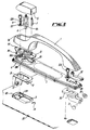
- FIG. 4 shows a modification of the handle assembly shown in Figures 1 to 3.
- parts the same as, or equivalent to, parts of the embodiment of Figures 1 to 3 bear the same reference numerals.
- the shape of the adjustable guide bush 10 is altered as shown and is disposed beneath the handle 1 in which position it is screwed directly to the handle 1 by means of two screws 36 which extend through corresponding apertures 37 in bush 10 into threaded blind bores in the handle 1.
- screw 11 is dispensed with.
- the handle 1 pivots as before about its front end.
- the cooperating parts of the hinge are separate components connected respectively to the handle 1 and base 2.
- foot 32 is silver soldered to handle 1 and bracket 34 is connected initially by a solid rivet 33 to base 2 until assembly when screw 12A also performs to function.
- the pin 3 which extends through the hinge parts 32 and 34 is provided with a head at one end and a lock washer 35 at the other.
- This arrangement enables the handle 1 and base 2 to be forged from brass, the handle 1 by a hot stamping and base 2 by cold. Those intricate parts such as the foot 32 which are difficult if not impossible to forge are made as separate parts. Aperture 1A cannot be formed as before and bearing 10 is therefore attached directly to the underside of the handle 1 as described. Forging in turn enables a higher quality finish to be achieved than would be possible with the die cast parts of the first embodiment.
Landscapes
- Engineering & Computer Science (AREA)
- Mechanical Engineering (AREA)
- Lock And Its Accessories (AREA)
Claims (10)
Applications Claiming Priority (2)
| Application Number | Priority Date | Filing Date | Title |
|---|---|---|---|
| GB8701875 | 1987-01-28 | ||
| GB878701875A GB8701875D0 (en) | 1987-01-28 | 1987-01-28 | Handle assembly |
Publications (3)
| Publication Number | Publication Date |
|---|---|
| EP0276972A2 EP0276972A2 (de) | 1988-08-03 |
| EP0276972A3 EP0276972A3 (en) | 1989-05-24 |
| EP0276972B1 true EP0276972B1 (de) | 1991-12-11 |
Family
ID=10611343
Family Applications (1)
| Application Number | Title | Priority Date | Filing Date |
|---|---|---|---|
| EP88300610A Expired - Lifetime EP0276972B1 (de) | 1987-01-28 | 1988-01-26 | Handhabenzusammenbau |
Country Status (8)
| Country | Link |
|---|---|
| US (1) | US4883296A (de) |
| EP (1) | EP0276972B1 (de) |
| JP (1) | JP2527780B2 (de) |
| KR (1) | KR880008912A (de) |
| AU (1) | AU589830B2 (de) |
| DE (1) | DE3866711D1 (de) |
| ES (1) | ES2029005T3 (de) |
| GB (1) | GB8701875D0 (de) |
Families Citing this family (55)
| Publication number | Priority date | Publication date | Assignee | Title |
|---|---|---|---|---|
| IT1232296B (it) * | 1989-09-22 | 1992-01-28 | Gilardini Spa | Maniglia per portiera di autoveicoli |
| JPH0751571Y2 (ja) * | 1991-06-28 | 1995-11-22 | 株式会社アルファ | アウトサイドドアハンドル装置 |
| ES2051618B1 (es) * | 1992-01-20 | 1997-05-16 | Valeo Clausor S A | Procedimiento para la fabricacion de manecillas huecas para cerraduras de vehiculos y similares. |
| US5176016A (en) * | 1992-03-19 | 1993-01-05 | Hill Mark L | Automobile handle guard plate |
| US5352004A (en) * | 1993-08-26 | 1994-10-04 | Illinois Tool Works Inc. | Gasket rib lock for door handle assembly |
| DE29521920U1 (de) * | 1995-03-04 | 1998-10-22 | Kiekert AG, 42579 Heiligenhaus | Betätigungseinrichtung für das Türschloß einer Kraftfahrzeugtür |
| JP3444721B2 (ja) * | 1996-03-26 | 2003-09-08 | トヨタ自動車株式会社 | 自動車用ドアハンドル |
| JP3689192B2 (ja) * | 1996-08-07 | 2005-08-31 | 本田技研工業株式会社 | 車両のドアグリップ構造 |
| US6038938A (en) * | 1997-10-14 | 2000-03-21 | New Venture Gear, Inc. | Shift fork/gate assembly |
| DE19813316A1 (de) * | 1998-03-26 | 1999-10-07 | Huf Huelsbeck & Fuerst Gmbh | Betätigungsvorrichtung für ein Türschloß mit klappbeweglichem Griff, insbesondere für ein Fahrzeugschloß |
| FR2782535B1 (fr) | 1998-08-19 | 2000-11-10 | Meritor Light Vehicle Sys Ltd | Dispositif de montage de commande d'ouverture de porte de vehicule |
| DE19845395C2 (de) * | 1998-10-02 | 2001-05-10 | Daimler Chrysler Ag | Griffanordnung für eine Fahrzeugtür |
| DE29819472U1 (de) * | 1998-10-31 | 1999-02-18 | Kiekert AG, 42579 Heiligenhaus | Kraftfahrzeugtürverschluß mit Ziehgriff |
| FR2789428B1 (fr) * | 1999-02-05 | 2001-04-13 | Valeo Securite Habitacle | Poignee d'ouvrant de vehicule automobile comportant des moyens perfectionnes de blocage d'un element externe |
| FR2789429B1 (fr) * | 1999-02-05 | 2001-04-13 | Valeo Securite Habitacle | Poignee d'ouvrant de vehicule automobile comportant des moyens perfectionnes de montage d'un levier de prehension |
| FR2789426B1 (fr) * | 1999-02-05 | 2001-06-15 | Valeo Securite Habitacle | Poignee d'ouvrant de vehicule automobile |
| US6240751B1 (en) * | 1999-04-16 | 2001-06-05 | Tri/Mark Corporation | Operator for a latch system |
| US6123386A (en) * | 1999-04-28 | 2000-09-26 | Daimlerchrysler Corporation | Dual action rear gate door handle assembly |
| IT1319905B1 (it) * | 2000-02-23 | 2003-11-12 | Valeo Sicurezza Abitacolo Spa | Maniglia per una portiera di un veicolo. |
| US6612630B1 (en) * | 2000-10-13 | 2003-09-02 | Adac Plastics Inc. | Motor vehicle door handle assembly with split housing |
| JP3569675B2 (ja) * | 2000-12-14 | 2004-09-22 | 株式会社ユーシン | 自動車用ハンドル装置 |
| US6964439B2 (en) * | 2001-01-11 | 2005-11-15 | Aisin Seiki Kabushiki Kaisha | Vehicle door handle device |
| US6896302B2 (en) * | 2001-08-17 | 2005-05-24 | Illinois Tool Works Inc. | Push button release apparatus |
| FR2840939B1 (fr) * | 2002-06-14 | 2005-09-02 | Ferco Int Usine Ferrures | Poignee de manoeuvre pour ouvrant coulissant |
| DE50300798D1 (de) * | 2002-09-20 | 2005-08-25 | Porsche Ag | Schliesseinrichtung für eine Fahrzeugtür |
| KR100462557B1 (ko) * | 2002-11-16 | 2004-12-17 | 기아자동차주식회사 | 자동차용 도어핸들 |
| EP1518981B1 (de) * | 2003-08-29 | 2006-02-08 | Huf Hülsbeck & Fürst GmbH & Co. KG | Türaussengriff |
| CN1878922A (zh) * | 2003-11-03 | 2006-12-13 | 关键塑料有限公司 | 表面突入最小的外部门把手 |
| US7152893B2 (en) * | 2004-08-23 | 2006-12-26 | Key Plastics, Llc | Handle assembly with dual latch feature |
| USD536595S1 (en) * | 2005-02-25 | 2007-02-13 | Toyota Jidosha Kabushiki Kaisha | Door handle for automobile |
| US7568744B2 (en) * | 2005-09-22 | 2009-08-04 | Nissan Technical Center North America, Inc. | Vehicle door handle assembly |
| USD531880S1 (en) * | 2005-10-11 | 2006-11-14 | Yu Lin Enterprise Co., Ltd. | Illuminant door handle for an automobile |
| USD533431S1 (en) * | 2005-10-11 | 2006-12-12 | Yu Lin Enterprise Co., Ltd. | Illuminant door handle for an automobile |
| DE202006003304U1 (de) * | 2006-03-02 | 2007-07-05 | Dirak Dieter Ramsauer Konstruktionselemente Gmbh & Co. Kg | Griff mit Verschlußeinsatz |
| USD587980S1 (en) * | 2006-12-27 | 2009-03-10 | Dr. Ing. H.C. F. Porsche Aktiengesellschaft | Door handle for an automobile |
| USD588436S1 (en) * | 2006-12-27 | 2009-03-17 | Dr. Ing. H.C. F. Porsche Aktiengesellschaft | Door handle assembly |
| US20080211258A1 (en) * | 2007-01-25 | 2008-09-04 | Daniel Edward Jenks | Door handle reinforcement plate |
| USD585719S1 (en) * | 2007-08-28 | 2009-02-03 | Toyota Jidosha Kabushiki Kaisha | Door handle for an automobile |
| JP4903185B2 (ja) * | 2008-08-05 | 2012-03-28 | 本田技研工業株式会社 | アウタハンドルの取付構造 |
| USD629275S1 (en) * | 2008-08-18 | 2010-12-21 | D. la Porte Söhne GmbH | Handle |
| USD610956S1 (en) * | 2008-12-11 | 2010-03-02 | Bayerische Motoren Werke Aktiengesellschaft | Front bumper for a vehicle |
| USD638683S1 (en) * | 2009-03-13 | 2011-05-31 | Alpha Corporation | Door handle for automobile |
| USD621679S1 (en) * | 2009-09-21 | 2010-08-17 | Ford Motor Company | Vehicle door handle set |
| DE102011002287A1 (de) * | 2011-04-27 | 2012-10-31 | Huf Hülsbeck & Fürst Gmbh & Co. Kg | Handhabe mit einem Sicherungselement, dessen Befestigungsmittel vollständig innenseitig eines beweglichen Teils verbleibt |
| USD677143S1 (en) * | 2011-11-02 | 2013-03-05 | Ford Motor Company | Vehicle door handle |
| USD672219S1 (en) * | 2011-11-02 | 2012-12-11 | Ford Global Technologies, Llc | Vehicle door handle |
| CN103132783A (zh) * | 2011-11-26 | 2013-06-05 | 张国网 | 一种汽车右前门内开手柄 |
| CN103132780A (zh) * | 2011-11-26 | 2013-06-05 | 张国网 | 一种汽车左前门内开手柄 |
| US20160010368A1 (en) * | 2013-02-06 | 2016-01-14 | Honda Motor Co., Ltd. | Structure for attaching vehicle door handle device |
| USD708924S1 (en) * | 2013-05-09 | 2014-07-15 | Trimark Corporation | Pull handle with integrated keypad |
| US20150135782A1 (en) * | 2013-11-04 | 2015-05-21 | Hansen International, Inc. | Push button lock |
| DE102013222465A1 (de) * | 2013-11-06 | 2015-05-07 | Volkswagen Aktiengesellschaft | Schließeinrichtung für eine Tür oder Klappe |
| US9382734B2 (en) * | 2013-11-15 | 2016-07-05 | Brose Schliesssysteme Gmbh & Co. Kg | Door handle arrangement |
| DE102015207475A1 (de) * | 2015-04-23 | 2016-10-27 | Volkswagen Aktiengesellschaft | Schließeinrichtung für eine Tür oder Klappe |
| USD985356S1 (en) * | 2021-08-30 | 2023-05-09 | Guangzhou Maike Auto Accessories Co., Ltd. | Car door handle |
Family Cites Families (5)
| Publication number | Priority date | Publication date | Assignee | Title |
|---|---|---|---|---|
| DE1607397U (de) * | 1950-03-27 | 1950-06-01 | Witte & Co Ewald | Tuerschloss insbesondere fuer kraftfahrzeuge. |
| US2739831A (en) * | 1953-01-29 | 1956-03-27 | Keeler Brass Co | Push button door handles adapted for use on the doors of automobiles, refrigerators, and the like |
| US3054634A (en) * | 1960-06-30 | 1962-09-18 | Ford Motor Co | Door handle assembly |
| US3162374A (en) * | 1961-11-24 | 1964-12-22 | Skokut Louis | Illuminating means for the keyhole of door locks |
| IT8020417V0 (it) * | 1980-01-07 | 1980-01-07 | Alfa Romeo Spa | Maniglia esterna per porta di autoveicolo. |
-
1987
- 1987-01-28 GB GB878701875A patent/GB8701875D0/en active Pending
-
1988
- 1988-01-25 US US07/148,019 patent/US4883296A/en not_active Expired - Lifetime
- 1988-01-26 ES ES198888300610T patent/ES2029005T3/es not_active Expired - Lifetime
- 1988-01-26 DE DE8888300610T patent/DE3866711D1/de not_active Expired - Fee Related
- 1988-01-26 EP EP88300610A patent/EP0276972B1/de not_active Expired - Lifetime
- 1988-01-28 KR KR1019880000692A patent/KR880008912A/ko not_active Ceased
- 1988-01-28 AU AU10942/88A patent/AU589830B2/en not_active Ceased
- 1988-01-28 JP JP1847788A patent/JP2527780B2/ja not_active Expired - Lifetime
Also Published As
| Publication number | Publication date |
|---|---|
| KR880008912A (ko) | 1988-09-13 |
| AU1094288A (en) | 1988-08-04 |
| EP0276972A2 (de) | 1988-08-03 |
| DE3866711D1 (de) | 1992-01-23 |
| GB8701875D0 (en) | 1987-03-04 |
| EP0276972A3 (en) | 1989-05-24 |
| ES2029005T3 (es) | 1992-07-16 |
| JP2527780B2 (ja) | 1996-08-28 |
| JPS63297675A (ja) | 1988-12-05 |
| AU589830B2 (en) | 1989-10-19 |
| US4883296A (en) | 1989-11-28 |
Similar Documents
| Publication | Publication Date | Title |
|---|---|---|
| EP0276972B1 (de) | Handhabenzusammenbau | |
| US5377450A (en) | Adjustable door handle assembly | |
| US4441835A (en) | Pivot joints | |
| US5657174A (en) | Mirror assembly having seperate fixed and movable cover members for covering fixed and movable mirror structures respectively | |
| JPS5931633B2 (ja) | 自動車用ドアハンドル装置 | |
| JP2729571B2 (ja) | ドアロック装置 | |
| JPH08193456A (ja) | ドア固定装置と一体構造の自動車ドア用ドア蝶番 | |
| EP0894918B1 (de) | Schliessblech für ein Fahrzeugsschloss | |
| US20030140455A1 (en) | Provisional door-stop device for vehicle doors | |
| DE112010000453B4 (de) | Schaltereingriffsanordnung für eine Fahrzeugtürplatte | |
| US5850673A (en) | Constant contact hinge assembly | |
| US4426858A (en) | Tamper deactivating assembly | |
| US6254150B1 (en) | Locking arrangement for a movable vehicle body part | |
| US5966255A (en) | Escape device for an inner mirror | |
| US4841600A (en) | Door check and stop | |
| US6067874A (en) | Actuating arrangement for a Bowden cable | |
| US5842728A (en) | Impact resistant vehicle door latch device | |
| US3433519A (en) | Automobile door internal handle assembly | |
| US7162775B2 (en) | Boot cover hinge | |
| JP2000008664A (ja) | 車両用ドアアウトサイドハンドル装置 | |
| EP1000788A3 (de) | Mehrteiliges Verschlussteil, insbesondere Fahrzeugtür, mit einem Innenteil aus Leichtmetallguss | |
| EP3665347B1 (de) | Fahrzeugtürgriffanordnung und verfahren zur montage davon | |
| KR200141623Y1 (ko) | 차량용 트렁크리드의 엠블럼커버 | |
| US4527822A (en) | Sunroof latch | |
| DE19809427A1 (de) | Integralteil für eine Fahrzeugtür zur Aufnahme und Halterung von Funktionselementen |
Legal Events
| Date | Code | Title | Description |
|---|---|---|---|
| PUAI | Public reference made under article 153(3) epc to a published international application that has entered the european phase |
Free format text: ORIGINAL CODE: 0009012 |
|
| AK | Designated contracting states |
Kind code of ref document: A2 Designated state(s): CH DE ES FR GB IT LI NL SE |
|
| PUAL | Search report despatched |
Free format text: ORIGINAL CODE: 0009013 |
|
| AK | Designated contracting states |
Kind code of ref document: A3 Designated state(s): CH DE ES FR GB IT LI NL SE |
|
| 17P | Request for examination filed |
Effective date: 19890615 |
|
| 17Q | First examination report despatched |
Effective date: 19900919 |
|
| GRAA | (expected) grant |
Free format text: ORIGINAL CODE: 0009210 |
|
| AK | Designated contracting states |
Kind code of ref document: B1 Designated state(s): CH DE ES FR GB IT LI NL SE |
|
| REF | Corresponds to: |
Ref document number: 3866711 Country of ref document: DE Date of ref document: 19920123 |
|
| ITF | It: translation for a ep patent filed | ||
| ET | Fr: translation filed | ||
| REG | Reference to a national code |
Ref country code: ES Ref legal event code: FG2A Ref document number: 2029005 Country of ref document: ES Kind code of ref document: T3 |
|
| PLBE | No opposition filed within time limit |
Free format text: ORIGINAL CODE: 0009261 |
|
| STAA | Information on the status of an ep patent application or granted ep patent |
Free format text: STATUS: NO OPPOSITION FILED WITHIN TIME LIMIT |
|
| 26N | No opposition filed | ||
| PGFP | Annual fee paid to national office [announced via postgrant information from national office to epo] |
Ref country code: NL Payment date: 19940131 Year of fee payment: 7 |
|
| EAL | Se: european patent in force in sweden |
Ref document number: 88300610.8 |
|
| PG25 | Lapsed in a contracting state [announced via postgrant information from national office to epo] |
Ref country code: NL Effective date: 19950801 |
|
| NLV4 | Nl: lapsed or anulled due to non-payment of the annual fee |
Effective date: 19950801 |
|
| PGFP | Annual fee paid to national office [announced via postgrant information from national office to epo] |
Ref country code: CH Payment date: 20000320 Year of fee payment: 13 |
|
| PGFP | Annual fee paid to national office [announced via postgrant information from national office to epo] |
Ref country code: SE Payment date: 20000321 Year of fee payment: 13 |
|
| PG25 | Lapsed in a contracting state [announced via postgrant information from national office to epo] |
Ref country code: SE Free format text: LAPSE BECAUSE OF NON-PAYMENT OF DUE FEES Effective date: 20010127 |
|
| PG25 | Lapsed in a contracting state [announced via postgrant information from national office to epo] |
Ref country code: CH Free format text: LAPSE BECAUSE OF NON-PAYMENT OF DUE FEES Effective date: 20010131 Ref country code: LI Free format text: LAPSE BECAUSE OF NON-PAYMENT OF DUE FEES Effective date: 20010131 |
|
| EUG | Se: european patent has lapsed |
Ref document number: 88300610.8 |
|
| REG | Reference to a national code |
Ref country code: CH Ref legal event code: PL |
|
| REG | Reference to a national code |
Ref country code: GB Ref legal event code: IF02 |
|
| PGFP | Annual fee paid to national office [announced via postgrant information from national office to epo] |
Ref country code: ES Payment date: 20050113 Year of fee payment: 18 |
|
| PG25 | Lapsed in a contracting state [announced via postgrant information from national office to epo] |
Ref country code: IT Free format text: LAPSE BECAUSE OF NON-PAYMENT OF DUE FEES;WARNING: LAPSES OF ITALIAN PATENTS WITH EFFECTIVE DATE BEFORE 2007 MAY HAVE OCCURRED AT ANY TIME BEFORE 2007. THE CORRECT EFFECTIVE DATE MAY BE DIFFERENT FROM THE ONE RECORDED. Effective date: 20050126 |
|
| PGFP | Annual fee paid to national office [announced via postgrant information from national office to epo] |
Ref country code: DE Payment date: 20050127 Year of fee payment: 18 |
|
| PGFP | Annual fee paid to national office [announced via postgrant information from national office to epo] |
Ref country code: GB Payment date: 20060109 Year of fee payment: 19 |
|
| PG25 | Lapsed in a contracting state [announced via postgrant information from national office to epo] |
Ref country code: ES Free format text: LAPSE BECAUSE OF NON-PAYMENT OF DUE FEES Effective date: 20060127 |
|
| PGFP | Annual fee paid to national office [announced via postgrant information from national office to epo] |
Ref country code: FR Payment date: 20060127 Year of fee payment: 19 |
|
| PG25 | Lapsed in a contracting state [announced via postgrant information from national office to epo] |
Ref country code: DE Free format text: LAPSE BECAUSE OF NON-PAYMENT OF DUE FEES Effective date: 20060801 |
|
| REG | Reference to a national code |
Ref country code: ES Ref legal event code: FD2A Effective date: 20060127 |
|
| GBPC | Gb: european patent ceased through non-payment of renewal fee |
Effective date: 20070126 |
|
| REG | Reference to a national code |
Ref country code: FR Ref legal event code: ST Effective date: 20070930 |
|
| PG25 | Lapsed in a contracting state [announced via postgrant information from national office to epo] |
Ref country code: GB Free format text: LAPSE BECAUSE OF NON-PAYMENT OF DUE FEES Effective date: 20070126 |
|
| PG25 | Lapsed in a contracting state [announced via postgrant information from national office to epo] |
Ref country code: FR Free format text: LAPSE BECAUSE OF NON-PAYMENT OF DUE FEES Effective date: 20070131 |