EP0276458B1 - Device for adding water for steam generation into a cooking appliance - Google Patents
Device for adding water for steam generation into a cooking appliance Download PDFInfo
- Publication number
- EP0276458B1 EP0276458B1 EP87118906A EP87118906A EP0276458B1 EP 0276458 B1 EP0276458 B1 EP 0276458B1 EP 87118906 A EP87118906 A EP 87118906A EP 87118906 A EP87118906 A EP 87118906A EP 0276458 B1 EP0276458 B1 EP 0276458B1
- Authority
- EP
- European Patent Office
- Prior art keywords
- container
- water
- drawer
- control disc
- follower pin
- Prior art date
- Legal status (The legal status is an assumption and is not a legal conclusion. Google has not performed a legal analysis and makes no representation as to the accuracy of the status listed.)
- Expired - Lifetime
Links
Images


Classifications
-
- F—MECHANICAL ENGINEERING; LIGHTING; HEATING; WEAPONS; BLASTING
- F24—HEATING; RANGES; VENTILATING
- F24C—DOMESTIC STOVES OR RANGES ; DETAILS OF DOMESTIC STOVES OR RANGES, OF GENERAL APPLICATION
- F24C15/00—Details
- F24C15/32—Arrangements of ducts for hot gases, e.g. in or around baking ovens
- F24C15/322—Arrangements of ducts for hot gases, e.g. in or around baking ovens with forced circulation
- F24C15/327—Arrangements of ducts for hot gases, e.g. in or around baking ovens with forced circulation with air moisturising
Definitions
- the invention relates to a device for adding water to generate steam in a cooking device.
- DE-A-16 79 196 describes a kitchen stove which is suitable for cooking with steam in the oven and the muffle bottom of which has a trough-like depression for receiving the water to be evaporated.
- the water can obviously only be added by opening the loading door and pouring from a vessel into the trough-like depression.
- this is an unsatisfactory option for operating the cooker.
- some cooking and baked goods are treated much better by steam, today even in fitted kitchens with built-in ovens in the surrounding cupboards and optionally with a built-in hob, in addition to the optional switching on of the radiators for top and / or bottom heat and possibly one Hot air circulation fan, a possibility of steam generation is provided.
- the object of the invention is to simplify the addition of water to such cooking devices.
- Water can be conveniently added to the cooking space or an evaporation vessel via the vessel designed as a drawer in the area of the control panel. This process can also be triggered automatically by a timer at a specified time.
- the housing 2 surrounding the oven muffle 1 of a built-in oven according to FIG. 1 is only indicated schematically.
- a pot-like evaporation vessel 4 is inserted, which is connected to a water supply line 5.
- the water supply line 5 starts from a water filling container designed as a drawer 6, which is arranged in the area of the control panel 7 above the loading door 8. It is no problem for the housewife to pull the drawer 6 outwards and fill in the required amount of water.
- the filled water flows into the evaporation tank 4 via the elastic water supply line 5 and is evaporated there by an electric heater.
- the usual vapor outlet opening 9 should e.g. be closed by a slide.
- the water filling container which is designed as a drawer, with a quick coupling at the connection point to the water supply line 5, which in the uncoupled state prevents the water spout but releases it in the coupled state.
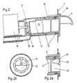
- FIG. 2 An embodiment for automatically emptying the drawer at a predetermined point in time is shown in FIG. 2.
- the container 10 is provided as a drawer, which can be inserted into the guide part 12 of the device housing provided for this purpose by means of the front handle 11.
- the container 10 can be rotated about its longitudinal axis within the guide part 12 and is therefore cylindrical and guided by spacing cams 13.
- An upper emptying or emptying cutout 14 in the container housing enables water to be poured into the container 10 pulled out of the device. Through the same cutout, when the container 10 rotates when the device is operating, the water escapes into the cooking space via a drain line 15.
- the rotation of the container at the desired time is effected by a control disk 17 driven by a clockwork 16, with which the container 10 can be coupled via a driving pin 18.
- the mode of operation is shown in FIG. 3.
- the arrow A is the zero mark on the control panel 7.
- the schematically indicated control disk 17 has a pair of adjusting cams 19 and a driving cam 20 in the effective range of which the driving pin 18 of the container 2 is located when it is pushed into the device.
- 3e and 3f show the movements of the parts belonging to one another at a setting of 20 minutes.
- FIGS. 2a + 2b a special handle design is shown in FIGS. 2a + 2b.
- the cylindrical, water-absorbing middle part 21 of the container 10 is preceded by a chamber 22, which is covered by the front half wall part 23.
- a handle web 24 crossing the chamber, which extends from the front wall part 23 to the central part 21, facilitates the rotation of the container for winding up the clockwork.
Abstract
Description
Die Erfindung betrifft eine Vorrichtung zum Zugeben von Wasser zur Dampferzeugung in ein Gargerät.The invention relates to a device for adding water to generate steam in a cooking device.
Für die optimale Behandlung von Speisen ist es oftmals zweckmäßig in dem Garraum eines Gargerätes, z. B. in der Muffel eines Herdes, zu einer bestimmten Zeit während des Garvorganges eine wasserdampf-gesättigte Atmosphäre zu erzeugen. Man kann hierzu in den heißen Garraum Wasser geben, das dann verdampft und den gewünschten Zweck bewirkt.For the optimal treatment of food, it is often useful in the cooking space of a cooking device, e.g. B. in the muffle of a stove to generate a steam-saturated atmosphere at a certain time during the cooking process. To do this, you can add water to the hot cooking space, which then evaporates and has the desired purpose.
In der DE-A-16 79 196 ist ein Küchenherd beschrieben,welcher zum Kochen mit Dampf im Backofen geeignet ist und dessen Muffelboden eine muldenartige Vertiefung zur Aufnahme des zu verdampfenden Wassers aufweist. Über die Art und Weise der Wasserzugabe fehlt jeglicher Hinweis. Das Wasser kann offensichtlich nur durch öffnen der Beschickungstür und Eingießen aus einem Gefäß in die muldenartige Vertiefung zugegeben werden.
Dies ist aber für die Bedienung des Herdes eine unbefriedigende Möglichkeit. Weil manches Gar- und Backgut durch Wasserdampf wesentlich besser behandelt wird, wird heute auch bei Einbauküchen mit in die sie umgebenden Schränke eingebauten und gegebenenfalls mit einer Einbau-Kochmulde ergänzten Einbaubacköfen neben der wahlweise Einschaltung der Heizkörper für Ober- und/ oder Unterhitze und gegebenenfalls eines Heißluftumwälzgebläses, eine Möglichkeit der Dampferzeugung vorgesehen. Es gibt auch Geräte, welche mit zirkulierendem Wasserdampf betrieben werden, aber dabei handelt es sich um Spezialgeräte und nicht um einen üblichen Einbaubackofen für Haushaltsküchen.DE-A-16 79 196 describes a kitchen stove which is suitable for cooking with steam in the oven and the muffle bottom of which has a trough-like depression for receiving the water to be evaporated. There is no information about the way of adding water. The water can obviously only be added by opening the loading door and pouring from a vessel into the trough-like depression.
However, this is an unsatisfactory option for operating the cooker. Because some cooking and baked goods are treated much better by steam, today even in fitted kitchens with built-in ovens in the surrounding cupboards and optionally with a built-in hob, in addition to the optional switching on of the radiators for top and / or bottom heat and possibly one Hot air circulation fan, a possibility of steam generation is provided. There are also devices with circulating Steam operated, but these are special appliances and not a conventional built-in oven for household kitchens.
Aufgabe der Erfindung ist es, die Wasserzugabe bei derartigen Gargeräten zu vereinfachen.The object of the invention is to simplify the addition of water to such cooking devices.
Zur Lösung dieser Aufgabe werden die im Patentanspruch 1 angegebenen Merkmale vorgeschlagen.To achieve this object, the features specified in
Über das als Schublade ausgebildete Gefäß im Bereich der Bedienungsblende kann bequem Wasser dem Garraum oder einem Verdampfungsgefäß zugegeben werden. Dieser Vorgang läßt sich auch durch eine Zeitschaltuhr zu einem vorgegebenen Zeitpunkt automatisch auslösen.Water can be conveniently added to the cooking space or an evaporation vessel via the vessel designed as a drawer in the area of the control panel. This process can also be triggered automatically by a timer at a specified time.
In der Zeichnung sind Ausführungsbeispiele der Erfindung dargestellt. Es zeigen:
- Fig. 1
- einen Einbaubackofen mit einer Schublade als Wassereinfüllgefäß,
- Fig. 2
- den Längsschnitt durch einen drehbaren Behälter für die Wasserzugabe in einer mit einer Steuerscheibe gekoppelten Stellung,
- Fig. 2a + 2b
- eine andere Gestaltung der Griffpartie des Behälters,
- Fig. 3a - 3d
- Funktionsablauf mit einer Zeitvorgabe von 5 min.
- Fig. 3e + 3f
- Funktionsablauf mit einer Zeitvorgabe von 20 min.,
- Fig. 3g + 3h
- Funktionsablauf mit einer Zeitvorgabe von 70 min.
- Fig. 1
- a built-in oven with a drawer as a water filling vessel,
- Fig. 2
- the longitudinal section through a rotatable container for adding water in a position coupled to a control disc,
- 2a + 2b
- a different design of the handle section of the container,
- 3a-3d
- Functional sequence with a time specification of 5 min.
- 3e + 3f
- Function sequence with a time specification of 20 min.,
- 3g + 3h
- Functional sequence with a time specification of 70 min.
Das die Backofenmuffel 1 umgebende Gehäuse 2 eines Einbaubackofens nach Fig. 1 ist nur schematisch angedeutet.The
In den Boden 3 der Backofenmuffel ist ein topfartiges Verdampfungsgefäß 4 eingesetzt, welches an eine Wasserzuführungsleitung 5 angeschlossen ist.In the
Die Wasserzuführungsleitung 5 geht von einem als Schublade 6 ausgebildeten Wassereinfüllbehälter aus, welcher im Bereich der Bedienungsblende 7 oberhalb der Beschickungstür 8 angeordnet ist. Für die Hausfrau ist es kein Problem, die Schublade 6 nach außen vorzuziehen und die benötigte Wassermenge einzufüllen. Über die elastische Wasserzuführungsleitung 5 fließt das eingefüllte Wasser in den Verdampfungsbehälter 4 und wird dort durch eine elektrische Heizung zum Verdampfen gebracht. Bei Dämpfbetrieb sollte die übliche Wrasenaustrittsöffnung 9 z.B. durch einen Schieber verschließbar sein.The
Es ist auch denkbar, den als Schublade ausgebildeten Wassereinfüllbehälter an der Verbindungsstelle zur Wasserzuführungsleitung 5 mit einer Schnellkupplung zu versehen, die im entkuppelten Zustand den Wasserauslauf verhindert ihn im eingekuppelten Zustand aber freigibt.It is also conceivable to provide the water filling container, which is designed as a drawer, with a quick coupling at the connection point to the
Eine Ausführung zum automatischen Entleeren der Schublade zu einem vorgegebenen Zeitpunkt zeigt Fig. 2.An embodiment for automatically emptying the drawer at a predetermined point in time is shown in FIG. 2.
Im vorderen Bereich des nicht dargestellten Gargerätes, im Bereich der Bedienungsblende 7 ist der als Schublade ausgebildete Behälter 10 vorgesehen, welcher mittels des vorderen Griffes 11 in den dafür vorgesehenen Führungsteil 12 des Gerätegehäuses eingeschoben werden kann. Der Behälter 10 ist innerhalb des Führungsteiles 12 um seine Längsachse drehbar und deshalb zylinderförmig ausgebildet und durch Abstandnocken 13 geführt. Ein oberer Ein- bzw. Entleerungsausschnitt 14 im Behältergehäuse ermöglicht das Einfüllen von Wasser in den aus dem Gerät herausgezogenen Behälter 10. Durch denselben Ausschnitt entweicht bei Drehung des Behälters 10 bei Betrieb der Vorrichtung das Wasser über eine Ablaufleitung 15 in den Garraum. Die Drehung des Behälters zu der gewünschten Zeit wird durch eine von einem Uhrwerk 16 angetriebene Steuerscheibe 17 bewirkt, mit welcher der Behälter 10 über einen Mitnahmestift 18 gekoppelt werden kann.In the front area of the cooking device, not shown, in the area of the
In der Fig. 3 ist die Funktionsweise dargestellt. Der Pfeil A ist die Null-Markierung auf der Bedienungsblende 7. Auf der Bedienungsblende ist außerdem eine Zeitskala T angebracht, mit welcher die auf dem Behälter an dessen Vorderseite angebrachte Ausgangs-Stellungs-Markierung B zur Voreinstellung des Uhrwerkes in Übereinstimmung gebracht werden muß. Die schematisch angedeutete Steuerscheibe 17 besitzt ein Einstellnockenpaar 19 sowie einen Mitnahmenocken 20 in deren Wirkungsbereich sich der Mitnahmestift 18 des Behälters 2 befindet, wenn dieser in das Gerät eingeschoben ist.The mode of operation is shown in FIG. 3. The arrow A is the zero mark on the
-
a) Der leere Behälter wird in Ausgangsstellung in das Gerät eingeschoben. Pfeil A und Pfeil B stehen sich einander gegenüber. Der Mitnahmestift 18 schiebt sich dabei zwischen das Einstellnockenpaar 19.a) The empty container is pushed into the device in the starting position. Arrow A and arrow B face each other. The driving
pin 18 slides between the pair of adjustingcams 19. -
b) Der Behälter 10 wird mittels des Griffes 11 jetzt im Uhrzeigersinn so lange gedreht, bis der Pfeil B auf die gewünschte Einstellzeit der Zeitskala T zeigt (Im Beispiel 5 min.). Dabei nimmt der Mitnahmestift 18 die Steuerscheibe 17 mit und das Uhrwerk wird entsprechend aufgezogen.b) The
container 10 is now rotated clockwise by means of thehandle 11 until the arrow B points to the desired setting time of the time scale T (in the example 5 minutes). Thedrive pin 18 takes thecontrol disk 17 and the clockwork is wound accordingly. -
c) Der Behälter 10 wird aus dem Gerät entnommen und Wasser eingefüllt. Die Steuerscheibe 17 verbleibt während der kurzen Zeit des Füllens in der Stellung b).
Der mit Wasser gefüllte Behälter wird in Ausgangsstellung (Pfeile A+B stehen einander gegenüber) wieder eingeschoben. Der Mitnahmestift 18 wird durch den Mitnahmenocken 20 der im Gegenuhrzeigersinn jetzt zurücklaufenden Steuerscheibe 17 nach Ablauf der vorgegebenen Zeit (5 min.) erfaßt und der Behälter mit dem weiteren Rücklauf der Steuerscheibe gedreht. Dadurch wird das sich im Behälter befindende Wasser über den Entleerungsausschnitt 12 ausgekippt und es gelangt über die entsprechende Ablaufleitung 15 in den Garraum.c) Thecontainer 10 is removed from the device and water is filled. Thecontrol disk 17 remains in the position b) during the short time of filling.
The container filled with water is pushed back into the starting position (arrows A + B are opposite each other). The drivingpin 18 is gripped by the drivingcam 20 of thecontrol disk 17 now running counterclockwise after the specified time (5 minutes) and the container is rotated with the further return of the control disk. As a result, the water in the container is tipped over the emptyingcutout 12 and it reaches the cooking chamber via thecorresponding drain line 15. - d) Nach Rücklauf der Steuerscheibe und Drehung des Behälters befindet sich die Steuerscheibe wieder in der Ausgangsstellung und es kann erneut Wasser zugegeben werden.d) After the control disc has returned and the container has rotated, the control disc is again in the starting position and water can be added again.
Die Fig. 3e und 3f zeigen die Bewegungen der zueinander gehörenden Teile bei einer Einstellung von 20 min. Vorlaufzeit und die Fig. 3g und 3h bei 70 min. Vorlaufzeit. Bei dem Ausführungsbeispiel sind 5 min. die geringst mögliche Aufzugzeit und 70 min. der maximal mögliche Aufzug.3e and 3f show the movements of the parts belonging to one another at a setting of 20 minutes. Lead time and Fig. 3g and 3h at 70 min. Lead time. In which Embodiment are 5 min. the lowest possible elevator time and 70 min. the maximum possible elevator.
Um möglichst aus dem Gerät vorstehende Teile zu vermeiden ist in den Fig. 2a + 2b eine spezielle Griffgestaltung dargestellt. Dem zylindrischen, das Wasser aufnehmende Mittelteil 21 des Behälters 10 ist eine Kammer 22 vorgeschaltet, welche durch den vorderen halben Wandteil 23 abgedeckt ist. Ein die Kammer durchquerender Griffsteg 24, welcher sich von dem vorderen Wandteil 23 bis zum Mittelteil 21 erstreckt erleichtert das Drehen des Behälters zum Aufziehen des Uhrwerkes.In order to avoid parts protruding from the device as far as possible, a special handle design is shown in FIGS. 2a + 2b. The cylindrical, water-absorbing
Claims (12)
- Device for adding water for steam generation in a cooking device, in particular for a cooker having an oven with electric heating and hot-air circulation, characterised in that the water is supplied from a water container which is provided in the vicinity of the operational armature and is formed as a drawer (6).
- Device according to claim 1, characterised in that the drawer (6) is constructed as tank which can be removed from the device and can be connected to the water supply line (5) by means of quick coupling.
- Device according to claims 1 and/or 2, characterised in that the drawer is constructed as container (10) which can rotate about its longitudinal axis and can be coupled to a rotating control disc (17) of a clockwork mechanism.
- Device according to claim 3, characterised in that the container comprises a cylindrical central part (21) which accommodates the water and is provided at its rear upper area with a filling and/or emptying section (12).
- Device according to any one of claims 1 to 4, characterised in that the container (10) comprises on its front face a handle (11) and a marking (B) which defines the initial position.
- Device according to claim 5, characterised in that the handle consists of one wall part (23) which covers approximately half of the front face of a chamber (22) which is disposed in front of the cylindrical central part (21), and that behind this wall part there is provided a handle bar (24) which traverses the chamber (22) in the longitudinal direction.
- Device according to claim 6, characterised in that the handle bar (24) is formed as an intermediate wall which traverses the chamber (22) axially in the radial direction from the front half wall part to the central part (21).
- Device according to any one of claims 1 to 7, characterised in that the container (10) is provided at its rear end with a follower pin (18) which engages in the area of drive elements of the control disc (17) which itself is driven by clockwork when the container (10) is inserted.
- Device according to claim 8, characterised in that the follower pin (18) serves for winding up the clockwork mechanism (16) of the control disc (17) when the container (10) is empty.
- Device according to any one of claims 3 to 9, characterised in that the control disc (17) comprises a pair of control cams (19) which engage the follower pin (18) on both sides and also a drive cam (20).
- Device according to claim 10, characterised in that, when the control disc (17) is in the zero position and the container (10) in its initial position, the position of the follower pin (18) coincides with the position of the control cam pair (19).
- Device according to claim 11, characterised in that in the zero position the pair of control cams (19) are displaced by 180° and opposite the marking (B) of the initial position of the container (10).
Priority Applications (1)
| Application Number | Priority Date | Filing Date | Title |
|---|---|---|---|
| AT87118906T ATE67579T1 (en) | 1987-01-28 | 1987-12-19 | DEVICE FOR ADDING WATER TO GENERATE STEAM INTO A COOKING APPLIANCE. |
Applications Claiming Priority (4)
| Application Number | Priority Date | Filing Date | Title |
|---|---|---|---|
| DE19873702455 DE3702455A1 (en) | 1987-01-28 | 1987-01-28 | Device for automatically adding water for steam generation to cooking apparatus |
| DE3702455 | 1987-01-28 | ||
| DE19873703857 DE3703857A1 (en) | 1987-02-07 | 1987-02-07 | Cooker with electric heating of the oven |
| DE3703857 | 1987-02-07 |
Publications (3)
| Publication Number | Publication Date |
|---|---|
| EP0276458A2 EP0276458A2 (en) | 1988-08-03 |
| EP0276458A3 EP0276458A3 (en) | 1989-11-02 |
| EP0276458B1 true EP0276458B1 (en) | 1991-09-18 |
Family
ID=25851943
Family Applications (1)
| Application Number | Title | Priority Date | Filing Date |
|---|---|---|---|
| EP87118906A Expired - Lifetime EP0276458B1 (en) | 1987-01-28 | 1987-12-19 | Device for adding water for steam generation into a cooking appliance |
Country Status (3)
| Country | Link |
|---|---|
| EP (1) | EP0276458B1 (en) |
| AT (1) | ATE67579T1 (en) |
| DE (1) | DE3773172D1 (en) |
Cited By (2)
| Publication number | Priority date | Publication date | Assignee | Title |
|---|---|---|---|---|
| US8196439B2 (en) * | 2007-05-02 | 2012-06-12 | Lg Electronics Inc. | Laundry machine including a support module with a drawer based detachable water supply |
| KR20200012310A (en) * | 2018-07-26 | 2020-02-05 | 엘지전자 주식회사 | Cooking appliance |
Families Citing this family (13)
| Publication number | Priority date | Publication date | Assignee | Title |
|---|---|---|---|---|
| DE4427460C2 (en) * | 1994-08-03 | 1997-07-10 | Bosch Siemens Hausgeraete | Oven for steaming |
| FR2814734B1 (en) * | 2000-10-02 | 2003-01-17 | Brandt Cooking | REMOVABLE WATER TANK, ESPECIALLY FOR A STEAM COOKING OVEN |
| KR101041071B1 (en) * | 2003-12-30 | 2011-06-13 | 삼성전자주식회사 | Heating cooker |
| JP2006038316A (en) | 2004-07-26 | 2006-02-09 | Toshiba Corp | Heating cooker |
| FR2887966B1 (en) * | 2005-07-01 | 2007-08-17 | Seb Sa | OVEN COMPRISING A DEVICE FOR EVAPORATING WATER |
| FR2887967B1 (en) * | 2005-07-01 | 2007-08-17 | Seb Sa | DEVICE FOR EVAPORATING WATER |
| KR101203840B1 (en) * | 2006-12-14 | 2012-11-21 | 엘지전자 주식회사 | laundry device and control method of the same |
| DE102010063203A1 (en) * | 2010-12-16 | 2012-06-21 | BSH Bosch und Siemens Hausgeräte GmbH | Device for a domestic appliance, with a container for a liquid or powdery medium |
| EP2522915B1 (en) * | 2011-05-13 | 2015-02-18 | Electrolux Home Products Corporation N.V. | Appliance, especially domestic appliance |
| CN105455660B (en) * | 2016-01-25 | 2017-10-03 | 宁波方太厨具有限公司 | A kind of upper turning mechanism of control panel and application have the steam box of turning mechanism on this |
| SI25270A (en) * | 2016-09-16 | 2018-03-30 | Gorenje Gospodinjski Aparati, D.D. | The button assembly |
| CN219594381U (en) * | 2022-02-18 | 2023-08-29 | 新美格股份有限公司 | Oven for cooking food |
| KR20240018307A (en) * | 2022-08-02 | 2024-02-13 | 엘지전자 주식회사 | Cooking appliance |
Family Cites Families (1)
| Publication number | Priority date | Publication date | Assignee | Title |
|---|---|---|---|---|
| DE1679196A1 (en) * | 1967-04-27 | 1971-04-08 | Frank Sche Eisenwerke Ag | Kitchen stove |
-
1987
- 1987-12-19 DE DE8787118906T patent/DE3773172D1/en not_active Expired - Lifetime
- 1987-12-19 EP EP87118906A patent/EP0276458B1/en not_active Expired - Lifetime
- 1987-12-19 AT AT87118906T patent/ATE67579T1/en not_active IP Right Cessation
Cited By (5)
| Publication number | Priority date | Publication date | Assignee | Title |
|---|---|---|---|---|
| US8196439B2 (en) * | 2007-05-02 | 2012-06-12 | Lg Electronics Inc. | Laundry machine including a support module with a drawer based detachable water supply |
| KR20200012310A (en) * | 2018-07-26 | 2020-02-05 | 엘지전자 주식회사 | Cooking appliance |
| KR20230048483A (en) * | 2018-07-26 | 2023-04-11 | 엘지전자 주식회사 | Cooking appliance |
| KR102564246B1 (en) | 2018-07-26 | 2023-08-07 | 엘지전자 주식회사 | Cooking appliance |
| KR102642751B1 (en) | 2018-07-26 | 2024-02-29 | 엘지전자 주식회사 | Cooking appliance |
Also Published As
| Publication number | Publication date |
|---|---|
| EP0276458A2 (en) | 1988-08-03 |
| EP0276458A3 (en) | 1989-11-02 |
| DE3773172D1 (en) | 1991-10-24 |
| ATE67579T1 (en) | 1991-10-15 |
Similar Documents
| Publication | Publication Date | Title |
|---|---|---|
| EP0276458B1 (en) | Device for adding water for steam generation into a cooking appliance | |
| EP0277337A2 (en) | Cooking appliance with electric heating of a cooking room and method of runing such a cooking appliance | |
| DE69916175T2 (en) | cooker | |
| DE3228220C2 (en) | Combination microwave oven with a gas sensor | |
| DE859597C (en) | Washing machine, especially for the household | |
| DE3443477A1 (en) | METHOD AND DEVICE FOR OPERATING AN OPERATION WITH A CIRCULATED HOT AIR OR WATER STEAM | |
| DE3931217A1 (en) | ELECTRICAL DEVICE WITH A TURNTABLE | |
| DE3506082A1 (en) | COOKER | |
| DE3314055A1 (en) | Microwave oven | |
| EP0768055B1 (en) | Baking oven for steam cooking | |
| DE60214214T2 (en) | DEVICE AND METHOD FOR COOKING FOODS WITH MICROWAVES | |
| EP0695503B1 (en) | Oven for steam-cooking | |
| EP1862099A2 (en) | Kitchen appliance with steam unit and retractable heating device | |
| DE2657929B2 (en) | Oven, in particular with means for pyrolytic self-cleaning | |
| DE3221433A1 (en) | Electric deep fat fryer | |
| DE102009001739B3 (en) | Steam cooking device, has control unit heated to specific temperature and heating unit, which generates hot air, is reduced in power or switched off during steam generation, where steam generation takes place in operating mode of device | |
| DE3843039A1 (en) | Domestic appliance | |
| DE3702455A1 (en) | Device for automatically adding water for steam generation to cooking apparatus | |
| CH654193A5 (en) | Table-top oven device | |
| DE2502955C3 (en) | Device for the heat treatment of food | |
| DE3717224C2 (en) | ||
| WO2021197797A1 (en) | Domestic steam treatment appliance and method for cleaning a vaporizer | |
| DE3703857A1 (en) | Cooker with electric heating of the oven | |
| DE3630313C2 (en) | ||
| DE1679045B1 (en) | Electric egg boiling machine |
Legal Events
| Date | Code | Title | Description |
|---|---|---|---|
| PUAI | Public reference made under article 153(3) epc to a published international application that has entered the european phase |
Free format text: ORIGINAL CODE: 0009012 |
|
| AK | Designated contracting states |
Kind code of ref document: A2 Designated state(s): AT BE CH DE FR GB IT LI NL |
|
| PUAL | Search report despatched |
Free format text: ORIGINAL CODE: 0009013 |
|
| AK | Designated contracting states |
Kind code of ref document: A3 Designated state(s): AT BE CH DE FR GB IT LI NL |
|
| 17P | Request for examination filed |
Effective date: 19891201 |
|
| 17Q | First examination report despatched |
Effective date: 19900913 |
|
| GRAA | (expected) grant |
Free format text: ORIGINAL CODE: 0009210 |
|
| STAA | Information on the status of an ep patent application or granted ep patent |
Free format text: STATUS: THE PATENT HAS BEEN GRANTED |
|
| RAP1 | Party data changed (applicant data changed or rights of an application transferred) |
Owner name: ELECTROLUX-JUNO KUECHENTECHNIK GMBH |
|
| AK | Designated contracting states |
Kind code of ref document: B1 Designated state(s): AT BE CH DE FR GB IT LI NL |
|
| REF | Corresponds to: |
Ref document number: 67579 Country of ref document: AT Date of ref document: 19911015 Kind code of ref document: T |
|
| REF | Corresponds to: |
Ref document number: 3773172 Country of ref document: DE Date of ref document: 19911024 |
|
| ITF | It: translation for a ep patent filed |
Owner name: PROPRIA PROTEZIONE PROPR. IND. |
|
| GBT | Gb: translation of ep patent filed (gb section 77(6)(a)/1977) | ||
| PGFP | Annual fee paid to national office [announced via postgrant information from national office to epo] |
Ref country code: NL Payment date: 19911231 Year of fee payment: 5 |
|
| ET | Fr: translation filed | ||
| PGFP | Annual fee paid to national office [announced via postgrant information from national office to epo] |
Ref country code: BE Payment date: 19920107 Year of fee payment: 5 |
|
| PLBE | No opposition filed within time limit |
Free format text: ORIGINAL CODE: 0009261 |
|
| 26N | No opposition filed | ||
| PGFP | Annual fee paid to national office [announced via postgrant information from national office to epo] |
Ref country code: GB Payment date: 19921202 Year of fee payment: 6 |
|
| PGFP | Annual fee paid to national office [announced via postgrant information from national office to epo] |
Ref country code: AT Payment date: 19921229 Year of fee payment: 6 |
|
| PG25 | Lapsed in a contracting state [announced via postgrant information from national office to epo] |
Ref country code: BE Effective date: 19921231 |
|
| BERE | Be: lapsed |
Owner name: ELECTROLUX-JUNO KUCHENTECHNIK G.M.B.H. Effective date: 19921231 |
|
| PG25 | Lapsed in a contracting state [announced via postgrant information from national office to epo] |
Ref country code: NL Effective date: 19930701 |
|
| NLV4 | Nl: lapsed or anulled due to non-payment of the annual fee | ||
| PG25 | Lapsed in a contracting state [announced via postgrant information from national office to epo] |
Ref country code: GB Effective date: 19931219 Ref country code: AT Effective date: 19931219 |
|
| GBPC | Gb: european patent ceased through non-payment of renewal fee |
Effective date: 19931219 |
|
| PGFP | Annual fee paid to national office [announced via postgrant information from national office to epo] |
Ref country code: FR Payment date: 19941216 Year of fee payment: 8 |
|
| PG25 | Lapsed in a contracting state [announced via postgrant information from national office to epo] |
Ref country code: FR Effective date: 19960830 |
|
| REG | Reference to a national code |
Ref country code: FR Ref legal event code: ST |
|
| PGFP | Annual fee paid to national office [announced via postgrant information from national office to epo] |
Ref country code: CH Payment date: 19961220 Year of fee payment: 10 |
|
| PG25 | Lapsed in a contracting state [announced via postgrant information from national office to epo] |
Ref country code: LI Free format text: LAPSE BECAUSE OF NON-PAYMENT OF DUE FEES Effective date: 19971231 Ref country code: CH Free format text: LAPSE BECAUSE OF NON-PAYMENT OF DUE FEES Effective date: 19971231 |
|
| REG | Reference to a national code |
Ref country code: CH Ref legal event code: PL |
|
| PGFP | Annual fee paid to national office [announced via postgrant information from national office to epo] |
Ref country code: DE Payment date: 20010112 Year of fee payment: 14 |
|
| PG25 | Lapsed in a contracting state [announced via postgrant information from national office to epo] |
Ref country code: DE Free format text: LAPSE BECAUSE OF NON-PAYMENT OF DUE FEES Effective date: 20020702 |
|
| PG25 | Lapsed in a contracting state [announced via postgrant information from national office to epo] |
Ref country code: IT Free format text: LAPSE BECAUSE OF NON-PAYMENT OF DUE FEES Effective date: 20051219 |