EP0271775B1 - Hypodermische Vorrichtung aus einem Polymer - Google Patents
Hypodermische Vorrichtung aus einem Polymer Download PDFInfo
- Publication number
- EP0271775B1 EP0271775B1 EP87117844A EP87117844A EP0271775B1 EP 0271775 B1 EP0271775 B1 EP 0271775B1 EP 87117844 A EP87117844 A EP 87117844A EP 87117844 A EP87117844 A EP 87117844A EP 0271775 B1 EP0271775 B1 EP 0271775B1
- Authority
- EP
- European Patent Office
- Prior art keywords
- needle
- injection
- portals
- fluid
- injected
- Prior art date
- Legal status (The legal status is an assumption and is not a legal conclusion. Google has not performed a legal analysis and makes no representation as to the accuracy of the status listed.)
- Expired
Links
- 238000002347 injection Methods 0.000 claims description 47
- 239000007924 injection Substances 0.000 claims description 47
- 239000012530 fluid Substances 0.000 claims description 36
- 239000000463 material Substances 0.000 claims description 14
- 230000000149 penetrating effect Effects 0.000 claims description 5
- 229920000728 polyester Polymers 0.000 claims description 4
- 239000004417 polycarbonate Substances 0.000 claims description 3
- 229920000515 polycarbonate Polymers 0.000 claims description 3
- 239000007787 solid Substances 0.000 claims description 3
- OMIHGPLIXGGMJB-UHFFFAOYSA-N 7-oxabicyclo[4.1.0]hepta-1,3,5-triene Chemical class C1=CC=C2OC2=C1 OMIHGPLIXGGMJB-UHFFFAOYSA-N 0.000 claims description 2
- 239000004696 Poly ether ether ketone Substances 0.000 claims description 2
- 239000004952 Polyamide Substances 0.000 claims description 2
- 150000001252 acrylic acid derivatives Chemical class 0.000 claims description 2
- 229920003235 aromatic polyamide Polymers 0.000 claims description 2
- 229920002492 poly(sulfone) Polymers 0.000 claims description 2
- 229920002647 polyamide Polymers 0.000 claims description 2
- 229920002530 polyetherether ketone Polymers 0.000 claims description 2
- 229920001601 polyetherimide Polymers 0.000 claims description 2
- 229920000306 polymethylpentene Polymers 0.000 claims description 2
- 210000001519 tissue Anatomy 0.000 description 28
- 229920000642 polymer Polymers 0.000 description 19
- 238000000034 method Methods 0.000 description 14
- 238000005520 cutting process Methods 0.000 description 9
- 208000014674 injury Diseases 0.000 description 9
- 238000000465 moulding Methods 0.000 description 8
- 230000008733 trauma Effects 0.000 description 8
- 210000003462 vein Anatomy 0.000 description 8
- 229910000831 Steel Inorganic materials 0.000 description 7
- 210000004369 blood Anatomy 0.000 description 7
- 239000008280 blood Substances 0.000 description 7
- 230000035515 penetration Effects 0.000 description 7
- 239000010959 steel Substances 0.000 description 7
- 230000006378 damage Effects 0.000 description 6
- 239000000835 fiber Substances 0.000 description 6
- 239000000126 substance Substances 0.000 description 6
- 238000010276 construction Methods 0.000 description 5
- 238000013461 design Methods 0.000 description 5
- 239000003814 drug Substances 0.000 description 5
- 229940079593 drug Drugs 0.000 description 5
- 238000005516 engineering process Methods 0.000 description 5
- 238000001125 extrusion Methods 0.000 description 5
- 238000001746 injection moulding Methods 0.000 description 5
- 239000002184 metal Substances 0.000 description 5
- 229910052751 metal Inorganic materials 0.000 description 5
- 210000003205 muscle Anatomy 0.000 description 5
- 239000003708 ampul Substances 0.000 description 4
- 238000004519 manufacturing process Methods 0.000 description 4
- 230000008569 process Effects 0.000 description 4
- CWYNVVGOOAEACU-UHFFFAOYSA-N Fe2+ Chemical compound [Fe+2] CWYNVVGOOAEACU-UHFFFAOYSA-N 0.000 description 3
- 230000008901 benefit Effects 0.000 description 3
- 230000009477 glass transition Effects 0.000 description 3
- 238000003780 insertion Methods 0.000 description 3
- 230000037431 insertion Effects 0.000 description 3
- 238000009434 installation Methods 0.000 description 3
- 238000002844 melting Methods 0.000 description 3
- 230000008018 melting Effects 0.000 description 3
- 210000001087 myotubule Anatomy 0.000 description 3
- VTYYLEPIZMXCLO-UHFFFAOYSA-L Calcium carbonate Chemical compound [Ca+2].[O-]C([O-])=O VTYYLEPIZMXCLO-UHFFFAOYSA-L 0.000 description 2
- 208000027418 Wounds and injury Diseases 0.000 description 2
- 230000009471 action Effects 0.000 description 2
- 230000001154 acute effect Effects 0.000 description 2
- 239000000654 additive Substances 0.000 description 2
- 230000008021 deposition Effects 0.000 description 2
- 230000001627 detrimental effect Effects 0.000 description 2
- 230000000694 effects Effects 0.000 description 2
- 239000012634 fragment Substances 0.000 description 2
- NOESYZHRGYRDHS-UHFFFAOYSA-N insulin Chemical compound N1C(=O)C(NC(=O)C(CCC(N)=O)NC(=O)C(CCC(O)=O)NC(=O)C(C(C)C)NC(=O)C(NC(=O)CN)C(C)CC)CSSCC(C(NC(CO)C(=O)NC(CC(C)C)C(=O)NC(CC=2C=CC(O)=CC=2)C(=O)NC(CCC(N)=O)C(=O)NC(CC(C)C)C(=O)NC(CCC(O)=O)C(=O)NC(CC(N)=O)C(=O)NC(CC=2C=CC(O)=CC=2)C(=O)NC(CSSCC(NC(=O)C(C(C)C)NC(=O)C(CC(C)C)NC(=O)C(CC=2C=CC(O)=CC=2)NC(=O)C(CC(C)C)NC(=O)C(C)NC(=O)C(CCC(O)=O)NC(=O)C(C(C)C)NC(=O)C(CC(C)C)NC(=O)C(CC=2NC=NC=2)NC(=O)C(CO)NC(=O)CNC2=O)C(=O)NCC(=O)NC(CCC(O)=O)C(=O)NC(CCCNC(N)=N)C(=O)NCC(=O)NC(CC=3C=CC=CC=3)C(=O)NC(CC=3C=CC=CC=3)C(=O)NC(CC=3C=CC(O)=CC=3)C(=O)NC(C(C)O)C(=O)N3C(CCC3)C(=O)NC(CCCCN)C(=O)NC(C)C(O)=O)C(=O)NC(CC(N)=O)C(O)=O)=O)NC(=O)C(C(C)CC)NC(=O)C(CO)NC(=O)C(C(C)O)NC(=O)C1CSSCC2NC(=O)C(CC(C)C)NC(=O)C(NC(=O)C(CCC(N)=O)NC(=O)C(CC(N)=O)NC(=O)C(NC(=O)C(N)CC=1C=CC=CC=1)C(C)C)CC1=CN=CN1 NOESYZHRGYRDHS-UHFFFAOYSA-N 0.000 description 2
- 238000001990 intravenous administration Methods 0.000 description 2
- 230000017074 necrotic cell death Effects 0.000 description 2
- 230000037368 penetrate the skin Effects 0.000 description 2
- 239000004033 plastic Substances 0.000 description 2
- 229920003023 plastic Polymers 0.000 description 2
- 239000004800 polyvinyl chloride Substances 0.000 description 2
- 229920000915 polyvinyl chloride Polymers 0.000 description 2
- 238000001356 surgical procedure Methods 0.000 description 2
- 230000000451 tissue damage Effects 0.000 description 2
- 231100000827 tissue damage Toxicity 0.000 description 2
- 239000013598 vector Substances 0.000 description 2
- IAYPIBMASNFSPL-UHFFFAOYSA-N Ethylene oxide Chemical compound C1CO1 IAYPIBMASNFSPL-UHFFFAOYSA-N 0.000 description 1
- 208000032843 Hemorrhage Diseases 0.000 description 1
- 102000004877 Insulin Human genes 0.000 description 1
- 108090001061 Insulin Proteins 0.000 description 1
- 239000006057 Non-nutritive feed additive Substances 0.000 description 1
- 208000006735 Periostitis Diseases 0.000 description 1
- 208000002847 Surgical Wound Diseases 0.000 description 1
- 206010052428 Wound Diseases 0.000 description 1
- NIXOWILDQLNWCW-UHFFFAOYSA-N acrylic acid group Chemical group C(C=C)(=O)O NIXOWILDQLNWCW-UHFFFAOYSA-N 0.000 description 1
- 238000004458 analytical method Methods 0.000 description 1
- 238000004873 anchoring Methods 0.000 description 1
- 230000009286 beneficial effect Effects 0.000 description 1
- 230000015572 biosynthetic process Effects 0.000 description 1
- 210000000601 blood cell Anatomy 0.000 description 1
- 230000017531 blood circulation Effects 0.000 description 1
- 238000010241 blood sampling Methods 0.000 description 1
- 210000000988 bone and bone Anatomy 0.000 description 1
- 229910000019 calcium carbonate Inorganic materials 0.000 description 1
- 239000002775 capsule Substances 0.000 description 1
- 238000005266 casting Methods 0.000 description 1
- 230000015556 catabolic process Effects 0.000 description 1
- 230000006835 compression Effects 0.000 description 1
- 238000007906 compression Methods 0.000 description 1
- 238000000748 compression moulding Methods 0.000 description 1
- 238000011109 contamination Methods 0.000 description 1
- 229920006037 cross link polymer Polymers 0.000 description 1
- 230000007423 decrease Effects 0.000 description 1
- 238000006731 degradation reaction Methods 0.000 description 1
- 238000001514 detection method Methods 0.000 description 1
- 238000002845 discoloration Methods 0.000 description 1
- 238000009826 distribution Methods 0.000 description 1
- 229940117927 ethylene oxide Drugs 0.000 description 1
- 239000000945 filler Substances 0.000 description 1
- 230000006870 function Effects 0.000 description 1
- 239000003365 glass fiber Substances 0.000 description 1
- 230000035876 healing Effects 0.000 description 1
- 238000010438 heat treatment Methods 0.000 description 1
- 230000006872 improvement Effects 0.000 description 1
- 230000036512 infertility Effects 0.000 description 1
- 230000008595 infiltration Effects 0.000 description 1
- 238000001764 infiltration Methods 0.000 description 1
- 239000003978 infusion fluid Substances 0.000 description 1
- 229940125396 insulin Drugs 0.000 description 1
- 239000007927 intramuscular injection Substances 0.000 description 1
- 238000010255 intramuscular injection Methods 0.000 description 1
- 238000007913 intrathecal administration Methods 0.000 description 1
- 230000002262 irrigation Effects 0.000 description 1
- 238000003973 irrigation Methods 0.000 description 1
- 238000009593 lumbar puncture Methods 0.000 description 1
- 238000003754 machining Methods 0.000 description 1
- 239000012528 membrane Substances 0.000 description 1
- 210000004379 membrane Anatomy 0.000 description 1
- -1 more specifically Polymers 0.000 description 1
- 210000004126 nerve fiber Anatomy 0.000 description 1
- 231100000956 nontoxicity Toxicity 0.000 description 1
- 238000004806 packaging method and process Methods 0.000 description 1
- 230000008058 pain sensation Effects 0.000 description 1
- 206010033675 panniculitis Diseases 0.000 description 1
- 210000003460 periosteum Anatomy 0.000 description 1
- 239000004014 plasticizer Substances 0.000 description 1
- 229920002635 polyurethane Polymers 0.000 description 1
- 239000004814 polyurethane Substances 0.000 description 1
- 238000004886 process control Methods 0.000 description 1
- 238000012545 processing Methods 0.000 description 1
- 238000011160 research Methods 0.000 description 1
- 239000012260 resinous material Substances 0.000 description 1
- 230000000717 retained effect Effects 0.000 description 1
- 238000000926 separation method Methods 0.000 description 1
- 229910001220 stainless steel Inorganic materials 0.000 description 1
- 239000010935 stainless steel Substances 0.000 description 1
- 230000001954 sterilising effect Effects 0.000 description 1
- 238000004659 sterilization and disinfection Methods 0.000 description 1
- 238000007920 subcutaneous administration Methods 0.000 description 1
- 210000004304 subcutaneous tissue Anatomy 0.000 description 1
- 238000003856 thermoforming Methods 0.000 description 1
- 230000019432 tissue death Effects 0.000 description 1
- 239000012780 transparent material Substances 0.000 description 1
- 210000003454 tympanic membrane Anatomy 0.000 description 1
Images
Classifications
-
- A—HUMAN NECESSITIES
- A61—MEDICAL OR VETERINARY SCIENCE; HYGIENE
- A61M—DEVICES FOR INTRODUCING MEDIA INTO, OR ONTO, THE BODY; DEVICES FOR TRANSDUCING BODY MEDIA OR FOR TAKING MEDIA FROM THE BODY; DEVICES FOR PRODUCING OR ENDING SLEEP OR STUPOR
- A61M5/00—Devices for bringing media into the body in a subcutaneous, intra-vascular or intramuscular way; Accessories therefor, e.g. filling or cleaning devices, arm-rests
- A61M5/178—Syringes
- A61M5/31—Details
- A61M5/32—Needles; Details of needles pertaining to their connection with syringe or hub; Accessories for bringing the needle into, or holding the needle on, the body; Devices for protection of needles
- A61M5/3286—Needle tip design, e.g. for improved penetration
-
- A—HUMAN NECESSITIES
- A61—MEDICAL OR VETERINARY SCIENCE; HYGIENE
- A61M—DEVICES FOR INTRODUCING MEDIA INTO, OR ONTO, THE BODY; DEVICES FOR TRANSDUCING BODY MEDIA OR FOR TAKING MEDIA FROM THE BODY; DEVICES FOR PRODUCING OR ENDING SLEEP OR STUPOR
- A61M5/00—Devices for bringing media into the body in a subcutaneous, intra-vascular or intramuscular way; Accessories therefor, e.g. filling or cleaning devices, arm-rests
- A61M5/178—Syringes
- A61M5/31—Details
- A61M5/32—Needles; Details of needles pertaining to their connection with syringe or hub; Accessories for bringing the needle into, or holding the needle on, the body; Devices for protection of needles
- A61M5/329—Needles; Details of needles pertaining to their connection with syringe or hub; Accessories for bringing the needle into, or holding the needle on, the body; Devices for protection of needles characterised by features of the needle shaft
- A61M5/3291—Shafts with additional lateral openings
Definitions
- This invention relates to hypodermic injection devices for performing intradermal, subcutaneous, intravenous, intrathecal, intrauterine, or intramuscular injections for medical or veterinary use.
- this invention provides a polymeric needles that possesses an injection end that lessens trauma to surrounding tissue and delivers the substance to be injected in such a manner that causes less discomfort to the patient.
- hypodermic injection devices in general use, certain difficulties and objectionable features still prevail.
- the available metal devices which are commercially used do not permit early detection of entry into a vein, since it is necessary for the blood to transit the entire length of the steel needle before it is visible to the eye of the physician or technician. It is, therefore, not infrequent that the penetration of the needle, sometimes referred to as a cannula, has been carried through one or more veins without there being any indication of the position of the needle tip at any time.
- the results of such excessive penetration, coring and trauma are unnecessary hemorrhage at the point of incision as well as an objectionable discoloration, frequently with painful discomfort at the area of injury by the needle.
- a major fault of conventional hypodermic needles is the "coring" of tissue during insertion. This coring is caused by the shape of the needle point which is a biased tube.
- Another limitation of the presently accepted hypodermic devices is the trauma to muscle tissue caused by the high pressure injection of the fluid due to the shape of the point and the forcing out of the cored tissue.
- the high concentration of injected material is detrimental to muscle tissue, and research has determined that necrosis of muscle tissue occurs in the conventional injection device.
- the present invention through its multi-ported conical configuration, wherein the side walls of the portal impart a swirling motion, angular momentum or torque to the fluid to be injected overcomes this limitation, and in an intermuscular injection, allows for deposition of the injected substance in a manner that is less damaging to the tissues.
- a contemplated aspect of the present invention includes a fluid gathering device having high surface area entry ports. Further, the inherent nature of the polymers utilized provides for lessened drag in the tissue, and thus, causes less discomfort to the patient. The benefits of this invention ultimately result in less discomfort to the patient and ease of use for the operator.
- U.S. Patent 2,512,568 discloses and claims a hypodermic injection device being composed of an organic resinous material, said needle and barrel being integral and having a sharp edge adapted to pierce and penetrate the skin adjacent to the underlying tissue.
- U.S. 2,512,568 in general describes a polymeric needle, but does not suggest the unique structural configuration of the injection end disclosed herein. The injection end disclosed in U.S. 2,512,568 is the same biased end that is used today in metal needles.
- U.S Patent 2,512,568 is herein incorporated by reference.
- U.S. Patent 4,369,768 discloses and claims a fiber optics device, or operative arthroscope, wherein a fiber optic channel containing a number of fiber optic strands are secured and retained in place through a sleeve which may be plastic or metal.
- the flexible sheath encases the entire operative assembly carrying the irrigation channels.
- the polymeric portion of the device could be used to penetrate the skin.
- the use of the '768 device requires a surgical procedure prior to entering the body.
- U.S Patent 3,940,802 is concerned with a medical appliance made of plastic, more specifically, polyvinylchloride wherein the polyvinylchloride is made more suitable for us in direct or indirect contact with human blood via the use of a polyurethane as a plasticizer.
- U.S. Patent 2,954,768 discloses a puncture point comprising a tubular shaft; an inner surface on said shaft defining a longitudinal passage; a conical point; a frusto-conical shoulder between said shaft and said point; walls defining channels extending longitudinally through said shoulder and along a portion of the shaft.
- this patent describes a device that possesses walls that slant inwardly toward the bottom of each channel which meet the inner surface of the shaft thereby defining a slot in each channel opening into the passage and a slanted surface extending rearwardly from each slot to the outer surface of the shaft.
- the injection or puncture device of U.S. 2,954,768 contains walls defining channels extending longitudinally through a shoulder which are not present in the instant invention.
- U.S. Patent 3,090,384 discloses a standard bias cut tube wherein the main bevel of the lancet extends at a 12 degree angle with reference to the needle axis and side bevels extended at 15 degrees with reference to the needle axis.
- This patent does not suggest a solid conical penetrating point with an included angle of from 10-22 degrees nor does it suggest the exit portals of the instant invention which possess side walls that are cut so as to impart a swirling motion or torque to the injected fluid.
- U.S Patent 3,645,268 is concerned with a self locating and piercing evacuator tube.
- This ear evacuator possesses a shoulder and cutting edges for incision of the tympanic membrane.
- the instant invention does not possess cutting edges, not the shoulders or stop means of the '268 device.
- Germany DE 3020929 discloses a syringe for lumbar puncture which has a conical closed needle tip with lateral aperture.
- This reference fails to disclose or suggest portals flush with the exterior of the device which would impart angular momentum to the injected fluid.
- this German reference contains a singular portal that is ground into the tube which adds additional surfaces to the exterior of the device and thus would not be flush with the exterior of the device.
- the referenced device would not spiral or impart an angular momentum to the injected fluid as would the instant invention.
- U.S. Patent 4,411,661 discloses a spike connector having a main body portion and a hollowed spike extending therefrom for insertion into the stopper of a fluid source, the improvement comprising a pair of wings extending from the spike.
- This device designed to drain fluid from a container possesses openings or portals that are not flush with the exterior surface and further if used to inject a fluid would not do so in a swirling motion.
- the device possesses a shoulder at the junction of the conical point and the shaft of the tube which is not an aspect of the instant invention.
- U.S Patent 4,413,993 discloses an infiltration proof intravenous needle comprising a round elongated hollow needle shaft tapering to a completely round elongated tip terminating in a sharp point lying on the axis of the needle shaft and an opening of said needle shaft.
- This patent fails to disclose the essential feature of the instant invention, that being the configuration of the opening or portal which would impart torque or angular momentum to the fluid to be injected.
- This patent fails to appreciate the beneficial effects that can be realized when the fluid is injected in a swirling motion. That motion or angular momentum is accomplished in this invention through the design of the walls of the opening or portal.
- the present invention overcomes these problems through a unique configuration of the injection end that provides for delivery of the substance to be injected multi-directionally and substantially perpendicular to the axis of the device in a swirling motion.
- the torque or swirling of the fluid being injected can be varied as desired.
- Such a design allows the injection to take place essentially parallel to the muscle fibers and tissue planes. This permits a more natural separation of tissue and consequently less trauma.
- Venipuncture is one of the more commonly performed medical procedures. Such surgical puncture of a vein to either withdraw fluid or insert a needle, to administer intravenous fluid can be a difficult and painful procedure for many patients, especially for children or the frequently hospitalized patients in whom it can be difficult to insert a large bore needle into a vein.
- the present invention minimizes the discomfort associated with such procedures, and is particularly useful in treating children and patients in whom it is hard to find a moderate size vein.
- smaller bore or gauge needles can be used to accomplish what once required a large bore needle.
- the tissue around the injection site undergoes a localized area of necrosis or tissue death.
- the cored out tissue that is injected in advance of the injectate must displace the surrounding tissue so as to allow the tissue to expand and create a "pocket" for the medication. This causes the stretching of nerve fibers in the muscle and produces the sensation of pain.
- the injected medication displaces the surrounding tissue in a manner that is perpendicular to the muscle fibers; thus causing pain.
- the site of skin penetration and associated trauma to this area requires time to heal.
- the conventional ferrous needle with its coring effect requires a longer healing process.
- a close examination of the wound from a conventional needle will exhibit a cut, similar to the one that is created by a surgical incision.
- the needle of this invention does not produce an incision but a puncture.
- the puncture site will heal more quickly than will cut a surface.
- the inherent nature of the various polymers utilized in the needle construction will eliminate tissue drag almost entirely. This would cause less "pulling of the tissue" thus less discomfort to the patient.
- An aspect of this object is to provide a fluid gathering device having high surface area entry ports.
- the invention additionally contemplates a hypodermic syringe wherein the needle and barrel or ampule portions are integral with each other.
- a needle and ampule in combination with the ported-conical injection end, would possess the unique feature of injecting the fluid essentially parallel to the muscle fibers without coring of the tissue.
- this polymeric device will be in the area of blood and fluid collection from the body.
- a conventional needle is inserted into a vein for blood sampling
- a special negative pressured collection tube is utilized to create a vacuum in which the blood is literally suctioned from the vein and into the collection tube. This leads, in some cases, to destruction of some of the blood cells which will then produce errors in the values of laboratory analysis. This can seriously affect medical intervention.
- the location of the multiple ports also facilitates blood collection.
- the opening parallel to the blood flow allows them to act as "large storm sewers" for the collection of fluids or the administration of medication. This more natural flow decreases damage to the blood elements.
- the vein is punctured and not cut as commonly found in the conventional needle.
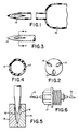
- FIG. 1 relates to an enlarged longitudinal sectional view, partially broken, of a syringe, the barrel and tubular needle being integrally formed, the needle possessing the unique ported-conical injection end.
- FIG. 2 is directed to an end view of the injection device.
- the number of ports may be more or less than the three depicted. As depicted, the portals are flush with the exterior of the device.
- FIG. 3 relates to a side view of the injection device with line 4-4.
- FIG. 4 is the cross section through FIG. 3 at line 4-4 which relates to the shape of the portals wherein the side walls of the portal are configured so as to impart an angular momentum or torque to the injected fluid.
- Reference numeral 13 is a portal which possesses side walls that have leading and following faces that are angled or slanted so that a torque is applied to the injectate that results in the swirling motion of the fluid.
- FIG. 5 relates to a sectional view of a two-part mold that upon closure will form the novel injection end of this invention.
- the reference numerals 16 represent the cutting blades which will produce side walls that will impart an angular momentum to the fluid.
- FIG. 6 relates to a blood gathering needle having the customary collar, customary needle end and the novel end of this invention.
- This device is unitary in construction.
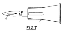
- FIG. 7 relates to a unitary construction possessing the novel end and a Luer adaptor.
- the hollow fluid-transmitting needle is of a unitary construction and comprises the novel injection end of this invention 10 and a conventional end or Luer hub 11 for insertion onto a capsule or ampule that contains the fluid to be injected.
- the collar 11 is for anchoring the needle to the syringe or injection device.
- the needle and collar combination is of one-piece transparent or translucent material.
- the needle with novel end 10 and ampule 12 are of one material and one part, and the production of the needle and annual is made in accordance with the known practices in the art of molding, such as molding by extrusion or casting.
- the cross section through 4-4 illustrates the ports 13 that are configured so as to impart an angular momentum to the fluid being injected, that is the fluid injected exists at a direction other than parallel with the axis of the needle and in a spiral manner.
- the ports 13 are cut with blades 16 from FIG. 5 or are cut with the use of a laser.
- the most important aspect of these portals whether tear drop in shape, rectangular, and so on is that the walls or faces be configured so as to produce the swirling motion.
- the curvature or angles of these walls are not unlike the blades of a turbine or centrifugal pump.
- the injection device of this invention possesses a ported conical end 14 like the taper point of a common needle, it enters the patient via blunt dilatation with no cutting action whatsoever.
- the included angle at the apex of the cone
- the needle's included angle is more acute, less work per unit time would be required to make a fully developed hole.
- the more acute the angle the more fragile the tip, with resultant possible failure.
- the angle is much greater than 20°, the dilatation per unit time must be faster and the needle appears to be more blunt because of the necessity for rapid dilatation.
- the portals are flush with the exterior of the device. This means that the instant device does not possess any channels, shoulders or other surfaces that interrupt the converging forward of the outer surface of the device to a needle sharp point. Many of the prior art devices possess channels or shoulders which would increase the discomfort experienced since these additional surfaces or features would cause tearing or compression of the skin.
- the end view depicts three exit portals 13 that will provide for injection of the fluid in a swirling manner.
- the number of portals may range from 2 to 4 with 3 being preferred.
- the two parts of the mold 15 and 14 close on the preformed tube or needle to cut or form the exit portals.
- the cutting blades 16 are sharp and may be heated to above the melting point of the polymer.
- the cutting blades in this embodiment are triangular in cross section with different angles for each of the two surfaces with respect to a line from the apex of the triangle to the base of the triangle, said line is perpendicular to the base of the triangle. These different angles are such that an angular momentum or torque is applied to the injectate.
- novel end 10 is in combination with a conventional collar 17 and the prior art needle end 18.
- This device is unitary in construction and has utility in the gathering of fluids from a patient.
- polymeric materials which can be used to construct the instant invention are the polycarbonates, polyesters, acrylates, polyaramides, polyamides, polyetheretherketones, modified phenylene oxides, polyetherimides, polymethylpentenes, polysulfones, and other know polymeric materials that are transparent, have compatibility with living tissue and the structural integrity required to penetrate living tissue.
- the medical appliance of the subject invention is made of polymeric materials which meet the non-toxicity requirements specified by the appropriate governmental authorities. Polymeric materials are known to meet such requirements and possess the required stiffness for penetration, transparency, and yet process with ease.
- One preferred procedure involves the extruding or drawing of a tube to the desired size.
- a LuciteTM tube with an outside diameter of 0.635cm (1/4") with an inside diameter of 0.318cm (1/8") and a wall thickness of 0.159cm (1/16") was heated to about the glass transition temperature of LuciteTM.
- the tube in a vertical direction was pulled or drawn to a gauge of approximately 18 through the use of a pulling or drawing action. This drawing or pulling of the tube narrows its dimensions and is done in such a manner so as to result in a tube of the required size for use as a hypodermic device.
- the temperature at which the drawing can be conducted is at or about the glass transition temperature of the polymer.
- each polymer such as polyester, polycarbonate, acrylic, etc.
- drawing fibers such as polyester fibers, will appreciate the drawing rates and initial tubular dimensions required to result in a tube of the appropriate size for use as a hypodermic device.
- This fine tube is then placed in a two-section mold that upon closing places the injection end and ports on the tube.
- the mold is segmented and contains protrusions that on closing of the mold forms the ports as depicted in FIG. 5.
- protrusions are triangular in cross section with angles relative to the base of the triangle that are different for each surface.
- angles will be required to achieve the side wall configuration of the portal so as to provide a torque or angular momentum to the injectate.
- the exit portal side walls create a torque upon the exiting fluid. This torque gives rise to the production of a flow which has a two vector direction.
- the leading and following faces of the portal side walls are at different angles so as to impart the torque.
- the rate of dissipation of energy in a fluid depends only on the viscosity of the fluid and on the instantaneous distribution of that velocity. Since velocity is a function of pressure, the rate of dissipation of energy can be altered by the design of the exit port. Thus, the dispersal created by the two exit vectors will dissipate the energy in an uniform manner and, therefore, the pressure needed to mobilize the fluid will be minimal as compared to an open end system such as the conventional bias cut tube.
- the key of the instant invention resides in the torque or angular momentum imparted on the exiting fluid which readily dissipates the energy.
- the instant invention will provide an injection made with less force and thus less tissue damage.
- the shape of the exit portal side walls will create the circular flow with a small loss of energy in the form of turbulence which is less than the energy lost to turbulence in an open end system.
- Another preferred procedure to form the novel injection end of the instant invention is to injection mold the needle shape, and then using a laser, burn or cut the polymer to form the ports.
- the laser would cut one wall of the port at an appropriate angle and then the opposite wall or face at a different angle so that the fluid would have a torque applied to it.
- Those angles can be varied and are readily ascertainable by one knowledgeable in turbine and centrifugal pump design.
- novel injection device can be produced via technologies such as injection molding, cutting with drills and/or knives, cutting with lasers, extrusion and the like.
- the exterior dimensions of the device of this invention are those that are customary in the art. Preferably, 18 gauge to 25 gauge needles are contemplated.
- the area of the portals is preferably the maximum that can be obtained with the process of manufacture and the polymer utilized.
- the device of the instant invention can also be produced through extrusion. As in conventional polymer technology, the material is heated and then forced through a die at an appropriate speed and pressure. This extruded tube may then be drawn or pulled to achieve the appropriate size for a hypodermic device.
- the polymer is initially heated in an extruder or a similar installation equipped with a heating and mixing device, to or above its melting or softening point, the extruded tube is partially cooled below the melting point, optionally drawing to a fine structure, and subsequently in an accessory installation submitted to further processing to place the novel end on the device via a forming device, compression molding or another accessory installation.
- a structure forming process is described in DE-OS NO. 2856580, which is herein incorporated by reference.
- extrusion conditions depend upon the individual polymer used, the amount of optionally present processing aids, the amount of additives optionally employed and of fillers, for example calcium carbonate, glass fibers, short fibers and the like.
- the tube is cut at an angle perpendicular to the axis of the tube. This cut end is then inserted into a heated mold of FIG. 5 that will provide the injection end which is described herein. Two molds may be used in that the first would place the point on the needle, and the second would cut or shape the portals for the needle.
- One preferred method of producing the device of this invention is injection molding.
- the molds themselves should be carefully grated and have an overflow area because it is extremely difficult to fill the mold with "just enough" material.
- Presently available equipment using highly sophisticated process control devices on small single or multi-cavity molds will result in the best possible hypodermic device.
- the mold steel or other metal should be neutralized by commercial chemicals and then coated to prevent degradation of the metal.
- Stainless steel like 440SS, 420SS or others are suggested.
- the mold should be cleaned before the next molding so as to prevent contamination of the next device to be molded.
- a molding machine of one or two ounce capacity with a general purpose screw design is useful in making the device. It is suggested that the recommendations of the polymer supplier be followed as to set-up of the molding machine.
- the manner of injection molding the respective portions of the device within the purview of this invention is subject to a diversification of procedures within the preference and skill of one versed in the molding art.
- the device may be molded from crosslinked polymer or from an intermediate stage polymer and the article subsequently polymerized to the final stage.
- the fabricated devices may be sterilized with ethylene-oxide, steam sterilization, gamma irradiation, or other known techniques.
- the shape of the sidewalls of the ports or portals are such that the fluid to be injected exits with an angular momentum or swirling motion.
- These ports may be square, rectangular, circular, oval, teardrop or fluted in shape but all have the characteristic feature of the slanted or angled side walls as depicted in FIG. 4.
- the preferred shape is fluted in that not only does the fluid to be injected exit the ports in a direction other than parallel to the axis of the needle, but also in a spiral or circular manner, thus lessening the chances of tissue damage.
- This fluted port is formed so that the exiting fluid has an angular momentum imparted to it.
- This fluted port can be formed through the use of a mold that cuts or forms the fluted port, through injection molding of the device or through cutting the ports with a laser.
- Polymers and additives which meet the criteria of bio-compatibility are too numerous to mention, as the state of polymer technology has advanced to a high degree.
- Useful polymers are those mentioned above. These polymers are compounded to yield translucent or transparent materials in order to permit observation of the prevailing conditions in the needle.
- the polymeric needle of the present invention lends itself to a fine conical point.
- a further advantage of the present invention over the prior art is that presently accepted steel needles due to their configuration "core" or remove tissue as part of penetration.
- the device of this invention through its unique injection end lessens or eliminates the coring of tissue.
- the instant device is more like a solid steel pin, in that no tissue is cored; only a puncture would results from its use.
- polymers have less drag in tissue than steel, thus, further lessening trauma to the surrounding tissue.
- One embodiment of the invention is the novel injection end being part of a unitary needle and barrel.
- a simple, sturdy, minimum weight, economical and practical hypodermic injection syringe in the form of an integral or single unitary member, which can be preloaded with the medication to be injected, i.e., insulin.
- This and the other embodiments of the invention allow for sterile packaging that is known in the art and then the efficient destruction of the device after its use. The destruction is most effective either through mechanical damage or exposure to temperatures above the glass transition temperature of the polymer.
- a device as described herein that is filled at an appropriate laboratory under controlled conditions of sterility, shipped and then distributed. Sterile conditions are maintained through the use of sheaths or covers as known in the medical profession. Following use, the device may be destroyed or discarded.
- the invention is predicated on a novel type of hypodermic injection device or syringe that possesses a structurally novel type of injected end.
- the use of a polymeric material in combination with a "non-coring" or ported configuration for a hypodermic device overcomes numerous disadvantages presently tolerated by the medical profession and patients alike.
Landscapes
- Health & Medical Sciences (AREA)
- Vascular Medicine (AREA)
- Engineering & Computer Science (AREA)
- Anesthesiology (AREA)
- Biomedical Technology (AREA)
- Heart & Thoracic Surgery (AREA)
- Hematology (AREA)
- Life Sciences & Earth Sciences (AREA)
- Animal Behavior & Ethology (AREA)
- General Health & Medical Sciences (AREA)
- Public Health (AREA)
- Veterinary Medicine (AREA)
- Infusion, Injection, And Reservoir Apparatuses (AREA)
Claims (5)
- Injektionsvorrichtung mit
einem Injektionsende (10), welches einen mit Öffnungen versehenen Aufbau aufweist, der den zu injizierenden Stoff in einer anderen Richtung als parallel zur Achse der Vorrichtung abgibt, und der von konischer Gestalt ist und oberhalb eines festen konischen Einstichpunktes (14) Öffnungen (13) aufweist;
äußeren Oberflächen der Vorrichtung, die ohne Unterbrechung von gegenüberliegenden Seiten eines Rohres zu einem nadelscharfen Punkt (14) zusammenlaufen;
wobei zwei oder mehrere Öffnungen (13) mit dem Äußeren der Außenoberfläche der Vorrichtung fluchten;
dadurch gekennzeichnet, daß(a) die Injektionsvorrichtung aus einem polymeren Material gebaut ist;(b) die zwei oder mehreren Öffnungen (13) entlang dem Außendurchmesser der Vorrichtung in gleichen Abständen angeordnet sind; und(c) die Öffnungen (13) turbinenähnliche Seitenwände mit gewinkelten oder geneigten Leit- und Austrittsflächen haben, um dem zu injizierenden Fluid einen Drehimpuls oder ein Drehmoment zu verleihen. - Injektionsvorrichtung nach Anspruch 1, dadurch gekennzeichnet, daß das polymere Material ausgewählt ist aus der Gruppe Polycarbonate, Polyester, Acrylate, Polyaramide, Polyamide, Polyetheretherketone, modifizierte Phenylenoxide, Polyetherimide, Polymethylpentene und Polysulfone.
- Injektionsvorrichtung nach einem der vorhergehenden Ansprüche, dadurch gekennzeichnet, daß der konische Einstichpunkt (14) einen Winkel von 10 bis 22 ° aufweist.
- Injektionsvorrichtung nach einem der vorhergehenden Ansprüche, dadurch gekennzeichnet, daß der konische Einstichpunkt (14) einen Winkel von 12 bis 18 ° aufweist.
- Injektionsvorrichtung nach einem der vorhergehenden Ansprüche, dadurch gekennzeichnet, daß die Öffnungen (13) kreisförmige Gestalt haben.
Applications Claiming Priority (2)
| Application Number | Priority Date | Filing Date | Title |
|---|---|---|---|
| US944322 | 1986-12-19 | ||
| US06/944,322 US4838877A (en) | 1985-08-06 | 1986-12-19 | Polymeric hypodermic device |
Publications (3)
| Publication Number | Publication Date |
|---|---|
| EP0271775A2 EP0271775A2 (de) | 1988-06-22 |
| EP0271775A3 EP0271775A3 (en) | 1988-11-23 |
| EP0271775B1 true EP0271775B1 (de) | 1991-07-31 |
Family
ID=25481194
Family Applications (1)
| Application Number | Title | Priority Date | Filing Date |
|---|---|---|---|
| EP87117844A Expired EP0271775B1 (de) | 1986-12-19 | 1987-12-02 | Hypodermische Vorrichtung aus einem Polymer |
Country Status (5)
| Country | Link |
|---|---|
| US (1) | US4838877A (de) |
| EP (1) | EP0271775B1 (de) |
| JP (1) | JPS63260571A (de) |
| CA (1) | CA1276850C (de) |
| DE (1) | DE3771856D1 (de) |
Families Citing this family (144)
| Publication number | Priority date | Publication date | Assignee | Title |
|---|---|---|---|---|
| US5324256A (en) * | 1987-07-31 | 1994-06-28 | Lawrence A. Lynn | Apparatus and methods for transferring blood between aspiration assembly and an external container |
| US5178607A (en) * | 1987-07-31 | 1993-01-12 | Lynn Lawrence A | Blood aspiration assembly septum and blunt needle aspirator |
| EP0354947B1 (de) * | 1988-01-25 | 1994-07-20 | BAXTER INTERNATIONAL INC. (a Delaware corporation) | Vorgeschlitzte injektionsvorrichtung sowie konische kanüle |
| NL8803204A (nl) * | 1988-12-29 | 1990-07-16 | Tno | Voor eenmalig gebruik bestemde medicinale naald. |
| DE3927290A1 (de) * | 1989-08-18 | 1991-02-21 | Eska Medical & Kunststofftechn | Punktionskanuele |
| US5151231A (en) * | 1990-03-19 | 1992-09-29 | Becton, Dickinson And Company | Method for making liquid crystalline tube having a point |
| US5250066A (en) * | 1990-03-19 | 1993-10-05 | Becton Dickinson And Company | Plastic pointed articles and method for their preparation |
| US5515871A (en) * | 1990-09-28 | 1996-05-14 | Sulzer Brothers Ltd. | Hollow needle for medical use and a laser method for manufacturing |
| DE4109864C2 (de) * | 1991-03-26 | 1993-11-04 | Johann Dr Med Rull | Stanzfreie injektionskanuele |
| US5176643A (en) * | 1991-04-29 | 1993-01-05 | George C. Kramer | System and method for rapid vascular drug delivery |
| US5451210A (en) * | 1991-04-29 | 1995-09-19 | Lifequest Medical, Inc. | System and method for rapid vascular drug delivery |
| US5607401A (en) * | 1991-09-03 | 1997-03-04 | Humphrey; Bruce H. | Augmented polymeric hypodermic devices |
| US5458614A (en) * | 1991-09-03 | 1995-10-17 | Humphrey; Bruce H. | Augmented polymeric hypodermic devices |
| US5254106A (en) * | 1992-04-17 | 1993-10-19 | Feaster Fred T | Hydrodissection needle |
| US5294325A (en) * | 1992-07-09 | 1994-03-15 | World Precision Instruments, Inc. | Miniaturized fluid conveying device and methods of use thereof |
| US5226900A (en) * | 1992-08-03 | 1993-07-13 | Baxter International Inc. | Cannula for use in drug delivery systems and systems including same |
| US5312376A (en) * | 1992-10-29 | 1994-05-17 | Critikon, Inc. | Catheter with clear needle shaft |
| US5738650A (en) * | 1993-01-29 | 1998-04-14 | Becton, Dickinson And Company | Subarachnoid needle and method for administering therapeutic agents to the subarachnoid space |
| AU676281B2 (en) * | 1993-03-09 | 1997-03-06 | Ssb Technology Pty Ltd | Method of manufacturing needles |
| CA2157568C (en) * | 1993-03-09 | 2001-10-02 | John Frederick Stevens | Method of manufacturing needles |
| US5322516A (en) * | 1993-05-20 | 1994-06-21 | Cobe Laboratories, Inc. | Safety needle system and method for using the same |
| US5449351A (en) * | 1993-09-09 | 1995-09-12 | Zohmann; Walter A. | Atraumatic needle for lumbar puncture |
| US5360416A (en) * | 1993-09-30 | 1994-11-01 | Sherwood Medical Company | Thin-walled anesthesia needles |
| US5522804A (en) * | 1994-02-15 | 1996-06-04 | Lynn; Lawrence A. | Aspiration, mixing, and injection syringe |
| US5632728A (en) * | 1994-02-22 | 1997-05-27 | Lincoln Diagnostics, Inc. | Skin testing and vaccinating needles |
| GB2287319B (en) * | 1994-03-12 | 1998-02-25 | John Francis Cockburn | Medical apparatus for ultrasonic methods of ultrasonic imaging |
| DE69506017T2 (de) * | 1994-03-17 | 1999-10-07 | Terumo K.K., Tokio/Tokyo | Kunstharznadel |
| EP0727187B1 (de) * | 1995-02-15 | 2003-08-06 | Joseph Eldor | Spinalnadel mit mehreren Löchern |
| GB2298368B (en) * | 1995-02-22 | 1999-01-20 | John Francis Cockburn | Medical needle assembly for use in ultrasound imaging |
| US5807304A (en) * | 1995-03-09 | 1998-09-15 | Cockburn; John F. | Medical needle for use in ultrasound imaging |
| US5577368A (en) * | 1995-04-03 | 1996-11-26 | Johnson & Johnson Professional, Inc. | Method for improving wear resistance of polymeric bioimplantable components |
| DE19512607A1 (de) * | 1995-04-04 | 1996-10-10 | Johann Dr Med Rull | Völlig tragmentationsfreie Kanülen |
| US5683378A (en) * | 1995-06-27 | 1997-11-04 | Christy; William J. | Endoscopic wound access and anchoring device method |
| GB2304580A (en) * | 1995-08-31 | 1997-03-26 | Jocelyn Asher Simon Brookes | Magnetic resonance-compatible needle |
| WO1997015341A1 (en) * | 1995-10-23 | 1997-05-01 | Racz Gabor J Jr | Stellate block needle |
| US5662619A (en) * | 1995-11-27 | 1997-09-02 | Zarate; Alfredo R. | Venous dialysis needle |
| US5634913A (en) * | 1996-01-23 | 1997-06-03 | Stinger; Florence | Softening conduit for carrying fluids into and out of the human body |
| IE80772B1 (en) * | 1996-06-10 | 1999-02-10 | Elan Corp Plc | Delivery needle |
| NZ333321A (en) | 1996-06-10 | 2000-08-25 | Elan Corp Plc | Needle for subcutaneous delivery of fluids, slots in needle near tip |
| US6096012A (en) * | 1996-08-27 | 2000-08-01 | Johnson & Johnson Medical, Inc. | Coated one-piece composite plastic catheter and cannula |
| CA2274603C (en) | 1996-12-16 | 2007-05-01 | Board Of Supervisors Of Louisiana State University And Agricultural And Mechanical College | Blunt tip cannula with access pin |
| US5762630A (en) * | 1996-12-23 | 1998-06-09 | Johnson & Johnson Medical, Inc. | Thermally softening stylet |
| DE19717253A1 (de) * | 1997-04-24 | 1998-10-29 | Edwin Dr Med Klaus | Universal-Ideal-Nadel |
| US6695821B1 (en) | 1998-06-17 | 2004-02-24 | Raymond N. Sjaarda | Surgical infusion tool with flow diffuser |
| US6358236B1 (en) * | 1998-08-06 | 2002-03-19 | Baxter International Inc. | Device for reconstituting medicaments for injection |
| GB9817662D0 (en) | 1998-08-13 | 1998-10-07 | Crocker Peter J | Substance delivery |
| US6165158A (en) * | 1998-10-14 | 2000-12-26 | Advanced Cardiovascular Systems, Inc. | Lubricious catheter shaft |
| DE19911970A1 (de) * | 1999-03-17 | 2000-09-28 | Medinorm Ag | Kanüle für Ports |
| DE19933171A1 (de) * | 1999-06-18 | 2000-12-21 | Medos Medizintechnik Gmbh | Verfahren zum Einbringen eines Fluides in ein Gefäß des menschlichen Körpers sowie entsprechende Kanüle |
| US6800073B2 (en) | 1999-10-28 | 2004-10-05 | Scimed Life Systems, Inc. | Biocompatible pharmaceutical articles |
| US6663606B1 (en) | 1999-10-28 | 2003-12-16 | Scimed Life Systems, Inc. | Biocompatible medical devices |
| US8808272B2 (en) * | 1999-10-28 | 2014-08-19 | Boston Scientific Scimed, Inc. | Biocompatible medical devices |
| US6241710B1 (en) * | 1999-12-20 | 2001-06-05 | Tricardia Llc | Hypodermic needle with weeping tip and method of use |
| US7243689B2 (en) | 2000-02-11 | 2007-07-17 | Medical Instill Technologies, Inc. | Device with needle penetrable and laser resealable portion and related method |
| RU2188040C2 (ru) * | 2000-07-07 | 2002-08-27 | Общество с ограниченной ответственностью Научно-технический центр "Мепотекс" | Устройство для введения жидкости в организм человека |
| US6695860B1 (en) | 2000-11-13 | 2004-02-24 | Isense Corp. | Transcutaneous sensor insertion device |
| US6936031B2 (en) * | 2000-12-12 | 2005-08-30 | Gambro Dasco S.P.A. | Site for access to the inside of a channel, and corresponding cannula |
| USD457626S1 (en) | 2000-12-29 | 2002-05-21 | Barry Farris | Integrated spike and syringe |
| USD457953S1 (en) | 2000-12-29 | 2002-05-28 | Barry Farris | Integrated spike and syringe |
| USD472317S1 (en) | 2000-12-29 | 2003-03-25 | Barry Farris | Integrated spike and syringe |
| USD458677S1 (en) | 2000-12-29 | 2002-06-11 | Barry Farris | Integrated spike and syringe |
| USD487149S1 (en) | 2000-12-29 | 2004-02-24 | Zephyr Cove | Integrated spike and syringe |
| US6969373B2 (en) * | 2001-04-13 | 2005-11-29 | Tricardia, Llc | Syringe system |
| US6887857B2 (en) * | 2001-04-27 | 2005-05-03 | Scimed Life Systems, Inc. | Microparticle protection of therapeutic agents |
| US6749792B2 (en) * | 2001-07-09 | 2004-06-15 | Lifescan, Inc. | Micro-needles and methods of manufacture and use thereof |
| US7186241B2 (en) * | 2001-10-03 | 2007-03-06 | Medical Instill Technologies, Inc. | Syringe with needle penetrable and laser resealable stopper |
| US6726649B2 (en) * | 2001-12-28 | 2004-04-27 | Becton, Dickinson And Company | Medical needle assemblies |
| US20040039340A1 (en) * | 2001-12-28 | 2004-02-26 | Becton, Dickinson And Company | Shieldable unit dose medical needle assemblies |
| US6730059B2 (en) | 2001-12-28 | 2004-05-04 | Becton, Dickinson And Company | Medical needle assemblies |
| US20040054334A1 (en) * | 2001-12-28 | 2004-03-18 | Prais Alfred W. | Medical needle assemblies |
| US20030121812A1 (en) * | 2001-12-28 | 2003-07-03 | Sprieck Terry L. | Medical needle assemblies |
| US20030125677A1 (en) * | 2001-12-28 | 2003-07-03 | Becton, Dickinson And Company | Medical needle assemblies |
| AU2003209607A1 (en) * | 2002-04-17 | 2003-10-27 | Tracetrack Technology Ltd. | Contaminant scanning system |
| JP4179991B2 (ja) * | 2002-04-26 | 2008-11-12 | ミリポア・コーポレイション | 使い捨て無菌流体輸送デバイス |
| USD476418S1 (en) | 2002-05-09 | 2003-06-24 | Becton, Dickinson And Company | Medical needle assembly |
| USD471980S1 (en) | 2002-05-09 | 2003-03-18 | Becton, Dickinson And Company | Medical needle assembly |
| USD476417S1 (en) | 2002-05-09 | 2003-06-24 | Becton, Dickinson And Company | Medical needle assembly |
| USD476733S1 (en) | 2002-05-09 | 2003-07-01 | Becton, Dickinson And Company | Medical needle assembly |
| USD476419S1 (en) | 2002-05-09 | 2003-06-24 | Becton, Dickinson And Company | Medical needle assembly |
| US10973545B2 (en) | 2002-05-31 | 2021-04-13 | Teleflex Life Sciences Limited | Powered drivers, intraosseous devices and methods to access bone marrow |
| US7811260B2 (en) * | 2002-05-31 | 2010-10-12 | Vidacare Corporation | Apparatus and method to inject fluids into bone marrow and other target sites |
| IL165224A0 (en) | 2002-05-31 | 2005-12-18 | Vidacare Corp | Apparatus and method to access bone marrow |
| US8668698B2 (en) | 2002-05-31 | 2014-03-11 | Vidacare Corporation | Assembly for coupling powered driver with intraosseous device |
| US8641715B2 (en) | 2002-05-31 | 2014-02-04 | Vidacare Corporation | Manual intraosseous device |
| US11337728B2 (en) | 2002-05-31 | 2022-05-24 | Teleflex Life Sciences Limited | Powered drivers, intraosseous devices and methods to access bone marrow |
| ES2454190T3 (es) * | 2002-07-26 | 2014-04-09 | Emd Millipore Corporation | Conector estéril |
| WO2004024219A1 (en) * | 2002-09-10 | 2004-03-25 | Becton Dickinson And Company | Method and apparatus for epidermal delivery of a substance |
| DE10248377A1 (de) | 2002-10-17 | 2004-05-06 | Haindl, Hans, Dr.med. | Kanüle, insbesondere für die Spinalanästhesie sowie Verfahren zu deren Herstellung |
| US7487689B2 (en) * | 2003-01-15 | 2009-02-10 | Tracetrack Technology Ltd. | Contaminant scanning system |
| US9504477B2 (en) | 2003-05-30 | 2016-11-29 | Vidacare LLC | Powered driver |
| US7588557B2 (en) * | 2003-09-24 | 2009-09-15 | Granit-Medical Innovations, Llc | Medical instrument for fluid injection and related method |
| US7293477B2 (en) * | 2003-12-23 | 2007-11-13 | Millipore Corporation | Disposable, pre-sterilized fluid receptacle sampling device |
| RU2255655C1 (ru) * | 2004-02-13 | 2005-07-10 | Попов Михаил Юрьевич | Устройство для взятия крови |
| JP4500851B2 (ja) * | 2004-03-12 | 2010-07-14 | エイジェンシー・フォー・サイエンス,テクノロジー・アンド・リサーチ | 横穴付きマイクロ針の製造に使用するための方法および型 |
| GB2419586B (en) | 2004-04-02 | 2008-07-09 | Howard Silvers & Sons Pty Ltd | Drink pouring dispenser |
| US20060079848A1 (en) * | 2004-06-29 | 2006-04-13 | Becton, Dickinson And Company | Non-skin penetrating reconstituting syringe |
| US20060079839A1 (en) * | 2004-06-29 | 2006-04-13 | Becton, Dickinson And Company | Single-use syringe |
| SE0402100D0 (sv) * | 2004-08-30 | 2004-08-30 | Bonsens Ab | Molded micro-needles |
| USD536925S1 (en) * | 2005-01-11 | 2007-02-20 | Macler Jeffrey E | Spike |
| US7651482B2 (en) * | 2005-02-04 | 2010-01-26 | Boston Scientific Scimed, Inc. | Non-coring needles and methods of manufacturing same |
| US8540686B2 (en) * | 2005-03-02 | 2013-09-24 | Covidien Ag | Blunt tip vial access cannula |
| RU2284752C1 (ru) * | 2005-03-02 | 2006-10-10 | Михаил Юрьевич Попов | Устройство для взятия крови |
| RU2284751C1 (ru) * | 2005-03-02 | 2006-10-10 | Михаил Юрьевич Попов | Устройство для взятия крови |
| US7666172B2 (en) * | 2005-03-15 | 2010-02-23 | Plaridel Cerna Atil | Medical needle having a closed tip |
| GB2424417B (en) * | 2005-03-24 | 2008-11-12 | Amersham Health As | Devices and method for the penetration of a container stopper |
| JP2006271651A (ja) * | 2005-03-29 | 2006-10-12 | Matsumoto Shika Univ | 液体注入用針部品、及びその製造方法 |
| US20090209923A1 (en) * | 2005-04-19 | 2009-08-20 | Linderoth Soeren | Disposable hypodermic needle |
| US20070078429A1 (en) * | 2005-06-15 | 2007-04-05 | Inviro Medical Devices Ltd. | Safety fluid transfer cannula |
| RU2320311C1 (ru) * | 2006-07-18 | 2008-03-27 | Марият Мурадалиевна Мухина | Способ пролонгированного воздействия на акупунктурные точки и игла (варианты) для него |
| AU2006270526B2 (en) | 2005-07-20 | 2013-01-24 | Frey Medical Technologies Ag | Method for stimulating the organism biochemical reactions for treating organs and tissues, a board for carrying out said method and a board emitter |
| US20070132597A1 (en) * | 2005-12-09 | 2007-06-14 | Valence Broadband, Inc. | Methods and systems for monitoring patient support exiting and initiating response |
| US20070191875A1 (en) * | 2006-02-16 | 2007-08-16 | Om Prakash Rehil | Apparatus to facilitate penetration into a body cavity or lumen formed by body tissue, and method for using same |
| JP2009534148A (ja) * | 2006-04-26 | 2009-09-24 | ノボ・ノルデイスク・エー/エス | テーパ状端部を有する注入デバイス用カニューレ、及び同カニューレの製造方法 |
| US8944069B2 (en) | 2006-09-12 | 2015-02-03 | Vidacare Corporation | Assemblies for coupling intraosseous (IO) devices to powered drivers |
| FR2912919B1 (fr) * | 2007-02-22 | 2009-05-01 | Bernard Perriere | Dispositif d'injection miniaturise a usage medical |
| SG153002A1 (en) | 2007-11-16 | 2009-06-29 | Millipore Corp | Fluid transfer device |
| US8721603B2 (en) | 2008-01-15 | 2014-05-13 | West Pharmaceutical Services, Inc. | Syringe with co-molded hub and cannula |
| CN101896214B (zh) * | 2008-01-15 | 2013-05-29 | 西部制药服务公司 | 将插管模制到注射器针筒上的筒夹机构和方法 |
| US7938800B2 (en) * | 2008-05-13 | 2011-05-10 | Lawrence R. Koh and Nina Merrell-Koh | Needleshield assembly and methods of use |
| US8382722B2 (en) | 2008-06-30 | 2013-02-26 | Covidien Lp | Blunt tip vial access cannula and method for manufacture |
| WO2010006186A1 (en) * | 2008-07-09 | 2010-01-14 | Grantadler Corporation | Needle for subcutaneous port |
| WO2010026644A1 (ja) * | 2008-09-05 | 2010-03-11 | Okumura Tsuneo | 医療用無痛注射針 |
| FR2940440B1 (fr) * | 2008-12-18 | 2010-12-24 | Millipore Corp | Dispositif pour le transfert d'un milieu |
| FR2940439B1 (fr) * | 2008-12-18 | 2011-02-11 | Millipore Corp | Dispositif pour le transfert d'un milieu |
| EP2238998A1 (de) | 2009-04-02 | 2010-10-13 | F. Hoffmann-La Roche AG | Kanüle zum Durchstechen eines Septums einer Kartusche und Ventil für die Kanüle |
| BRPI0910083A2 (pt) * | 2009-04-22 | 2012-02-28 | Universidade Federal De Pernambuco | agulha com duplo bisel para lise de microvarizes e telangiectasias |
| US8544497B2 (en) | 2009-10-30 | 2013-10-01 | Emd Millipore Corporation | Fluid transfer device and system |
| US20110137266A1 (en) * | 2009-12-07 | 2011-06-09 | Michael Schlitt | Catheter |
| US20120116324A1 (en) * | 2009-12-07 | 2012-05-10 | Michael Schlitt | Catheter |
| EP2547393B1 (de) | 2010-03-15 | 2020-12-30 | EntraTympanic, LLC | Vorrichtung zur verabreichung eines medikaments in die paukenhöhle mit gleitunterstützung |
| US9125992B2 (en) | 2011-09-16 | 2015-09-08 | Melvin A. Finke | Fluid delivery device with filtration |
| USD693002S1 (en) | 2011-09-21 | 2013-11-05 | West Pharmaceutical Services, Inc. | Hub for medical container |
| JP5500742B2 (ja) * | 2012-03-19 | 2014-05-21 | 株式会社ユニシス | 脊椎くも膜下麻酔針の製造方法 |
| USD689188S1 (en) | 2012-07-19 | 2013-09-03 | West Pharmaceutical Services, Inc. | Syringe plunger rod |
| US20140100426A1 (en) * | 2012-08-03 | 2014-04-10 | Ipsyrng Capital Development, Llc | Blunt tip cannula for injection of a material into a patient |
| US9155862B2 (en) * | 2012-09-28 | 2015-10-13 | Covidien Lp | Symmetrical tip acute catheter |
| US9308020B2 (en) | 2013-03-14 | 2016-04-12 | Cook Medical Technologies Llc | Tri-fluted vascular access needle |
| JP6411944B2 (ja) * | 2015-05-11 | 2018-10-24 | 典雄 宮城 | 注射針と注射針の製造方法 |
| CN109069740B (zh) | 2016-04-22 | 2021-10-29 | 伊莱利利公司 | 用于减少胰岛素中的间甲酚浓度的具有包含聚合吸着剂的组件的输注组 |
| JP6524392B2 (ja) * | 2016-11-15 | 2019-06-05 | 群馬県 | 注射針つきシリンジ |
| US11160934B2 (en) * | 2017-05-10 | 2021-11-02 | Galderma Holding SA | Conical needle and methods of use and manufacturing |
| WO2022181527A1 (ja) * | 2021-02-25 | 2022-09-01 | 株式会社狭山金型製作所 | 針管、針管ユニット、注射針 |
| JP2023010404A (ja) * | 2021-07-09 | 2023-01-20 | 株式会社狭山金型製作所 | 注射針 |
| JP2023010403A (ja) * | 2021-07-09 | 2023-01-20 | 株式会社狭山金型製作所 | 注射針 |
Family Cites Families (10)
| Publication number | Priority date | Publication date | Assignee | Title |
|---|---|---|---|---|
| US2097039A (en) * | 1935-09-21 | 1937-10-26 | Peterson Alfred Martin | Trocar |
| US2954768A (en) * | 1954-06-14 | 1960-10-04 | Baxter Don Inc | Puncture point |
| FR1142769A (fr) * | 1956-02-20 | 1957-09-23 | Aiguille pour injections intramusculaires | |
| US3127894A (en) * | 1960-09-26 | 1964-04-07 | Gail B Smith | Method of medicine administration and device therefor |
| US3831814A (en) * | 1969-07-25 | 1974-08-27 | Cutter Lab | Trocar-cannula |
| JPS59141957A (ja) * | 1983-02-04 | 1984-08-14 | テルモ株式会社 | 留置カテ−テルおよびその製造方法 |
| JPS6162468A (ja) * | 1984-09-05 | 1986-03-31 | テルモ株式会社 | 医療用穿刺針 |
| US4699612A (en) * | 1985-04-01 | 1987-10-13 | Hamacher Edward N | Infusion needle |
| DE3600496A1 (de) * | 1986-01-10 | 1987-07-16 | Josef Magasi | Punktionskanuele, deren griff sowie verfahren zu deren herstellung |
| US4710180A (en) * | 1986-10-06 | 1987-12-01 | Johnson Gerald W | Lipoject needle |
-
1986
- 1986-12-19 US US06/944,322 patent/US4838877A/en not_active Expired - Fee Related
-
1987
- 1987-11-26 CA CA000552818A patent/CA1276850C/en not_active Expired - Lifetime
- 1987-12-02 DE DE8787117844T patent/DE3771856D1/de not_active Expired - Lifetime
- 1987-12-02 EP EP87117844A patent/EP0271775B1/de not_active Expired
- 1987-12-18 JP JP62321143A patent/JPS63260571A/ja active Pending
Also Published As
| Publication number | Publication date |
|---|---|
| CA1276850C (en) | 1990-11-27 |
| EP0271775A2 (de) | 1988-06-22 |
| US4838877A (en) | 1989-06-13 |
| JPS63260571A (ja) | 1988-10-27 |
| DE3771856D1 (de) | 1991-09-05 |
| EP0271775A3 (en) | 1988-11-23 |
Similar Documents
| Publication | Publication Date | Title |
|---|---|---|
| EP0271775B1 (de) | Hypodermische Vorrichtung aus einem Polymer | |
| KR102708956B1 (ko) | 바늘 및 카테터 삽입 디바이스 | |
| KR100499737B1 (ko) | 피복된플라스틱카테터및캐뉼러의일체식합성체 | |
| US3584624A (en) | Flexible intravenous catheter provided with cutting tip means | |
| US5250035A (en) | Cannula and stylet system | |
| US5478328A (en) | Methods of minimizing disease transmission by used hypodermic needles, and hypodermic needles adapted for carrying out the method | |
| US3633579A (en) | Catheter placement device and method | |
| US20030153879A1 (en) | Intravenous infusion needle with soft body | |
| CZ20041044A3 (cs) | Jehla | |
| HK1007484B (en) | Thromboembolectomy device | |
| WO2007070584A2 (en) | Needle constructed with a transparent or translucent material | |
| JP2023129552A (ja) | 針及びカテーテルアセンブリ | |
| KR19980018966A (ko) | 안전 카테터를 위한 적소에 취입된 혈액 밀봉 가스켓(Blown-in-place blood gasket for a safety catheter) | |
| JPS6251632B2 (de) | ||
| US20050010178A1 (en) | Expandable penetrating needle and method of use | |
| JP2022529950A (ja) | 誘導針および関連するカテーテル挿入装置 | |
| US10953159B2 (en) | Endoscopic cannula | |
| US5061244A (en) | Pudendal/paracervical block needle assembly | |
| US20020169426A1 (en) | Injection needle | |
| GB2282760A (en) | Degradable surgical needle | |
| WO2000062843A1 (en) | Tapered intravenous cannula | |
| US12415038B2 (en) | Endoscopic cannula | |
| RU2101035C1 (ru) | Устройство для ретробульбарной анестезии | |
| CN2196486Y (zh) | 锥形多孔注射针头 | |
| JPWO2023167943A5 (ja) | 分割可能な組織切開デバイス及びニードルアセンブリ |
Legal Events
| Date | Code | Title | Description |
|---|---|---|---|
| PUAI | Public reference made under article 153(3) epc to a published international application that has entered the european phase |
Free format text: ORIGINAL CODE: 0009012 |
|
| AK | Designated contracting states |
Kind code of ref document: A2 Designated state(s): DE FR GB IT SE |
|
| PUAL | Search report despatched |
Free format text: ORIGINAL CODE: 0009013 |
|
| AK | Designated contracting states |
Kind code of ref document: A3 Designated state(s): DE FR GB IT SE |
|
| 17P | Request for examination filed |
Effective date: 19881206 |
|
| 17Q | First examination report despatched |
Effective date: 19900529 |
|
| GRAA | (expected) grant |
Free format text: ORIGINAL CODE: 0009210 |
|
| AK | Designated contracting states |
Kind code of ref document: B1 Designated state(s): DE FR GB IT SE |
|
| REF | Corresponds to: |
Ref document number: 3771856 Country of ref document: DE Date of ref document: 19910905 |
|
| ET | Fr: translation filed | ||
| ITF | It: translation for a ep patent filed | ||
| PLBE | No opposition filed within time limit |
Free format text: ORIGINAL CODE: 0009261 |
|
| STAA | Information on the status of an ep patent application or granted ep patent |
Free format text: STATUS: NO OPPOSITION FILED WITHIN TIME LIMIT |
|
| 26N | No opposition filed | ||
| PGFP | Annual fee paid to national office [announced via postgrant information from national office to epo] |
Ref country code: SE Payment date: 19921228 Year of fee payment: 6 |
|
| PGFP | Annual fee paid to national office [announced via postgrant information from national office to epo] |
Ref country code: GB Payment date: 19921229 Year of fee payment: 6 |
|
| PGFP | Annual fee paid to national office [announced via postgrant information from national office to epo] |
Ref country code: FR Payment date: 19921230 Year of fee payment: 6 |
|
| PGFP | Annual fee paid to national office [announced via postgrant information from national office to epo] |
Ref country code: DE Payment date: 19930226 Year of fee payment: 6 |
|
| PG25 | Lapsed in a contracting state [announced via postgrant information from national office to epo] |
Ref country code: GB Effective date: 19931202 |
|
| PG25 | Lapsed in a contracting state [announced via postgrant information from national office to epo] |
Ref country code: SE Effective date: 19931203 |
|
| GBPC | Gb: european patent ceased through non-payment of renewal fee |
Effective date: 19931202 |
|
| PG25 | Lapsed in a contracting state [announced via postgrant information from national office to epo] |
Ref country code: FR Effective date: 19940831 |
|
| REG | Reference to a national code |
Ref country code: FR Ref legal event code: ST |
|
| PG25 | Lapsed in a contracting state [announced via postgrant information from national office to epo] |
Ref country code: DE Effective date: 19941201 |
|
| EUG | Se: european patent has lapsed |
Ref document number: 87117844.8 Effective date: 19940710 |
|
| PG25 | Lapsed in a contracting state [announced via postgrant information from national office to epo] |
Ref country code: IT Free format text: LAPSE BECAUSE OF NON-PAYMENT OF DUE FEES;WARNING: LAPSES OF ITALIAN PATENTS WITH EFFECTIVE DATE BEFORE 2007 MAY HAVE OCCURRED AT ANY TIME BEFORE 2007. THE CORRECT EFFECTIVE DATE MAY BE DIFFERENT FROM THE ONE RECORDED. Effective date: 20051202 |