EP0271334A2 - Verfahren zur Herstellung eines Bildes - Google Patents
Verfahren zur Herstellung eines Bildes Download PDFInfo
- Publication number
- EP0271334A2 EP0271334A2 EP87310838A EP87310838A EP0271334A2 EP 0271334 A2 EP0271334 A2 EP 0271334A2 EP 87310838 A EP87310838 A EP 87310838A EP 87310838 A EP87310838 A EP 87310838A EP 0271334 A2 EP0271334 A2 EP 0271334A2
- Authority
- EP
- European Patent Office
- Prior art keywords
- image
- toner
- light
- retainer
- forming method
- Prior art date
- Legal status (The legal status is an assumption and is not a legal conclusion. Google has not performed a legal analysis and makes no representation as to the accuracy of the status listed.)
- Granted
Links
- 238000000034 method Methods 0.000 title claims abstract description 76
- 238000012546 transfer Methods 0.000 claims abstract description 42
- 230000003595 spectral effect Effects 0.000 claims abstract description 22
- 239000000463 material Substances 0.000 claims abstract description 17
- 238000011161 development Methods 0.000 claims description 24
- 238000004140 cleaning Methods 0.000 claims description 21
- 230000018109 developmental process Effects 0.000 claims 5
- 239000003086 colorant Substances 0.000 description 38
- 230000031700 light absorption Effects 0.000 description 10
- 239000000203 mixture Substances 0.000 description 10
- 238000013019 agitation Methods 0.000 description 8
- 230000003287 optical effect Effects 0.000 description 8
- 230000000694 effects Effects 0.000 description 7
- 239000000049 pigment Substances 0.000 description 7
- 239000006229 carbon black Substances 0.000 description 6
- 238000010521 absorption reaction Methods 0.000 description 4
- 238000010586 diagram Methods 0.000 description 4
- 239000011347 resin Substances 0.000 description 4
- 229920005989 resin Polymers 0.000 description 4
- 238000000926 separation method Methods 0.000 description 4
- 230000015572 biosynthetic process Effects 0.000 description 3
- XCJYREBRNVKWGJ-UHFFFAOYSA-N copper(II) phthalocyanine Chemical compound [Cu+2].C12=CC=CC=C2C(N=C2[N-]C(C3=CC=CC=C32)=N2)=NC1=NC([C]1C=CC=CC1=1)=NC=1N=C1[C]3C=CC=CC3=C2[N-]1 XCJYREBRNVKWGJ-UHFFFAOYSA-N 0.000 description 3
- 230000008021 deposition Effects 0.000 description 3
- 230000035945 sensitivity Effects 0.000 description 3
- OSNILPMOSNGHLC-UHFFFAOYSA-N 1-[4-methoxy-3-(piperidin-1-ylmethyl)phenyl]ethanone Chemical compound COC1=CC=C(C(C)=O)C=C1CN1CCCCC1 OSNILPMOSNGHLC-UHFFFAOYSA-N 0.000 description 2
- GNCOVOVCHIHPHP-UHFFFAOYSA-N 2-[[4-[4-[(1-anilino-1,3-dioxobutan-2-yl)diazenyl]-3-chlorophenyl]-2-chlorophenyl]diazenyl]-3-oxo-n-phenylbutanamide Chemical compound C=1C=CC=CC=1NC(=O)C(C(=O)C)N=NC(C(=C1)Cl)=CC=C1C(C=C1Cl)=CC=C1N=NC(C(C)=O)C(=O)NC1=CC=CC=C1 GNCOVOVCHIHPHP-UHFFFAOYSA-N 0.000 description 2
- CSCPPACGZOOCGX-UHFFFAOYSA-N Acetone Chemical compound CC(C)=O CSCPPACGZOOCGX-UHFFFAOYSA-N 0.000 description 2
- PPBRXRYQALVLMV-UHFFFAOYSA-N Styrene Chemical compound C=CC1=CC=CC=C1 PPBRXRYQALVLMV-UHFFFAOYSA-N 0.000 description 2
- 239000000853 adhesive Substances 0.000 description 2
- 230000001070 adhesive effect Effects 0.000 description 2
- 239000003795 chemical substances by application Substances 0.000 description 2
- VYXSBFYARXAAKO-UHFFFAOYSA-N ethyl 2-[3-(ethylamino)-6-ethylimino-2,7-dimethylxanthen-9-yl]benzoate;hydron;chloride Chemical compound [Cl-].C1=2C=C(C)C(NCC)=CC=2OC2=CC(=[NH+]CC)C(C)=CC2=C1C1=CC=CC=C1C(=O)OCC VYXSBFYARXAAKO-UHFFFAOYSA-N 0.000 description 2
- 229910052736 halogen Inorganic materials 0.000 description 2
- 150000002367 halogens Chemical class 0.000 description 2
- 239000012535 impurity Substances 0.000 description 2
- 238000002156 mixing Methods 0.000 description 2
- 239000002245 particle Substances 0.000 description 2
- 238000001454 recorded image Methods 0.000 description 2
- 238000011084 recovery Methods 0.000 description 2
- PYWVYCXTNDRMGF-UHFFFAOYSA-N rhodamine B Chemical compound [Cl-].C=12C=CC(=[N+](CC)CC)C=C2OC2=CC(N(CC)CC)=CC=C2C=1C1=CC=CC=C1C(O)=O PYWVYCXTNDRMGF-UHFFFAOYSA-N 0.000 description 2
- 239000004065 semiconductor Substances 0.000 description 2
- FHIODWDKXMVJGO-UHFFFAOYSA-N sodium;8-anilino-5-[[4-[(5-sulfonaphthalen-1-yl)diazenyl]naphthalen-1-yl]diazenyl]naphthalene-1-sulfonic acid Chemical compound [Na+].C1=CC=C2C(S(=O)(=O)O)=CC=CC2=C1N=NC(C1=CC=CC=C11)=CC=C1N=NC(C1=CC=CC(=C11)S(O)(=O)=O)=CC=C1NC1=CC=CC=C1 FHIODWDKXMVJGO-UHFFFAOYSA-N 0.000 description 2
- 239000000758 substrate Substances 0.000 description 2
- LHYQAEFVHIZFLR-UHFFFAOYSA-L 4-(4-diazonio-3-methoxyphenyl)-2-methoxybenzenediazonium;dichloride Chemical compound [Cl-].[Cl-].C1=C([N+]#N)C(OC)=CC(C=2C=C(OC)C([N+]#N)=CC=2)=C1 LHYQAEFVHIZFLR-UHFFFAOYSA-L 0.000 description 1
- 239000004793 Polystyrene Substances 0.000 description 1
- FHNINJWBTRXEBC-UHFFFAOYSA-N Sudan III Chemical compound OC1=CC=C2C=CC=CC2=C1N=NC(C=C1)=CC=C1N=NC1=CC=CC=C1 FHNINJWBTRXEBC-UHFFFAOYSA-N 0.000 description 1
- RCTGMCJBQGBLKT-UHFFFAOYSA-N Sudan IV Chemical compound CC1=CC=CC=C1N=NC(C=C1C)=CC=C1N=NC1=C(O)C=CC2=CC=CC=C12 RCTGMCJBQGBLKT-UHFFFAOYSA-N 0.000 description 1
- YCUVUDODLRLVIC-UHFFFAOYSA-N Sudan black B Chemical compound C1=CC(=C23)NC(C)(C)NC2=CC=CC3=C1N=NC(C1=CC=CC=C11)=CC=C1N=NC1=CC=CC=C1 YCUVUDODLRLVIC-UHFFFAOYSA-N 0.000 description 1
- 239000000654 additive Substances 0.000 description 1
- 230000000996 additive effect Effects 0.000 description 1
- 230000002411 adverse Effects 0.000 description 1
- WLDHEUZGFKACJH-UHFFFAOYSA-K amaranth Chemical compound [Na+].[Na+].[Na+].C12=CC=C(S([O-])(=O)=O)C=C2C=C(S([O-])(=O)=O)C(O)=C1N=NC1=CC=C(S([O-])(=O)=O)C2=CC=CC=C12 WLDHEUZGFKACJH-UHFFFAOYSA-K 0.000 description 1
- JPIYZTWMUGTEHX-UHFFFAOYSA-N auramine O free base Chemical compound C1=CC(N(C)C)=CC=C1C(=N)C1=CC=C(N(C)C)C=C1 JPIYZTWMUGTEHX-UHFFFAOYSA-N 0.000 description 1
- 239000011324 bead Substances 0.000 description 1
- 230000005540 biological transmission Effects 0.000 description 1
- PZTQVMXMKVTIRC-UHFFFAOYSA-L chembl2028348 Chemical compound [Ca+2].[O-]S(=O)(=O)C1=CC(C)=CC=C1N=NC1=C(O)C(C([O-])=O)=CC2=CC=CC=C12 PZTQVMXMKVTIRC-UHFFFAOYSA-L 0.000 description 1
- XOCUHWXGSSSCTJ-UHFFFAOYSA-N chembl3145171 Chemical compound O=C1C(N=NC=2C=CC=CC=2)=C(C)NN1C1=CC=CC=C1 XOCUHWXGSSSCTJ-UHFFFAOYSA-N 0.000 description 1
- 239000011248 coating agent Substances 0.000 description 1
- 238000000576 coating method Methods 0.000 description 1
- 239000013078 crystal Substances 0.000 description 1
- 230000001419 dependent effect Effects 0.000 description 1
- 239000006185 dispersion Substances 0.000 description 1
- 230000002708 enhancing effect Effects 0.000 description 1
- 238000002474 experimental method Methods 0.000 description 1
- 239000011521 glass Substances 0.000 description 1
- 239000008187 granular material Substances 0.000 description 1
- 230000005484 gravity Effects 0.000 description 1
- 235000010187 litholrubine BK Nutrition 0.000 description 1
- 230000005415 magnetization Effects 0.000 description 1
- 238000005259 measurement Methods 0.000 description 1
- 238000002844 melting Methods 0.000 description 1
- 230000008018 melting Effects 0.000 description 1
- 230000003446 memory effect Effects 0.000 description 1
- IEQIEDJGQAUEQZ-UHFFFAOYSA-N phthalocyanine Chemical compound N1C(N=C2C3=CC=CC=C3C(N=C3C4=CC=CC=C4C(=N4)N3)=N2)=C(C=CC=C2)C2=C1N=C1C2=CC=CC=C2C4=N1 IEQIEDJGQAUEQZ-UHFFFAOYSA-N 0.000 description 1
- 229920003229 poly(methyl methacrylate) Polymers 0.000 description 1
- 229920000728 polyester Polymers 0.000 description 1
- 239000004926 polymethyl methacrylate Substances 0.000 description 1
- 229920002223 polystyrene Polymers 0.000 description 1
- 230000005855 radiation Effects 0.000 description 1
- 230000001105 regulatory effect Effects 0.000 description 1
- 230000033458 reproduction Effects 0.000 description 1
- 230000000717 retained effect Effects 0.000 description 1
- 229940043267 rhodamine b Drugs 0.000 description 1
- 239000002689 soil Substances 0.000 description 1
- 239000002904 solvent Substances 0.000 description 1
- 238000001228 spectrum Methods 0.000 description 1
- 238000003756 stirring Methods 0.000 description 1
- 239000000126 substance Substances 0.000 description 1
- 229910000859 α-Fe Inorganic materials 0.000 description 1
Images


Classifications
-
- G—PHYSICS
- G03—PHOTOGRAPHY; CINEMATOGRAPHY; ANALOGOUS TECHNIQUES USING WAVES OTHER THAN OPTICAL WAVES; ELECTROGRAPHY; HOLOGRAPHY
- G03G—ELECTROGRAPHY; ELECTROPHOTOGRAPHY; MAGNETOGRAPHY
- G03G13/00—Electrographic processes using a charge pattern
- G03G13/01—Electrographic processes using a charge pattern for multicoloured copies
-
- Y—GENERAL TAGGING OF NEW TECHNOLOGICAL DEVELOPMENTS; GENERAL TAGGING OF CROSS-SECTIONAL TECHNOLOGIES SPANNING OVER SEVERAL SECTIONS OF THE IPC; TECHNICAL SUBJECTS COVERED BY FORMER USPC CROSS-REFERENCE ART COLLECTIONS [XRACs] AND DIGESTS
- Y10—TECHNICAL SUBJECTS COVERED BY FORMER USPC
- Y10S—TECHNICAL SUBJECTS COVERED BY FORMER USPC CROSS-REFERENCE ART COLLECTIONS [XRACs] AND DIGESTS
- Y10S430/00—Radiation imagery chemistry: process, composition, or product thereof
- Y10S430/001—Electric or magnetic imagery, e.g., xerography, electrography, magnetography, etc. Process, composition, or product
- Y10S430/101—Photoconductive powder
Definitions
- the present invention relates to an image forming method of forming an image on a recording material by electrophotography.
- an electrostatic latent image if formed on an image retainer and is developed with charged particle or toner.
- This apparatus is produced as a reproducing machine or printer.
- the aforementioned principle is utilized in the following manner. More specifically, one cycle of (1) charging, (2) image exposure and (3) development is performed twice on the image retainer having a photoconductive layer on a conductive substrate (as is disclosed in Japanese Patent Application No. 58 - 184381, for example).
- a developing method therefor is required to perform the development by using a developer composed of a mixture of a non-magnetic toner and a magnetic carrier, for example, under the conditions specified in Japanese Patent Application 58 - 57446 or 60 - 192712.
- This developing method belongs to a kind of magnetic brush developing method and is characterized in that the magnetic brush is not brought into contact with the image retainer, but only the toner is flown onto the latent image surface of the image retainer.
- latent images of different colors are formed by latent image forming means and are developed with toners of corresponding colors.
- This multi-color image forming apparatus is represented by an apparatus in which an image retainer (which may hereinafter be called a "photosensitive member") having a photoconductive substance on a conductive substrate is irradiated with an optical beam of a laser or the like to form an electrostatic latent image.
- an image retainer which may hereinafter be called a "photosensitive member”
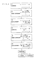
- the multi-color image is formed in accordance with the flow chart of Fig. 4.
- Fig. 4 illustrates the variations in the surface potential of the image retainer.
- reference letters PH denote the exposed portion of the image retainer
- letters DA denote the unexposed portion of the image retainer
- letters T1 denote the toner deposited onto the image retainer by a first development
- letters T2 denote the toner deposited to the image retainer by a second development
- letters DUP denote the rise of the potential, which has been caused by the deposition of toner T1 to the exposed portion PH by the first development.
- the polarity of the latent image is assumed to be positive.
- Similar processes are accomplished a desired number of times to form the multi-color image on the image retainer.
- This multi-color toner image is transferred to the transfer material and is fixed by heat or under pressure to attain a multi-color recorded image.
- the toner and charges residing on the surface of the image retainer are cleaned so that they may be used for forming a subsequent multi-color image.
- the above-specified process can be applied not only to the multi-color image but also to an apparatus for forming a recorded image by composing toner images on an image retainer and transferring them as a whole.
- colors are generated (e.g., additive mixture of colors) in a dummy manner on the recording paper by not superposing but distributing on principle the multi-color toners T1 and T2 on the image retainer 1, as shown in Fig. 5A.
- colors are generated (e.g., subtractive mixture of colors) by developing toners of different colors in a superposed manner on a toner image of a certain color, as shown in Fig. 5B.
- the color reproductivity of the methods (1) and (2) usually become different even if a common toner is used.
- a method having the methods (1) and (2) in a compatible manner is frequently adopted because the color reproducing range can be widened to reproduce many colors.
- the black toner using carbon black according to the prior art has such a wide absorption wavelength range as to substantially absorb not only a visible light but also most lights to which the photoconductive layer of the image retainer is sensitive. If the development with the black toner is accomplished prior to those with the yellow, magenta and cyan toners in case a multi-color image is to be formed with the other toners, the toners of the other colors are not developed in the positions where the Black toner is applied, as has been described hereinbefore. As a result, anything but a color having low lightness and saturation can be reproduced.
- the above phenomenon depends on the fact that the toner T receives a strong electrostatic force in a direction parallel to the surface of the image retainer as shown in Fig. 12. Arrows show lines of electrostatic force and the positively charged toner T attached on the photoconductive layer 12 receives forces in the direction of the electrostatic force.
- toner is attached on the image retainer in the form of multi-layers.
- the apparatus is soiled and the recording paper is stained by moving the toner on the image retainer to the another position by a little cause, such as electrical, optical or mechanical external forces.
- a portion where the toner on the image retainer is attached is subjected to each step of charging ⁇ image exposing ⁇ developing ⁇ charging ⁇ Vietnamese, and a portion where the toner is not attached is subjected to the charging step repeatedly. Accordingly, the electric potential at the charging start time in the charging steps after the first charging step is varied due to the fact whether the toner is attached or not, or what color toner is attached. Accordingly, the surface potential of the image retainer becomes uneven, so that the toner or carrier is attached on the non-image portion or image portion on the image retainer, thereby causing the image noise or color turbidity.
- the surface potential is varied according to the hysteresis of the position.
- Such a method of uniformly exposing before charging may be considered to avoid the variation, such exposure light is absorbed by the toner on the image retainer, so that a sufficient effect can not be expected and the image becomes vague due to the state as shown in Fig. 12.
- the method of bringing a cleaning blade or a fur brush into contact with the image retainer to mechanically scrape off the toner left after the transfer is the most effective and is generally used.
- an object of the present invention to provide an image forming method capable of clearly recording a black color at all times and expressing the colors in a balanced manner.
- an image forming method which is carried out by subjecting an image retainer having a photoconductive layer to an image exposure to form a latent image, by developing this latent image with a first toner having such optical transmissivities as to substantially absorb all the light in the visible range but transmit a light in a wavelength range of 750 nm or more, by subjecting said image retainer to an image exposure with a light having such a wavelength component as to be transmitted through said toner to form a latent image, and by developing this latent image with a second toner.
- the toners are developed in a superposed manner on the same position of the image retainer, it is unavoidable that the contrast of the latent image potentials is gradually reduced by the charges of the toner previously developed. As a result, especially if three colors are superposed, the amount of deposition of the toner of the third color will become short.
- the black color should be able to be reproduced with the yellow, magenta and cyan toners. However, this black reproduction is made remarkably difficult by the aforementioned imbalance of the latent images.
- the black toner in addition to the yellow, magenta and cyan toners.
- the black color is prepared not by a single coloring agent of the carbon black but by composing a plurality of coloring agents of yellow, magenta and cyan etc.
- These coloring agents are so selected to have transmissive components in the invisible range so that the composed color agent of the black color obtained may transmit a light of the invisible range. Moreover, the visible light is absorbed substantially completely.
- These coloring agents thus obtained are used to prepare the toner, i.e., the black toner. Coloring agents other than of yellow, magenta and cyan may be used.
- the black toner can be developed prior to the other toners.
- the light source used for the image exposure has a spectral distribution in the wavelength range transmitting the black toner but not the invisible rays.
- a latent image can be formed on the black toner so that the toner of another color can be developed on the black toner image.
- the black toner is formed in the upper portion on the transfer material so that the portions of the black color can be developed clearly whereas the portions of the chromatic colors can be developed in a well balanced manner.
- the Black toner using a coloring agent other than the carbon black is disclosed in Japanese Patent Laid-Open Nos. 48 - 63727, 57 - 119363, 58 - 150967 and 60 - 239769.
- the use of the black toner is proposed to transfer the single-color toner image, to clean the image retainer or detect the toner density.
- second and later image exposure lights have to be transmitted through the black toner previously developed. So far as this condition is satisfied, it is possible to use the black toner disclosed in the above-specified Patent Laid-Open.
- a multi-color image is to be formed with toners of yellow, magenta, cyan and black, for example, the image exposure light is required for the same reason to be transmitted through not only the black toner but also the yellow, magenta and cyan toners except the last developed one.
- what has a transmissive wavelength range commonly to all the toners is in reality a near infrared light having a wavelength of 750 nm or more.
- the combination of the image exposure light having an infrared component and the toner transmitting the infrared component satisfies the condition of the present invention.
- an image forming method comprising the steps of: forming a latent image by subjecting an image retainer having a photoconductive layer to an image exposure; forming a toner image by developing said latent image with a toner; repeating at least one time each the step of forming said latent image and the step of forming said toner image; transferring a plurality of toner images formed on said image retainer to a transfer material; and uniformly exposing said image retainer on which toner exists with a light containing a wavelength component of 750 nm or more, wherein at least one of said toner images is formed with a toner which has such a spectral transmissivity as to substantially absorb a visible light but substantially transmit a light having a wavelength of 750 nm or more.
- the uniformly exposing step means an exposure before transfer, an exposure before charging or an exposure before cleaning.
- the problems of the exposure under the existence of the toner according to the prior art are caused by the difference in the spectral transmissivities of the individual toners.
- their effective amount reaching the image retainer depends upon the value which is obtained by integrating the product of the intensity of the light irradiated by exposure means, the transmissivities of the toners and the optical sensitivity of the image retainer with respect to the wavelength. This integrated value is small for a specific uniform exposure to raise the aforementioned problems.
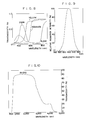
- Fig. 8 illustrates the spectral transmissivities of the yellow, magenta and cyan toners.
- the spectral characteristics of this toner are measured by applying an excellently transmissive both-side tape to one side of an OHP sheet to prepare an adhesive face.
- the toner is uniformly applied to this adhesive face to form a substantially single toner layer, which is melted by the solovent, smoothed in the thickness of 5 - 10 ⁇ m, and dried to measure the spectral transmissivity. This is corrected with the spectral transmissivity of the OHP only into the spectral transmissivity of the toner.
- the spectrophotometer HITACHI 330 type of Hitachi, Ltd., and the wavelength is within a range of 360 to 850 nm.
- a white light for example, is used as a exposure light before cleaning
- the effective exposure amount is dependent upon the toner existing on the image retainer, as will be found in view of Fig. 8.
- the prior art toner using the carbon black as its coloring agent has such a wide absorption wavelength range as to substantially absorb not only the visible light but also the light of the wavelength range to which the photoconductive layer of the image retainer is sensitive.
- the spectral transmissivity of this black toner is plotted by a broken curve in Fig. 8.
- a uniform exposure is accomplished after a toner image has been formed with the black toners, its light is absorbed by the black toner to raise the aforementioned problems. Therefore, the uniform exposure light is not sufficient, if it is transmitted through the yellow, magenta and cyan toners, but has to be transmitted through the black toner, too.
- the spectral transmissivity of the black toner has to be identical to those of the other toners.
- the black toner using coloring agents other than the carbon black is disclosed in Japanese Patent Laid-Open Nos. 48 - 63727, 57 - 119363, 58 - 150967 and 60 - 239769.
- the black toners disclosed in the above-specified Patent Laid-Open can be used so long as it satisfies the conditions that the transmissive wavelength range of the black toner is shared with those of the other color toners and that the exposure light has that wavelength component.
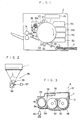
- Fig. 1 shows a multi-color image forming apparatus constructed according to one embodiment of the present invention.
- reference numeral 1 denotes an image retainer rotating in the direction of arrow;
- numeral 21 a corona charging device;
- letter L an image exposure light emitted from a laser optical system 26;
- numerals 5A, 5B, 5C and 5D developing devices having the yellow, magenta, cyan and black toners;
- numeral 33 a transfer electrode;
- numeral 34 a separation electrode; letter P sheets of recording paper;
- numeral 36 a cleaning device having a fur brush 36a, a toner recovery roller 36b and a scraper 36c.
- the multi-color image forming apparatus thus constructed forms a multi-color image in the following manner.
- the image retainer 1 is uniformly irradiated, if necessary, by an exposure lamp 20 and is then uniformly charged by the corona charging device 21 consisting of a scorotron charging electrode. Subsequently, the image retainer 1 is irradiated with the image exposure light L emitted from the laser optical system 26 in accordance with recording data. Thus, an electrostatic latent image is formed.
- This latent image is developed by the developing device 5D containing a first toner T1 (i.e., the black toner).
- the image retainer provided with the toner image is uniformly charged again by the corona charging device 21 and is exposed to an image exposure light L according to the recording data of another color component.
- the electrostatic latent image thus formed is developed by the developing device 5C containing a second toner T2 (i.e., the cyan toner).
- the image retainer 1 is provided thereon with a two-color toner image with the first toner T1 and the second toner T2.
- a toner T3 i.e., the magenta toner
- a toner T4 i.e., the yellow toner
- This multi-color toner image thus obtained on the image retainer 1 is uniformly irradiated, if necessary, by an exposure lamp 30 before transfer and is then transferred to the recording paper P by the transfer electrode 33. Then, this recording paper P is separated from the image retainer 1 by the separation electrode 34 and is fixed by a fixing device 31. In this meanwhile, the image retainer 1 is uniformly exposed by an exposure lamp 35 before cleaning and is then cleaned by the cleaning device 36. The fur brush 36a of the cleaning device 36 is held out of contact with the image retainer 1 during the image formation. If the multi-color image is formed on the image retainer 1, the fur brush 36a is brought into contact with the image retainer 1, after the multi-color image has been transferred, so that it scrapes off the toners left after the transfer while rotating in the direction of arrow.
- the fur brush 36a leaves again the image retainer 1.
- the toner recovery roller 36b is suitably biased, while rotating in the direction of arrow, to recover the toner T or the like from the fur brush 36a.
- the toner T thus recovered is further scraped off by the scraper 36c.
- Fig. 2 The laser optical system 26 of the embodiment is shown in Fig. 2.
- reference numeral 37 denotes a semiconductor laser diode
- numeral 38 a polygon mirror
- numeral 39 an f ⁇ lens.
- Fig. 3 is a section showing the developing device 5A.
- reference numeral 51 denotes a housing; numeral 53 a sleeve; numeral 54 magnetic field generation means or a magnetic roll disposed in a developer carrying member, i.e., sleeve and having N and S poles; numeral 55 a layering member; numeral 56 a fixing member for fixing the layering member 55; numeral 57 a first agitation member; and numeral 58 a second agitation member.
- Numeral 59 denotes a sleeve cleaning member; numeral 60 a developing bias power source; numeral 18 a development region, i.e., the region in which the toner carried by the sleeve 53 is moved upon receiving the electrostatic force from the image retainer; letter T the toner; and letter D a developer.
- the two agitation members 57 and 58 are in the form of a screw which is rotated in the directions of arrows to agitate and carry the developer.
- the agitation member 57 is shaped to carry the developer toward the reader with respect to the drawing sheet whereas the agitation member 58 is shaped to carry the developer apart from the reader.
- a wall 52 by which the developers at the right and left sides of the drawing sheet are exchanged at that region.
- the toner supply to this developing device 5 is accomplished from this side of Fig. 3 so that the toner supplied is generally circulated into the paper surface by the agitation member 58 and out of the paper surface by the agitation member 57 until it is uniformly mixed with the carrier.
- the position of the toner supply should not be limited to the above arrangement but may be modified such that the toner is uniformly supplied to the sleeve shaft from the righthand side of Fig. 3, for example.
- the developer D is sufficiently agitated and mixed and is carried in the same direction as the rotating direction of the sleeve 53 by the carrying force of the sleeve 53 and the magnetic roll 54 rotating in the directions of the arrows.
- the layering member 55 held by the fixing member 56 extending from the housing 52 is forced into contact with the surface of the aforementioned sleeve 53 so that it regulates the amount of the developer D carried to form a developer layer.
- the developer layer when the development of the present embodiment is to be accomplished, there can be used either of the known means such as a magnetic or non-magnetic regulating plate, which is arranged at a constant spacing from the sleeve, or a magnetic roll which is arranged in the vicinity of the sleeve.
- a magnetic or non-magnetic regulating plate which is arranged at a constant spacing from the sleeve, or a magnetic roll which is arranged in the vicinity of the sleeve.
- the smaller diameter of the carrier and toner composing the developer is the more advantageous for the resolution of the image quality and the reproductivity of gradation.
- the carrier of the developer layer has a small diameter of 40 microns or less, the impurity or granule in the developer can be eliminated automatically to form a magnetic brush having a uniform length by means of the aforementioned layering member 55 or the like.
- the aforementioned carrier is made to have a diameter as small as that of the toner, too, the impurity can be prevented from any inclusion to form a magnetic brush having a uniform length.
- the sleeve cleaning roller 59 rotates in the direction of the arrow (as shown in Fig. 3) to scrape off the developer, which has passed through a developing region 18 and consumed the toner T, from the sleeve 53. This makes it possible to maintain the amount of the toner T to be carried to the developing region so that the developing condition is stabilized.
- composition of the developer to be used in the developing method of the present embodiment will be described in the following.
- Toner composition polystyrene 45 wt. parts polymethyl methacrylate 44 wt. parts burrfast (charge controller) 0.2 wt. parts coloring agent 10.5 wt. parts
- This composition is mixed, blended and classified to prepare a desired toner.
- This composition is mixed, blended and classified until it is treated with hot air into a spheric carrier.
- the known one is used as the coloring agent of the chromatic toners (e.g., yellow, magenta and cyan), as will be exemplified in the following: Benzidine Yellow G (C.I. 21090); Benzidine Yellow GR (C.I. 21100); Permanent Yellow DHG (produced by Hoechst); Brilliant Carmine 6B (C.I. 15850); Rhodamine 6G Lake (C.I. 45160); Rhodamine B Lake (C.I. 45170); Rhthalocyanine Blue non Crystal (C.I. 74160); Phthalocyanine Green (C.I.
- the coloring agent of the black toner used is prepared by mixing a plurality of kinds of coloring agents.
- the conditions for these coloring agents to be mixed are as follows:
- the black color can be expressed.
- the light in the common wavelength range can be transmitted through the black toner. Therefore, if this light is used for the image exposure, as has been described hereinbefore, an excellent latent image can be formed.
- the wavelength measured was within a range of 360 to 850 nm.
- this toner is used in the apparatus of Fig. 1 under the condition as tabulated in Table 1, a latent image of high contrast is obtained no matter what order the color is, in case the light absorption rate is 0.4 or preferably 0.2 or less in the main wavelength of the image exposure.
- this black toner is previously developed, a toner of another color can be superposed thereon in the case of the reversal development so that a multi-color image in excellent color balance can be attained with the black color being suitably stressed on the transfer material.
- the semiconductor laser used for the image exposure is well known in the prior art and has a main wavelength of 780 nm.
- the light having this wavelength will be transmitted through not only the above-specified black toner but also the individual yellow, magenta and cyan toners.
- the exposure lamp 20,30, 35 may be exemplified by a variety of light source for emitting infrared rays or a white light source covered with an infrared transmissive filter.
- the spectral transmissivity of this combination is plotted in Fig. 10.
- the exposure lamp 20,30,35 used belongs to the above item (1) or (2).
- Fig. 13 is a graph plotting the spectral sensitivity of the image retainer.
- a toner and an image forming method which can clearly record a black color at all times and express colors in a well-balanced fashion.
- a multi-color image forming method which can sufficiently clean the residual toner from the image retainer by the cleaning device while preventing the toner dispersion and solving the problem of blotting the inside of the apparatus and the recording paper.
- the surface potential of the image retainer can be made constant irrespective of the hysteresis of each position to stably form a multi-color image having neither noise nor color turbidity.
- a multi-color image forming method which can effect an excellent transfer to a sheet recording paper while solving the problem that the toner on the image retainer sill shift to another position to deteriorate the image quality and blot the recording paper.
Landscapes
- Physics & Mathematics (AREA)
- General Physics & Mathematics (AREA)
- Color Electrophotography (AREA)
Applications Claiming Priority (10)
| Application Number | Priority Date | Filing Date | Title |
|---|---|---|---|
| JP294292/86 | 1986-12-09 | ||
| JP61294293A JPS63146055A (ja) | 1986-12-09 | 1986-12-09 | 多色像形成方法 |
| JP294291/86 | 1986-12-09 | ||
| JP61294291A JP2684035B2 (ja) | 1986-12-09 | 1986-12-09 | 多色画像形成方法 |
| JP61294292A JPS63144367A (ja) | 1986-12-09 | 1986-12-09 | 像形成方法 |
| JP294293/86 | 1986-12-09 | ||
| JP61296890A JPS63148274A (ja) | 1986-12-12 | 1986-12-12 | 多色像形成方法 |
| JP29688986A JPS63148273A (ja) | 1986-12-12 | 1986-12-12 | 多色像形成方法 |
| JP296890/86 | 1986-12-12 | ||
| JP296889/86 | 1986-12-12 |
Publications (4)
| Publication Number | Publication Date |
|---|---|
| EP0271334A2 true EP0271334A2 (de) | 1988-06-15 |
| EP0271334A3 EP0271334A3 (en) | 1988-10-19 |
| EP0271334B1 EP0271334B1 (de) | 1991-04-03 |
| EP0271334B2 EP0271334B2 (de) | 1995-05-24 |
Family
ID=27530848
Family Applications (1)
| Application Number | Title | Priority Date | Filing Date |
|---|---|---|---|
| EP87310838A Expired - Lifetime EP0271334B2 (de) | 1986-12-09 | 1987-12-09 | Verfahren zur Herstellung eines Bildes |
Country Status (3)
| Country | Link |
|---|---|
| US (1) | US4897330A (de) |
| EP (1) | EP0271334B2 (de) |
| DE (1) | DE3769100D1 (de) |
Cited By (2)
| Publication number | Priority date | Publication date | Assignee | Title |
|---|---|---|---|---|
| EP0467609A3 (de) * | 1990-07-16 | 1992-12-30 | Minnesota Mining And Manufacturing Company | Verfahren und Gerät zum mehrfachen elektrischen Laden einer Photoleiterschicht |
| US5606398A (en) * | 1995-04-28 | 1997-02-25 | Minnesota Mining And Manufacturing Company | Reduction of residual potential and ghosting in a photoconductor |
Families Citing this family (4)
| Publication number | Priority date | Publication date | Assignee | Title |
|---|---|---|---|---|
| US5372906A (en) * | 1989-02-08 | 1994-12-13 | Konica Corporation | Image forming method |
| US5262264A (en) * | 1990-02-27 | 1993-11-16 | Dainippon Ink And Chemical, Inc. | Combination of color toners for developing electrostatic latent image |
| JP2004102273A (ja) * | 2002-08-22 | 2004-04-02 | Canon Inc | 画像形成装置 |
| US7838192B2 (en) * | 2007-04-24 | 2010-11-23 | Xerox Corporation | Methods for making customized black toners |
Family Cites Families (11)
| Publication number | Priority date | Publication date | Assignee | Title |
|---|---|---|---|---|
| US3873310A (en) * | 1971-12-28 | 1975-03-25 | Lloyd F Bean | Method of controlling the brightness acceptance range and tonal contrast of a xerographic plate |
| JPS5721708B2 (de) * | 1972-05-25 | 1982-05-08 | ||
| JPS57104948A (en) * | 1980-12-23 | 1982-06-30 | Olympus Optical Co Ltd | Multi-sheet copying electrophotographic method |
| JPS5811957A (ja) * | 1981-07-16 | 1983-01-22 | Toyo Electric Mfg Co Ltd | 静電記録方式における多色現像方法 |
| US4510223A (en) * | 1983-02-07 | 1985-04-09 | Coulter Systems Corporation | Multicolor electrophotographic imaging process |
| EP0143535B1 (de) * | 1983-10-03 | 1990-12-27 | Konica Corporation | MI-Vielfach-Bild-Reproduktionsverfahren |
| JPS60239769A (ja) * | 1984-05-14 | 1985-11-28 | Canon Inc | 画像形成装置 |
| DE3531098A1 (de) * | 1984-08-30 | 1986-03-13 | Konishiroku Photo Industry Co. Ltd., Tokio/Tokyo | Bilderzeugungsverfahren |
| US4696880A (en) * | 1984-09-06 | 1987-09-29 | Konishiroku Photo Industry Co., Ltd. | Method and apparatus for reproducing multi-color image and photoreceptor thereof |
| US4654282A (en) * | 1986-05-01 | 1987-03-31 | Eastman Kodak Company | Plural electrophotographic toned image method |
| JP2932866B2 (ja) * | 1992-10-21 | 1999-08-09 | 日本電気株式会社 | ディジタル加入者線伝送システム |
-
1987
- 1987-12-09 DE DE8787310838T patent/DE3769100D1/de not_active Expired - Fee Related
- 1987-12-09 EP EP87310838A patent/EP0271334B2/de not_active Expired - Lifetime
- 1987-12-09 US US07/130,686 patent/US4897330A/en not_active Expired - Lifetime
Cited By (2)
| Publication number | Priority date | Publication date | Assignee | Title |
|---|---|---|---|---|
| EP0467609A3 (de) * | 1990-07-16 | 1992-12-30 | Minnesota Mining And Manufacturing Company | Verfahren und Gerät zum mehrfachen elektrischen Laden einer Photoleiterschicht |
| US5606398A (en) * | 1995-04-28 | 1997-02-25 | Minnesota Mining And Manufacturing Company | Reduction of residual potential and ghosting in a photoconductor |
Also Published As
| Publication number | Publication date |
|---|---|
| DE3769100D1 (de) | 1991-05-08 |
| EP0271334B1 (de) | 1991-04-03 |
| EP0271334A3 (en) | 1988-10-19 |
| EP0271334B2 (de) | 1995-05-24 |
| US4897330A (en) | 1990-01-30 |
Similar Documents
| Publication | Publication Date | Title |
|---|---|---|
| US4894685A (en) | Multicolor image forming method and apparatus | |
| US4814797A (en) | Apparatus and method for controlling color dot size in multicolor image | |
| US4839692A (en) | Apparatus for reproducing multi-color image | |
| US4756985A (en) | Method of forming multicolor images | |
| JP2003186246A (ja) | 電子写真用カラートナー並びにそれを用いた電子写真用カラートナーセット、電子写真用カラー現像剤、カラー画像形成方法及びカラー画像形成装置 | |
| EP0271334B2 (de) | Verfahren zur Herstellung eines Bildes | |
| JPH0535038A (ja) | 電子写真装置 | |
| JP2684035B2 (ja) | 多色画像形成方法 | |
| US5338631A (en) | Method of forming color images | |
| JPS61172159A (ja) | 多色画像形成方法 | |
| JPH0263225B2 (de) | ||
| JPH01266554A (ja) | 光導電性トナー及び画像形成装置 | |
| JPS6031150A (ja) | カラ−画像形成方法 | |
| JPS63148273A (ja) | 多色像形成方法 | |
| JPH08328344A (ja) | クリーナレスフルカラー画像形成方法 | |
| JPH02271371A (ja) | 画像形成装置 | |
| JP3298035B2 (ja) | 電子写真現像用トナー及び画像形成方法 | |
| JPS63146055A (ja) | 多色像形成方法 | |
| JPS59223466A (ja) | カラ−画像記録方法 | |
| EP0175243A1 (de) | Verfahren und Vorrichtung zur Reproduktion von Mehrfarbenbildern und Photorezeptor davon | |
| JPS63301962A (ja) | 電子写真用トナ− | |
| JPH0562336B2 (de) | ||
| JPS63301963A (ja) | 電子写真用トナ− | |
| JPS58111953A (ja) | 多色印字方法 | |
| JPS63144367A (ja) | 像形成方法 |
Legal Events
| Date | Code | Title | Description |
|---|---|---|---|
| PUAI | Public reference made under article 153(3) epc to a published international application that has entered the european phase |
Free format text: ORIGINAL CODE: 0009012 |
|
| AK | Designated contracting states |
Kind code of ref document: A2 Designated state(s): DE FR GB IT NL SE |
|
| PUAL | Search report despatched |
Free format text: ORIGINAL CODE: 0009013 |
|
| AK | Designated contracting states |
Kind code of ref document: A3 Designated state(s): DE FR GB IT NL SE |
|
| 17P | Request for examination filed |
Effective date: 19890323 |
|
| 17Q | First examination report despatched |
Effective date: 19890703 |
|
| ITF | It: translation for a ep patent filed | ||
| GRAA | (expected) grant |
Free format text: ORIGINAL CODE: 0009210 |
|
| AK | Designated contracting states |
Kind code of ref document: B1 Designated state(s): DE FR GB IT NL SE |
|
| PG25 | Lapsed in a contracting state [announced via postgrant information from national office to epo] |
Ref country code: SE Effective date: 19910403 Ref country code: NL Effective date: 19910403 |
|
| REF | Corresponds to: |
Ref document number: 3769100 Country of ref document: DE Date of ref document: 19910508 |
|
| EN | Fr: translation not filed | ||
| PG25 | Lapsed in a contracting state [announced via postgrant information from national office to epo] |
Ref country code: FR Effective date: 19910823 |
|
| NLV1 | Nl: lapsed or annulled due to failure to fulfill the requirements of art. 29p and 29m of the patents act | ||
| PLBI | Opposition filed |
Free format text: ORIGINAL CODE: 0009260 |
|
| 26 | Opposition filed |
Opponent name: CANON INC. Effective date: 19920102 |
|
| REG | Reference to a national code |
Ref country code: FR Ref legal event code: ST |
|
| PUAH | Patent maintained in amended form |
Free format text: ORIGINAL CODE: 0009272 |
|
| STAA | Information on the status of an ep patent application or granted ep patent |
Free format text: STATUS: PATENT MAINTAINED AS AMENDED |
|
| 27A | Patent maintained in amended form |
Effective date: 19950524 |
|
| AK | Designated contracting states |
Kind code of ref document: B2 Designated state(s): DE FR GB IT NL SE |
|
| EN3 | Fr: translation not filed ** decision concerning opposition | ||
| PGFP | Annual fee paid to national office [announced via postgrant information from national office to epo] |
Ref country code: GB Payment date: 19981211 Year of fee payment: 12 |
|
| PGFP | Annual fee paid to national office [announced via postgrant information from national office to epo] |
Ref country code: DE Payment date: 19981221 Year of fee payment: 12 |
|
| PG25 | Lapsed in a contracting state [announced via postgrant information from national office to epo] |
Ref country code: GB Free format text: LAPSE BECAUSE OF NON-PAYMENT OF DUE FEES Effective date: 19991209 |
|
| GBPC | Gb: european patent ceased through non-payment of renewal fee |
Effective date: 19991209 |
|
| PG25 | Lapsed in a contracting state [announced via postgrant information from national office to epo] |
Ref country code: DE Free format text: LAPSE BECAUSE OF NON-PAYMENT OF DUE FEES Effective date: 20001003 |
|
| PG25 | Lapsed in a contracting state [announced via postgrant information from national office to epo] |
Ref country code: IT Free format text: LAPSE BECAUSE OF NON-PAYMENT OF DUE FEES;WARNING: LAPSES OF ITALIAN PATENTS WITH EFFECTIVE DATE BEFORE 2007 MAY HAVE OCCURRED AT ANY TIME BEFORE 2007. THE CORRECT EFFECTIVE DATE MAY BE DIFFERENT FROM THE ONE RECORDED. Effective date: 20051209 |